TUCTA22TA26Remote Control
Long-E Technology (Shenzhen) Co., Ltd.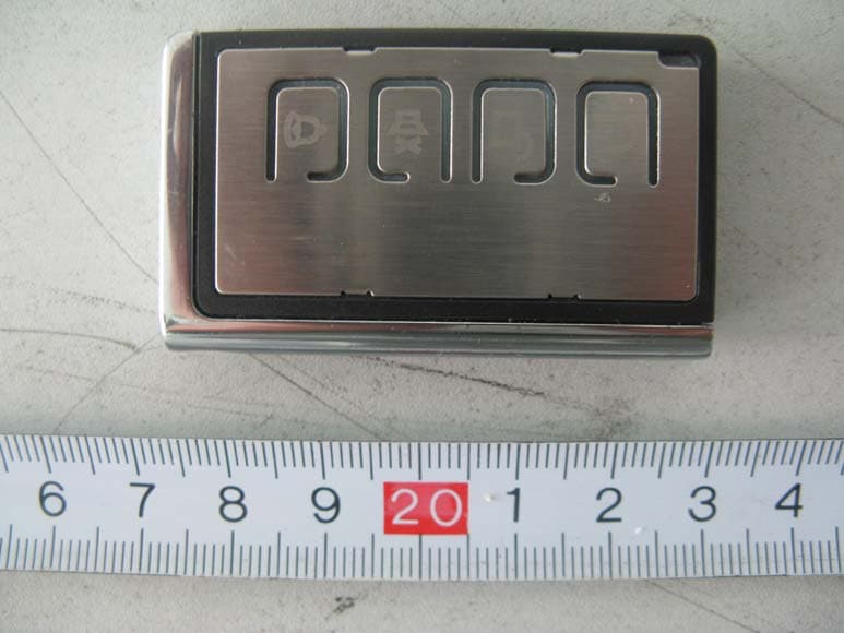
Click to zoom
Application Details
- Equipment Class
- DSC - Part 15 Security/Remote Control Transmitter
- Date of Grant
- Dec 30, 2007
- Application Purpose
- Original Equipment
- Date of Application
- Dec 30, 2007
- Equipment Note
- Remote Control
- Frequency Range
- 315.00000000 - 315.00000000
- Country
- China
Documents & Files
Document Text
Text extracted from the exhibit documents filed with the FCC. Open a document above to read the original.
Users Manual
User Manual GS-500A W/O ANTI HIJACKING FUNCTIONAL MANUAL Button Press function Conditions 0.5 seconds Arm/door lock Lock the door Stop alarm sounding Alarm is disarmed In valet mode Alarm sounding 1 2 seconds panic Anytime 0.5 seconds Disarm/door unlock Unlock doors Stop alarm sounding and disarm Alarm is being armed In valet mode Alarm sounding 2 2 seconds Auxilary 1 output (trunk release ) Anytime 1 Æ 1 Æ Within 5 seconds Arm bypassing shock sensor Alarm is disarmed 1+2 + 2 seconds Auxilary 2 output Anytime 2 Æ 2 Æ Within 5 seconds Passenger unlock Alarm is being armed 3 2 seconds Car finder Anytime 3 Æ 1 Æ Within 10 seconds Silent arming/door lock Alarm is disarmed 3 Æ 2 Æ Within 10 seconds Silent disarming / door unlock Alarm is being armed 4 0.5 seconds Shift for 2 car operation Anytime The system is supplied with two 4-buttons remote transmitters used to control system operations. Button 1 arms the system and when held for 2 seconds, activates the system’s panic feature. Button 1 also locks the doors when the system is in valet mode. Button 2 disarms the system. Pressing button 2 again operates the passenger unlock feature (if installed). Button 2 also unlock s the doors when the system is in valet mode. To hold the button 2 for 2 sec onds shall activate the auxiliary channel output 1 for trunk release function; This output will remain on for as long as the button is pressed. Button 3 activates the silent operation for the arming and disarming. Press button 3 then button 1 arms the system silently. Press button 3 then button 2 disarms the system silently. Press button 3 for 2 seconds activates the vehicle locator featur e which flashes the parking lights and chirps the siren 5 time s. This feature is useful to help locate the vehicle in a crowded parking lot. Button 1+2 activates the auxiliary 2 output. This output will remain on for as long as the button is pressed. Button 4 is the page shift button. The page shift button will change the function of buttons 1 through 4 each time it is presse d, allowing access to additional features or multiple car operation. Each time the sh ift button is pressed, the led on the transmitter will illuminat e and the transmitter functions will shift to the next page, allowing access to another set of features. Once shifted to another page(there are 4 pag es total), the transmitter will remain on that page for 10 seconds or until a butto n is pressed, then return to page 1. each time a transmitte r button is pressed and held, the led will flash a number of times to indicate from which page it is transmitting. Under normally operation, only p ages 1 and 2 are used. Page 3 and 4 are usually used for two car operation. 1. ADDING/REPLACING TRANSMITTERS (Code learning) To replace lost or stolen transmitters or to add additional tr ansmitters into the system, have all desired transmitters ready a nd follow the steps below. NOTE: Up to 4 transmitters can be programmed to operate the system. To erase any previously stored tran smitter codes, be sure to pro gram all 4 transmitter memory location. To program the transmitter(s): 1) Turn on the ignition key on, off, on, off, and back on. The sire will chirp 3 times. 2) Press and hold the override switch for 3 seconds. The siren will chirp 5 times. The led will illuminate. 3) Press any button on the first transmitter. The siren will chirp once. 4) Press any button on the first transmitter again. The siren will chirp twice to indicate it has learned the code. 5) Repeat steps 3 and 4 for each transmitter (up to 4). 6) Turn off the ignition key. ***TWO CAR OPERATION If two vehicles are equipped with this system, for convenience both can be operated using the same remote transmitter. If all f our transmitters are to be used with both cars, program transmitters A and B into the first vehicle in the manner described above. Program transmitt ers C and D by pressing the shift button twice before performing steps 3 and 4 above. When finished programming the first vehicle, program transmitters C and D into the second vehicle as normal, then program trans mitters A and B by pressing the shift button twice before performing steps 3 and 4 above. When programmed in this manner, the driver of the first car can also operate the second vehicle by pressing the shift button tw ice and the desired function button. 2. REMOTE ARMING The system monitors independent areas (zones) while arme d: doors, hood/trunk, shock sensor and optional sensor input. To arm the system: 1) Turn off the ignition. 2) Press button 1. The siren will chirp once. The doors will lock. The parking lights wi ll flash once. The led will turn on red, to indicate the s tarter defeat is activate. 3) 5 second after arming: The led will start blinking to indicate that the doors and ho od/trunk inputs are being monitored. (see function selection #11 f or door input monitoring on the delay time) z During arming, if the system detects a bad sensor or an open zo ne, the system will chirp 4 additional times and ignore that inp ut, but keep all other areas protected. Once armed, the alarm will trigger when any of the following occurs: The doors are opened. The hood or trunk is opened. The shock senor de tects an impact to the vehicle. The optional sensor is dis turbed. When the alarm triggers, the siren will sound, the horn will honk, and the parking lights will flash, the led will flash rapidl y. The system alarm will last for 30 seconds. In the event the alarm is triggered and remains triggered conti nuously by the same sensor or input during a single arming cycle , that sensor or input will be automatically bypassed until the next time the system is armed. If the shock sensor detects a light impact to the vehicle, or th e optional sensor’s warn-away zone is disturbed, the siren will chirp 5 times as a warning indication. If the heavy impact is detected, the siren shall sound continuously with flashing the parking light at the same time. 3. REMOTE DISARMING To disarm the…
Text truncated - open the document above for the full version.
Block Diagram
1234 A B C D 4 321 D C B A BATTERY OSC ENCODER ANT 315MHz Block Diagram of Remote Control 315MHz Key ModulationAmplifier
External Photos
EXHIBIT B - EUT EXTERNAL PHOTOGRAPHS EUT– Front View EUT – Bottom View
ID Label/Location Info
EXHIBIT A - FCC ID LABELING AND LOCATION Suggested FCC ID Labeling Suggested FCC ID Location Label Location FCC ID: TUCTA22TA26
Internal Photos
EXHIBIT C - EUT INTERNAL PHOTOGRAPHS EUT- Uncovered View EUT-Main board Top View EUT-Main board Bottom View
Operational Description
TA26 Circuit Description When any button is pressed, the Coding IC HCS320 wakes up( It will sleep and output nothing when all buttons are released ), and encode the keying and the build-in address to serial data which are output from DO pin. The data are combination of high pulse and 0 level which will make the surface acoustic wave oscillator SAW1 and triode Q1 to oscillating or not. The oscillating signal will be coupled to the micro-strip line on PCB through which the signal is emitted out. So, this is the typical ASK or OOK modulation circuit. The transmitter uses the micro-strip line on PCB act as the antenna. The transmitting power is very low.
Schematics
1234 A B C D 4321 D C B A Q1R25 C4 2P C2 3P C1 12P R3 100 SW1 SW2 SW3 R5 68K SAW 315MHZ + B1 BAT1 R4 4.7K R1 4.7K LED A1TA26h320 315MHZ C3 470P SW4 L1 100R D0 1 D1 2 D2 3 D3 4 VSS 5 PWR 6 LED 7 VCC 8 U1 HCS320 C6 103 315MHZ ANT.
Test Report
Note: This test report is for the customer shown above and their specific product only. It may not be duplicated or used in part without prior written consent from Bay Area Compliance Laboratories Corp. (Shenzhen). This report must not be used by the customer to claim product certification, approval, or endorsement by NVLAP, NIST or any agency of the Federal Government. FCC PART 15.231 MEASUREMENT AND TEST REPORT For Agilon Technology (Shenzhen) Co., Ltd. C-6F, HuaHan Chuangxin Block, KeYuan Road, Hi-Tech Industry Zone, Shenzhen, China FCC ID: TUCTA22TA26 This Report Concerns: Original Report Equipment Type: Remote Control Test Engineer: Bruce Zhang Report No.: RSZ07121403 Test Date: 2007-12-20 to 2007-12-27 Report Date: 2007-12-28 Reviewed By: EMC Manager: Green Xu Prepared By: Bay Area Compliance Laboratories Corp. (Shenzhen) 6/F, the 3rd Phase of WanLi Industrial Building, ShiHua Road, FuTian Free Trade Zone Shenzhen, Guangdong, China Tel: +86-755-33320018 Fax: +86-755-33320008 Agilon Technology (Shenzhen) Co., Ltd. FCC ID: TUCTA22TA26 Report # 884897.DOC Page 2 of 20 FCC Part 15.231 Test Report TABLE OF CONTENTS GENERAL INFORMATION.......................................................................................................................................3 PRODUCT DESCRIPTION FOR EQUIPMENT UNDER TEST (EUT) ....................................................................................3 OBJECTIVE...................................................................................................................................................................3 RELATED SUBMITTAL(S)/GRANT(S).............................................................................................................................3 TEST METHODOLOGY..................................................................................................................................................3 TEST FACILITY.............................................................................................................................................................4 SYSTEM TEST CONFIGURATION ..........................................................................................................................5 JUSTIFICATION.............................................................................................................................................................5 EUT EXERCISE SOFTWARE..........................................................................................................................................5 SPECIAL ACCESSORIES.................................................................................................................................................5 EQUIPMENT MODIFICATIONS.......................................................................................................................................5 CONFIGURATION OF TEST SETUP.................................................................................................................................6 BLOCK DIAGRAM OF TEST SETUP................................................................................................................................6 SUMMARY OF TEST RESULTS ...............................................................................................................................7 §15.203 - ANTENNA REQUIREMENT......................................................................................................................8 STANDARD APPLICABLE..............................................................................................................................................8 §15.205, §15.209, §15.231 (B) - RADIATED EMISSIONS ........................................................................................9 MEASUREMENT UNCERTAINTY....................................................................................................................................9 EUT SETUP..................................................................................................................................................................9 EMI TEST RECEIVER SETUP.........................................................................................................................................9 TEST EQUIPMENT LIST AND DETAILS.........................................................................................................................10 TEST PROCEDURE......................................................................................................................................................10 STANDARD APPLICABLE............................................................................................................................................10 CORRECTED AMPLITUDE & MARGIN CALCULATION.................................................................................................10 TEST DATA................................................................................................................................................................11 §15.231(C) - 20DB BANDWIDTH TESTING...........................................................................................................12 REQUIREMENT...........................................................................................................................................................12 TEST EQUIPMENT LIST AND DETAILS.........................................................................................................................12 TEST PROCEDURE......................................................................................................................................................12 TEST DATA................................................................................................................................................................12 §15.231(A) - DEACTIVATION TESTING ...............................................…
Text truncated - open the document above for the full version.
Test Setup Photos
EXHIBIT D - TEST SETUP PHOTOGRAPHS Radiated Emission - Front View Radiated Emission - Rear View
Contact Information
Applicant
Zhongjun Yin(Chief Engineer)
Test Firm
Bay Area Compliance Laboratory Corp. (Shenzhen)John Chan
Technical Specifications
| # | Rule Parts | Frequency Range | Power Output |
|---|---|---|---|
| 1 | 15.231 | 315 MHz - 315 MHz | - |
Other Applications from Long-E Technology (Shenzhen) Co., Ltd.
TUCTA25TA28
Apr 09, 2008Remote Control
Equipment Class
DSC - Part 15 Security/Remote Control Transmitter
TUCTA27TA30
Apr 09, 2008Remote Control
Equipment Class
DSC - Part 15 Security/Remote Control Transmitter
TUCTA31TA37
Apr 09, 2008Remote Control
Equipment Class
DSC - Part 15 Security/Remote Control Transmitter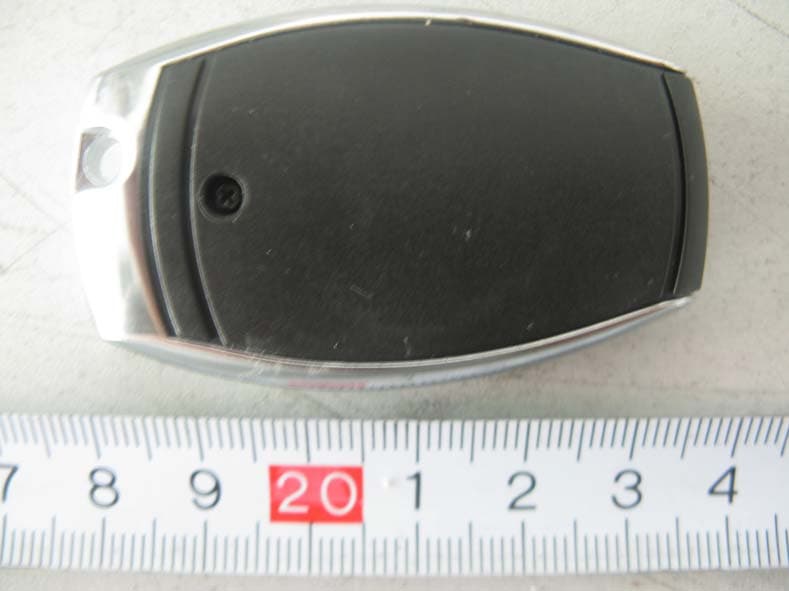
TUCTA24TA29
Dec 30, 2007Remote Control
Equipment Class
DSC - Part 15 Security/Remote Control Transmitter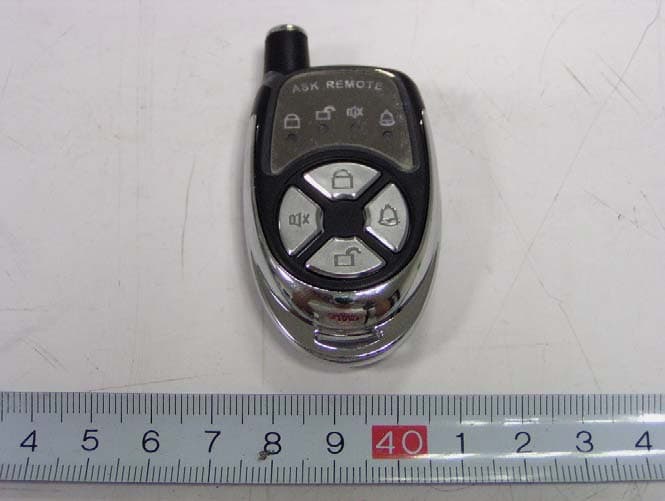
TUCTA16TA19
Nov 19, 2006Remote Control
Equipment Class
DSC - Part 15 Security/Remote Control Transmitter