TUR000910Laser Alignment System
Research Technologies, Inc.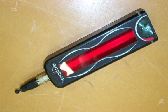
Click to zoom
Application Details
- Equipment Class
- DXT - Part 15 Low Power Transceiver, Rx Verified
- Date of Grant
- Jan 15, 2006
- Application Purpose
- Original Equipment
- Date of Application
- Jan 12, 2006
- Equipment Note
- Laser Alignment System
- Frequency Range
- 915.18000000 - 915.18000000
- Company
- Research Technologies, Inc.
- Country
- United States
Documents & Files
Document Text
Text extracted from the exhibit documents filed with the FCC. Open a document above to read the original.
Users Manual
Laser Measurement System Product Manual v 1.1 12/10/2005 Eclipse Laser Measurement System 2006 Research Technologies 2 Introduction Welcome to the Eclipse Laser Measurement System, the state of the art in automotive frame measurement. The end result of the measurement defines the XYZ position of points in space, each associated with a “target”. This measured data is compared to an as built data base and the differences displayed. This manual is intended not only to introduce you to the system, and to educate you about its individual components, but also to serve as a reference guide to help you through the process of operating the Eclipse system easily, efficiently and profitably. The manual covers three major sections: • An introduction to the hardware of the system including detailed information about each of the system components. • An introduction to the software of this system, including explanations of the operation of each of the screens, as well as walk-throughs of typical software functions. • A thorough troubleshooting section to assist you if you run into questions, and a list of support contacts to help if the troubleshooting doesn’t have what you’re looking for. While we hope this serves as a functional guide on the operation of the Eclipse System, it is not intended to replace the in-depth training an auto body frame alignment technician needs to properly understand and apply the information that this system is capable of providing. If you have questions about the frame repair process, please don’t hesitate to give us a call, and we will refer you to the appropriate local training facility. Eclipse Laser Measurement System 2006 Research Technologies 3 General Warnings The Eclipse Laser Measurement system has been designed to withstand the rigors of the auto body shop environment, but as with any highly sophisticated piece of equipment, a few warnings are appropriate. Eye Safety Complies with Title 21 of the C.F.R as applicable. The two lasers used within the Eclipse Laser Measurement system operate below the eye-safe range of 3.5mW. If the laser beam does strike the eye it can be uncomfortable, so please take measures to not stare directly into the beam. FCC Regulations This device complies with Part 15 of the FCC Rules. Operation is subject to the following conditions: (1) this device may not cause harmful interference (2) this device must accept any interference received, including interference that may cause undesired operations. Changes or modifications not expressly approved by Research Technologies Inc. void the user's authority to operate the equipment. Physical Care The Eclipse Laser scanner is a precision optical instrument, do not drop or subject the head to impacts, as it could misalign the calibrated lasers, and reduce the accuracy of, or disable, measurement functions. The Eclipse Laser Scanner is painted with a highly durable powder coat finish. It is designed to withstand typical abrasion, chemicals, oils, and water. It is not impervious to damage however, so please treat it with care. The finish can be cleaned with any Eclipse Laser Measurement System 2006 Research Technologies 4 normal household cleaner, sprayed onto a cleaning rag, and gently wiped clean. Please avoid bleaches, abrasives, or spraying a large amount of fluid directly onto the scanner. Eclipse Laser Measurement System 2006 Research Technologies 5 Preparation for System use Plug-in the cabinet and turn on the system power switch on the lower rear of the cabinet. Check the Targets are charging in the first draw. The Blue indicator lights on the sides of the target will be lit when they on rapid charge. A continuous trickle is ongoing even when the Target lights on not on. System Setup and Operation Please setup your Eclipse Measurement system according to these steps. 1. Turn on Computer Workstation The Eclipse Computer Workstation must be on for the measurement system to function. Power switches are the front of the computer in the bottom compartment of the System Cabinet. Upon turn on, the keyboard should light up, and normal boot diagnostics should appear on the LCD screen. 2. Place and turn on Laser Scanner Remove the Eclipse Laser Scanner from the slide in the bottom compartment of the System Cabinet. Connect the power supply to 110 AC, and place the scanner underneath the car being measured. The laser should be on near the same horizontal plane as the car frame, and for best performance, located near the center of the automobile. Turn on the Laser Scanner, to create the reference plane of light to which you should setup the targets. 3. Start Eclipse 3D software is running To start the program, please double-click on the Eclipse 3D icon on the desktop. The software suite controls the communications interface between the targets and the computer. The measurement system will not function without the computer running the Eclipse 3D suite. 4. Select automobile model For the software to be able to supply the user with spec points, the specific automobile model, make, and year must be selected. 5. Locate a spec point to attachment to If you use the right button on the mouse to click on a spec point, a dialogue with information about that point will appear, including a picture (if available) of what exact point you should use for mounting the target. This dialogue will also show a suggestion of stem length, given an undamaged point. 6. Secure a Universal Attachment to the attachment point Following the location of the spec point you selected, attach a Universal Attachment to the bolt or chassis penetration that the spec point calls out. The term “attachment” is used to describe a mechanical coupler between the target stem, and the reference points on an auto body frame. Eclipse Laser Measurement System 2006 Research Technologies 6 7. Attach Stem to a Target Select the appropriate length stem to hang from the attachment that will place the plane of the laser beams onto the red active area on the …
Text truncated - open the document above for the full version.
Block Diagram
NCEE Labs Page 24 of 26 Figure 12 - RF Block Diagram
External Photos
NCEE Labs R111105-01-02 Page 18 of 21 Figure 6 - Eclipse Laser Target, Front Figure 7 - Eclipse Laser Target, Back
ID Label/Location Info
Model 2402 This device complies with Part 15 of the FCC Rules. Operation is subject to the following two conditions: (1) this device may not cause harmful interference, and (2) this device must accept any interference recieved, including interference that may cause undesired operations. TM
Test Report
EMC Test Report Company: Research Technologies Inc. 115 Second Ave N, Suite 300 Edmonds, WA 98020 Contact: Claire Rasmussen Product: Eclipse Laser Target FCC ID Number: TUR000910 Test Report No: 111105-01-02A APPROVED BY: Doug Kramer _________________________ Senior Test Engineer DATE: 9 January 2005 Total Pages: 26 The Nebraska Center for Excellence in Electronics (NCEE) authorizes the above named company to reproduce this report provided it is reproduced in its entirety for use by the company’s employees only. Any use that a third party makes of this report, or any reliance on or decisions made based on it, are the responsibility of such third parties. NCEE accepts no responsibility for damages, if any, suffered by any third party as a result of decisions made or actions based on this report. This report applies only to the items tested. NCEE is a FCC registered lab. Registration #100875 R111105-01-02A FCC ID: TUR000910 Page 2 of 26 1.0 Summary of test results 1.1 Test Results 1.2 Test Methods 1.2.1 Conducted Emissions 1.2.2 Radiated Emissions 2.0 Description 2.1 Equipment under test 2.1.1 Identification 2.1.2 EUT received date 2.1.3 EUT tested dates 2.1.4 Manufacturer 2.1.5 Serial number 2.2 Laboratory description 2.3 Special equipment or setup 3.0 Test equipment used 4.0 Detailed Results 4.1 FCC Part 15.203 Unique Connector for Antenna 4.2 FCC Part 15.207 Conducted Emissions 4.3 FCC Part 15.209 Radiated Emissions 4.4 FCC Part 15.249 Operation within the 902-928 MHz Band Appendix A – Test setup photos Appendix B – Emissions plots Appendix C – Bandwidth Data Appendix D – Sample calculation Appendix E – EUT photos Appendix F – RF Block Diagram Appendix G – Table of Figures NCEE Labs R111105-01-02A FCC ID: TUR000910 Page 3 of 26 1.0 Summary of test results 1.1 Test Results Based on the data collected with the unit as configured. 1.2 Test Methods 1.2.1 Conducted Emissions The EUT was powered by an internal rechargeable battery. There was no connection to the AC mains supply network, nor is it an option, therefore conducted emissions measurements are not applicable to this product. 1.2.2 Radiated Emissions Compliance to 47 CFR Part 15 was tested in accordance with the methods of ANSI/IEEE C63.4, 2003. Several configurations were examined and the results presented represent a worst-case scenario. The EUT was placed on a wooden table approximately 80cm high and centered on a 4m diameter turntable. The table was rotated to find the angles of maximum emissions and the antenna was moved from 1m to 4m in both vertical and horizontal positions. All measurements were taken at a distance of 3m. Test Test SpecificationResults 47 CFR, Part 15.203Part 15.203Complies 47 CFR, FCC Part 15.207 Part 15.207, Class BN/A 47 CFR, FCC Part 15.109/209 Part 15.109, Class BComplies 47 CFR, FCC Part 15.249Part 15.249Complies NCEE Labs R111105-01-02A FCC ID: TUR000910 Page 4 of 26 2.0 Description 2.1 Equipment under test The Equipment under test (EUT) was a Research Technologies Eclipse Laser Target for use with a laser alignment system. The target detects the presence of laser light and an infrared sync pulse from the Eclipse Laser Scanner and transmits position data to a PC. The firmware was set to 915MHz transmittion frequency with a BAUD rate of 115,200. 2.1.1 Identification: Eclipse Laser Target 2.1.2 EUT received date: 14 Nov. 2005 2.1.3 EUT tested dates: Nov 22, Dec 1, 2 of 2005 2.1.4 Manufacturer: Research Technologies 2.1.5 Serial number: #63 2.2 Laboratory description All testing was performed at the NCEE Lincoln facility, which is a FCC registered lab. This site has been fully described in a report submitted to your office, and accepted in a letter dated May 4, 2001. Laboratory environmental conditions varied slightly throughout the tests: Relative humidity of 46 ± 4% Temperature of 20 ± 3° Celsius 2.3 Special equipment or setup The EUT’s battery was fully charged prior to testing. The EUT was set to continuously transmit position data. To keep the EUT transmitting, it was required to have the Eclipse laser scanner on the table, so that the target was in the path of the laser. Without the laser presence, the transmitter would not operate. 3.0 Test equipment used Serial # Manufacturer Model Description Last cal. 1647 EMCO 3142B Biconilog antenna 10-Mar-05 6416 EMCO 3115 DRG Horn 12-Oct-05 100037 Rohde & Schwarz ESIB26 EMI Test Receiver 10-Aug-05 082001/003 Rohde & Schwarz TS-PR18 Preamplifier N/A 2575 Rohde & Schwarz ES-K1 Software v1.60 N/A NCEE Labs R111105-01-02A FCC ID: TUR000910 Page 5 of 26 4.0 Detailed Results Radiated emissions measurements were made by first using a spectrum analyzer getting a rough signal spectrum, any points were then measured using a CISPR 16 compliant receiver with the following bandwidth setting: 30MHz - 1GHz: 120kHz IF bandwidth, 60kHz steps 1GHz - 10GHz: 1MHz IF bandwidth, 500kHz steps 4.1 FCC Part 15.203 unique connector for antenna The antenna is inside of the EUT and is permanently attached to the EUT. This is considered sufficient to comply with FCC Part 15.203. 4.2 FCC Part 15.207 Conducted Emissions Conducted emissions measurements were not applicable to this product, as it has no provisions for connecting to the mains network. 4.3 FCC Part 15.209 Radiated Emissions The EUT was found to comply with the published limits. The EUT was tested at 3m and the limits were scaled to reflect those for Class 'B' products at 3m. The limits applied were the same as those for FCC Class 'B' products. See figures 3 and 4 for a plot of the data, Table 1 for tabular data and see figures 1 and 2 for EUT setup. As shown in figures 3 and 4, the EUT complies with the limits. Figure 3 shows a plot from the EUT not transmitting, but ready to receive commands, and table 1 contains tabular data from this mode of operation. 4.4 FCC Part 15.249 Operation within the 902-928 MHz Band The EUT was tested while transmitting at 915MHz. This is the only possible frequency of operation as set in the EUT…
Text truncated - open the document above for the full version.
Test Setup Photos
NCEE Labs R111105-01-02 Page 7 of 21 Figure 1 - Radiated Emissions Test Setup Figure 2 - Radiated Emissions Test Setup
Contact Information
Applicant
Claire Donald Rasmussen(Production Manager)
Technical Contact
Research TechnologiesDarryl Koop
[email protected]425-670-2167
115- 2nd Ave North Suite 300 · Edmonds, Washington · United States
Test Firm
Nebraska Center for Excellence in ElectronicsNic Johnson
Technical Specifications
| # | Rule Parts | Frequency Range | Power Output |
|---|---|---|---|
| 1 | 15C | 915.18 MHz - 915.18 MHz | - |
Other Applications from Research Technologies, Inc.
TUR000220
Jan 15, 2006Laser Alignment System
Equipment Class
DXT - Part 15 Low Power Transceiver, Rx Verified