FCCID.CO- FCC ID Database
HomeCompaniesEquipment ClassesSearch

© 2026 FCC ID Database. All rights reserved.

AboutContactData sourced from FCC public records
  1. Home/
  2. BIOMEC Inc./
  3. TUYCTIG250LC

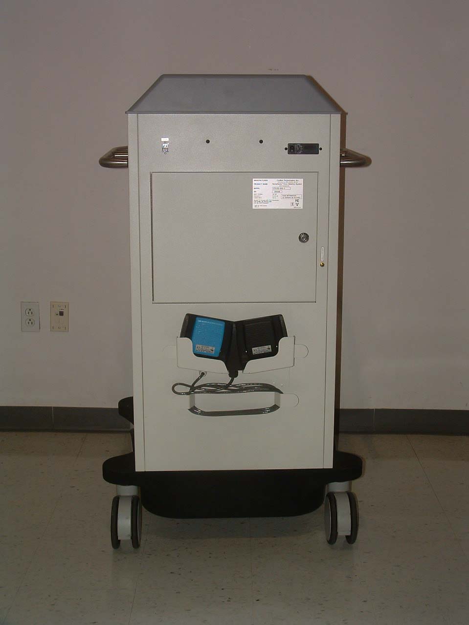
TUYCTIG250LCCryMed SprayGenix Cryo Ablation System

BIOMEC Inc.
CryMed SprayGenix Cryo Ablation System - FCC ID TUYCTIG250LC - BIOMEC Inc.
Click to zoom

Application Details

Equipment Class
DTS - Digital Transmission System
Date of Grant
Jun 04, 2006
Application Purpose
Original Equipment
Date of Application
Jun 01, 2006
Equipment Note
CryMed SprayGenix Cryo Ablation System
Frequency Range
2410.00000000 - 2470.00000000
Company
BIOMEC Inc.
Country
United States

Documents & Files

Select a file to view
Users Manual

↗

Block Diagram

↗

Cover Letter(s)

↗
↗
↗

External Photos

↗

ID Label/Location Info

↗

Internal Photos

↗

Operational Description

↗

RF Exposure Info

↗

Test Report

↗

Test Setup Photos

↗

Document Text

Text extracted from the exhibit documents filed with the FCC. Open a document above to read the original.

Users Manual

05.10.06 Draft Copy of Operator’s Manual i The information contained in this document may be confidential and/or legally privileged. Any unauthorized review, use, disclosure, dissemination, distribution, or copying of this communication, or any of its contents, is strictly prohibited. © 2005 CSA Medical, Inc., All Rights Reserved. OPERATOR MANUAL CryoSpray Ablation System Model #: CTI-G2-50L 05.10.06 Draft Copy of Operator’s Manual ii The information contained in this document may be confidential and/or legally privileged. Any unauthorized review, use, disclosure, dissemination, distribution, or copying of this communication, or any of its contents, is strictly prohibited. © 2005 CSA Medical, Inc., All Rights Reserved. Intellectual Property All Intellectual Property, as defined below, owned by or which is otherwise the property of CSA Medical, Inc. (CSA MEDICAL) or its respective suppliers relating to the CSA Medical’s CryoSpray Ablation TM System, including but not limited to, accessories, parts, or software relating thereto (the “CryoSpray Ablation TM System”), is proprietary to CSA MEDICAL and protected under federal laws, state laws, and international treaty provisions. Intellectual Property includes, but is not limited to, inventions (patentable or un-patentable), patents, trade secrets, copyrights, software, computer programs, and related documentation and other works of authorship. You may not infringe or otherwise violate the rights secured by the Intellectual Property. Moreover, you agree that you will not (and will not attempt to) modify, prepare derivative works of, reverse engineer, decompile, disassemble, or otherwise attempt to create source code from the software. No title to or ownership in the Intellectual Property is transferred to you. All applicable rights of the Intellectual Property shall remain with CSA MEDICAL and its suppliers. CSA Medical, Inc. Emerging Technology Center 1101 E. 33 rd Street, Third Floor - #A305 Baltimore, MD 21218 Phone: 443-921-8053 Internet Address: http://www.CSAmedical.com ©2005 CSA Medical, Inc., All Rights Reserved CSA Medical is a registered trademark of CSA Medical, Inc. and its related entities. Covered by one or more of the following patents: U.S. Patent No. 6,383,181, U.S. Serial No. 10/352,266 EP and Other U.S. and international patents are pending. 05.10.06 Draft Copy of Operator’s Manual iii The information contained in this document may be confidential and/or legally privileged. Any unauthorized review, use, disclosure, dissemination, distribution, or copying of this communication, or any of its contents, is strictly prohibited. © 2005 CSA Medical, Inc., All Rights Reserved. Disclaimer of Warranties: CSA MEDICAL PROVIDES NO EXPRESS WARRANTIES NOR GUARANTIES WHATSOEVER AND DISCLAIMS ALL IMPLIED WARRANTIES AS TO THE QUALITY OF THE EQUIPMENT AND SERVICES, NONINFRINGEMENT, MERCHANTABILITY OR FITNESS FOR ANY PARTICULAR USE OR PURPOSE. CSA MEDICAL PROVIDES NO INDEMNITY OF ANY KIND WHATSOEVER WITH RESPECT TO ANY EQUIPMENT OR SERVICES PROVIDED BY CSA MEDICAL. Limited Liability: CSA MEDICAL SHALL NOT BE LIABLE WITH RESPECT TO ANY SUBJECT MATTER OF THIS AGREEMENT, OR FOR ANY MEDICAL MALPRACTICE, UNDER ANY CONTRACT, NEGLIGENCE, STRICT LIABILITY OR OTHER LEGAL OR EQUITABLE THEORY FOR (a) ANY INCIDENTAL, CONSEQUENTIAL, SPECIAL OR PUNITIVE DAMAGES, OR (b) COST OF PROCUREMENT OF SUBSTITUTE GOODS, TECHNOLOGY OR SERVICES, AND IN ANY CASE SHALL NEVER BE LIABLE FOR MORE THAN THE AGGREGATE AMOUNT OF THE PAYMENTS MADE TO CSA MEDICAL. 05.10.06 Draft Copy of Operator’s Manual iv The information contained in this document may be confidential and/or legally privileged. Any unauthorized review, use, disclosure, dissemination, distribution, or copying of this communication, or any of its contents, is strictly prohibited. © 2005 CSA Medical, Inc., All Rights Reserved. This manual contains important information on proper use and maintenance of the SprayGenix TM Cryo Ablation System. ALL PERSONNEL INVOLVED IN THE USE AND MAINTENANCE OF THIS EQUIPMENT MUST CAREFULLY REVIEW AND COMPLY WITH THE WARNINGS, CAUTIONS, AND INSTRUCTIONS CONTAINED IN THIS MANUAL. These instructions are important to protect the health and safety of patients and personnel operating the Cryo-Ablator System and should be retained in a conveniently accessible area for quick reference. Complete instructions for setting up the device are presented in Chapter Three of this manual. This equipment has been tested and found to comply with the limits for a Class A digital device, pursuant to Part 15 of the FCC Rules. These limits are designed to provide reasonable protection against harmful interference when the equipment is operated in a commercial environment. This equipment generates, uses, and can radiate radio frequency energy and, if not installed and used in accordance with the instruction manual, may cause harmful interference to radio communications. Operation of this equipment in a residential area is likely to cause harmful interference in which case the user will be required to correct the interference at his own expense. Indications for Use The CryoSpray Ablation TM System is intended to be used as a cryosurgical tool for destruction of unwanted tissue gastroenterology, including the eradication of Barrett’s esophagus, with or without dysplasia. Service Information A thorough preventive maintenance program is essential to safe and proper system operation. This manual contains maintenance schedules and procedures that should be followed for satisfactory equipment performance. Advisory A summary of safety precautions to be observed when operating and servicing this system can be found in Chapter One of this manual. Do not operate or service the equipment until you have become familiar with this information. 05.10.06 Draft Copy of Operator’s Manual v The information contained in this document may be confidential and/or legally privileged. Any unauthorized review, use, disclosure, dissemi…

Text truncated - open the document above for the full version.

Block Diagram

GFSK Modulator Frequency Synthesizer GFSK Demodulator DSSS Baseband Serializer- Deserializer 13 MHz Matching NetworkAntenna Control Processor 2.4 GHz I/O Cypress Semiconductor CYWUSB6932 SPI Interface Control, Remote Unit Block Diagram

Cover Letter(s)

Non-Conformities FCC ID: TUYCTIG250LC (Ref # E06-0 00136-1) The items listed below represent requests for infor mation following review of this application. Furth er question may arise pending review of responses t o these items. OK # Non-Conformity or Comment Submitted Response Respondent / Date of Response Y 1 A request for confidentiality was not received. This item is to inform the applicant that certain items may be withheld from p ublic inspection in accordance with 47 CFR §0.457 and §0.459. No respo nse necessary for this item. Confidentiality Letter Uploaded 5/16/06 F2Labs Y 2 Please provide a complete set of internal photo s for the RF circuitry of this product as required by 2.1033(b)(7). Photos must b e of sufficient detail to read the silkscreen on the PCBs. Inclusion within the test report is convenient and common, however the FCC requires that this info rmation be provided separately to their website. Internal photos uploaded 5/23/06 F2Labs Y 3 Please provide a complete set of external photo s of all sides of this product as required by 2.1033(b)(7). Inclusion within the tes t report is convenient and common, however the FCC requires that this informat ion be provided separately to their website. External photos provided 6/2/06 F2Labs Y 4 Please provide a complete set of test setup pho tos for this product as required by 2.1033(b)(8). Inclusion within the test report is convenient and common, however the FCC requires that this information be p rovided separately to their website. Test setup photos provided 5/16/06 F2Labs Y 5 The provided form 731 lists the FCC ID as “ TUYCTIG250C “ while the test report lists, “TUYCTIG250L” and the provided l abel lists, “TUYCTIG250LC.” Please confirm the correct FCC for use with this application. TUYCTIG250LC confirmed, test report updated 5/23/06 F2Labs Y 6 The provided label location information is incomple te. It appears that the label is located on a movable part; the FCC ID must be placed on a non-removable portion of the enclosure. Please s upply further information regarding label placement, such as over all photo or description of the location. The console label is located on the door. The door hinge is affixed to the console with rivets; also, a door interlock switch would render the unit inoperable if the door were removed. TCB Comments: Label location information does not show correct label. 5/16/06 F2Labs Y 7 Please provide a label with labeling requiremen ts in accordance with 15.19, “This device complies with Part 15 of the FCC Rules . Operation is subject to the following two conditions: (1) this device may not cause harmful interference, and (2) this device must accept any interference received, including interference that may cause undesired ope ration..” Updated label provided 6/2/06 F2Labs Y 8 Please provide a users manual incorporating the statement required by 15.21. Updated users manual provided 6/2/06 F2Labs Y 9 The users manual does not contain required RF E xposure statements, caution to users regarding antenna separation distance. Pl ease revise users manual appropriately. Output below LT; RFX satisfied. 5/16/06 CKC CS and F2Labs Y 10 Please provide information on voltage variatio ns in accordance with 15.31(e). Found in updated te st report section 9.2 5/23/06 F2Labs Y 11 Please confirm power setting level 7 is the hi ghest output power. Power level 7 is the highest ou tput power for the CYWUSB6934 (REG_PA, address 0x23, bits 2-0). 5/16/06 F2Labs Y 12 Spurious emissions measurements do not explici tly state frequency range of investigation. Please clarify frequency range for measurements performed to 15.247(d), spurious emissions. Found in updated test report section 3 5/23/06 F2La bs Y 13 It is unclear from setup photos that ANSI C63. 4 requirements have been satisfied regarding loading of device. Please veri fy if all EUT ports are filled during testing. Found in updated test report section 4 5/23/06 F2La bs Y 14 Equipment incorporates use of an SMA Antenna c onnector for external antenna. This does not directly satisfy 47 CFR 15. 203 antenna connector requirements. Please submit information regarding demonstration of compliance with this requirement. The console antenna is mounted inside the chassis, well away from user accessibility. 5/16/06 F2Labs Y 15 Please provide RF Exposure statement contained in test report as a separate exhibit (in order to satisfy FCC upload requirement s). Please note that RF exposure statement is written with “>” sign which s hould probably have been “<”. Separate exhibit provided 5/23/06 F2Labs Y 16 CKC CS to perform uniqueness check on FCC ID. CKC CS performed FCC ID check. 5/23/06 CKC CS

External Photos

Console Front Console Rear Console Right Console Left

ID Label/Location Info

3.13 4.75 R .06 TYP. MANUFACTURER PRODUCT NAME SprayGenix Cryo Ablation System MODEL SN INPUT VOLTAGE FREQUENCY POWER INPUT PART No. 1210-001250 REV. 01 MADE IN U.S.A. CryMed Technologies, Inc. www.crymed.com 3225 Ellersie Ave., #B311, Baltimore, MD 21218 NOTES: 1. MATERIAL - .002" THICK. MATTE SILVER POLYESTER. WITH ADHESIVE BACKING. .001" CLEAR POLYETHYLENE OVERLAY. 2. CONTENT OF TEXT MUST MATCH DRAWING. ALL TEXT BLACK. 3. PRECISE FONT, FONT SIZE, SPACING, AND FORMAT MAY DIFFER SLIGHTLY FROM THAT DEPICTED. 4. SUPPLIER TO INSERT SERIAL NUMBERS PROVIDED WITH PURCHASE ORDER. 120 VAC 50/60 Hz 550 W CTI- G2-50L- C 00001 TM FUSE INFORMATION: (2) 5X20mm 5A SLO-BLO This device complies with Part 15 of the FCC Rules. Operation is subject to the following two conditions: (1) this device may not cause harmful interference, and (2) this device must accept any interference received, including interference that may cause undesired operation. FCC ID: TUYCTIG250LC D C B A A B C D BIOMEC Inc. CAD GENERATED DRAWING, DO NOT MANUALLY UPDATE SCALE 2:1 SIZE DWG. NO. B SHEET1OF1 UNLESS OTHERWISE SPECIFIED DIMENSIONS ARE IN INCHES TOLERANCES ARE: FRACTIONS DECIMALS ANGLES ± 1/64 .XX± .01 ± 1° .XXX± .005 MATERIAL FINISH SEE NOTE SEE NOTE DO NOT SCALE DRAWING 876 5 4 3 2 1 1 2 3 4 5 6 THE INFORMATION CONTAINED IN THIS DRAWING IS THE SOLE PROPERTY OF BIOMEC Inc. ANY REPRODUCTION IN PART OR WHOLE WITHOUT THE WRITTEN PERMISSION OF BIOMEC Inc. IS PROHIBITED. DIMENSIONS AND TOLERANCES TO BE INTERPRETTED ACCORDING TO ANSI STANDARD Y14.5M-1994 LABEL, REAR PANEL, CRYMED CRYOABLATOR 1210-001250-02

Internal Photos

F2LQ2271-02E Rev. 1 Page 1 of 3 May 12, 2006 CONSOLE: INTERNAL PHOTOGRAPHS Console Electronics Package: Shield Cover Removed Exposing Component Side of Printed Circuit Board Client: BIOMEC, Inc. Order Number: F2LQ2271 Model: CTI-G2-50L F2LQ2271-02E Rev. 1 Page 2 of 3 May 12, 2006 Console Electronics Package: Removed from Shield Case - Solder Side of Printed Circuit Board Client: BIOMEC, Inc. Order Number: F2LQ2271 Model: CTI-G2-50L F2LQ2271-02E Rev. 1 Page 3 of 3 May 12, 2006 Console Electronics Package: Installed in Console Unit with Centurion Antenna Connected (plastic top cover removed from console unit to expose electronics package)

Operational Description

Console PCB Operational Description The Console PCB is the principal controller for the system. Under microprocessor control, it processes analog and logical inputs to provide control to the system outputs, including the display, as well as to deliver cryogen to a catheter. The Console PCB also receives RF data from the handheld remote control, and transmits RF data to the remote display. Logical inputs and outputs to the console PCB are: • Pedal inputs • Keyboard inputs • Sensor inputs from the bleed, cryo delivery, and heater thermocouples; the pressure sensor, and the cryogen volume sensor • Logical I/O to the catheter • USB data I/O • Speaker outputs for operator alert tones • Emergency shutoff switch logical input • Solid-state relay output to the heater • Solenoid outputs for the pressure building coil, cryogen delivery, cryogen venting, and suction control. The microprocessor controlling console board operations utilizes an external clock source running at 22.1184 MHz. RF communication with the remote control and display utilize the Cypress CYWUSB6932 Wireless USB ® chip, operating in the 2.4 (2.40 to 2.483) GHz ISM band. The CYWUSB6932 utilizes Direct-Sequence Spread-Spectrum (DSSS) technology and Gaussian Frequency Shift Keying (GFSK) across 78 different 1 MHz channels in the ISM band. Frequency synthesis is performed on-chip from an external 13 MHz crystal. The CYWUSB6932 drives a Centurion WCR2400 ½-wave coaxial dipole antenna, which is connected to the board via a standard SMA connector. The PCB is fabricated from FR4 fiberglass, and is constructed in four layers: two signal, one power, and one ground. Except for the antenna, the PCB is contained within a metal enclosure. The enclosure is secured to chassis ground via an 18 AWG wire, and by four mounting screws, one at each corner of the enclosure.

RF Exposure Info

The output power level (<1.0 mW) on the Console Transmitter coupled with the low gain antenna (2.0 dBi) ensures that the user and/or general public will not be exposed to radio frequency energy levels in excess of FCC guidelines, per OET Bulletin 65 Supplement C Edition 01-01 June 2001.

Test Report

This report shall not be duplicated except in full without the written approval of F-Squared Laboratories. EMC007 Rev. 1 Report Number: F2LQ2271-02E Rev. 2 Page 1 of 57 Issue Date: May 16, 2006 F-Squared Laboratories 14333Kinsman Road Burton, OH 44021 (440) 834-8926 Fax: (440) 834-8914 For a CryMed Cryoablator Console Manufacturer: Testing Laboratory: BIOMEC, Inc. F-Squared Laboratories 1771 East 30 th Street 16740 Peters Road Cleveland, Ohio 44114 Middlefield, Ohio 44062 United States of America United States of America The Console, model CTI-G2-50L, for the BIOMEC/Crymed Cryoablator, was tested and was found to comply with the requirements of the Federal Communications Commission outlined in the Federal Register CFR 47, Part 15.247. The product was received on Nov. 21, 2005 and the testing was completed on Dec. 8, 2005. Evaluation Conducted By: Report Reviewed By: Kenneth P. Klann John Harrington EMC Engineer EMC Technical Manager Certification Test Report Client: BIOMEC, Inc. Order Number: F2LQ2271 Model: CTI-G2-50L EMC007 Rev. 1 Report Number: F2LQ2271-02E Rev. 2 Page 2 of 57 Issue Date: May 16, 2006 Table of Contents Section Title Page Cover Page 1 Table of Contents 2 1 Engineering Statement 3 2 List of Measurement Instrumentation 4 3 EUT Information and Data 5 4 EUT Configuration and Cables 6 5 FCC Part 15.403(f) – Digital Modulation 7 6 FCC Part 15.31(m) – Operating Frequencies 8 7 FCC PART 15.207(a) – Power Line Conducted Emissions 9 8 FCC Part 15.247(a)(2) – Bandwidth 10 9 FCC Part 15.247(b)(3) – Power Output 11 10 FCC Part 15.247(b)(5) – RF Safety 12 11 FCC Part 15.247(c) – Spurious Emissions 13 12 FCC Part 15.247(d) – Peak Power Spectral Density 18 13 Figures – Spectral Data Plots 19 14 Photos/Exhibits – Product Photos, Test Setups 48 Client: BIOMEC, Inc. Order Number: F2LQ2271 Model: CTI-G2-50L EMC007 Rev. 1 Report Number: F2LQ2271-02E Rev. 2 Page 3 of 57 Issue Date: May 16, 2006 1. ENGINEERING STATEMENT This report has been prepared on behalf of BIOMEC, Inc. to provide documentation for the testing described herein. This equipment has been tested and found to comply with Part 15.247 of the FCC Rules using ANSI C63.4 2003 standards. The test results found in this test report relate only to the items tested. 1.1. Equipment Under Test: BIOMEC/Crymed Cryoablator Console FCC ID: TUYCTIG250LC 1.2. Trade Name: BIOMEC 1.3. Model: BIOMEC/Crymed Cryoablator CTI-G2-50L Console 1.4. Power Supply: AC 120V, 60 Hz 1.5. Applicable Rules: CFR 47, Part 15.247, subpart C 1.6. Equipment Category: Radio Transmitter-DTS 1.7. Antenna: ½ Wave Coaxial Dipole (external) Centurion Model: NCR2400-SMA Gain: 2.0 dBi 1.8. Measurement Location: F-Squared Laboratories in Middlefield, Ohio. Site description and attenuation data are on file with the FCC's Sampling and Measurement Branch at the FCC Laboratory in Columbia, MD. 1.9. Measurement Procedure: All measurements were performed according to the 2003 version of ANSI C63.4 and recommended FCC procedure of measurement of DTS operating under Section 15.247 dated March 2005. A list of the measurement equipment can be found in Section 2. 1.10. Uncertainty Budget: Radiated Emission - Combined Uncertainty (+ or -) 2.24 dB; Expanded Uncertainty (+ or -) 4.48 dB 1.11. Engineering Certification: Client: BIOMEC, Inc. Order Number: F2LQ2271 Model: CTI-G2-50L EMC007 Rev. 1 Report Number: F2LQ2271-02E Rev. 2 Page 4 of 57 Issue Date: May 16, 2006 The undersigned of this report hereby state that the measurements shown in this application were made in accordance with the procedures indicated, and that the energy emitted by this equipment was found to be within the limits. The undersigned assume full responsibility for the accuracy and completeness of these measurements and further state that, on the basis of the measurements made, the equipment tested is capable of operation in accordance with the requirements of Part 15.247 of the FCC Rules under normal use and maintenance. 2. LIST OF MEASUREMENT INFORMATION Equipment Type Manufacturer Model Serial Number Calibration Due Date Thermohygrometer Oakton 32230-80 001 June 7, 2006 OATS Compliance Labs N/A 001 Aug. 24, 2006 Receiver Rohde & Schwarz Display, EASI-0-804- 8932-52; RF Unit, ESMI-RF 1032-5640-53 84982/015; 849152/005 Mar. 31, 2006 Horn Antenna Emco 3115 9809-5580 Apr. 6, 2006 Pre-Amplifier Hewlett Packard 83006A 310A00500 Oct. 20, 2006 Transient Limiter Hewlett Packard 11947A 3107A03325 Oct. 6, 2006 LISN 2 Solar 8028-50-TS-24-BNC 1128 Oct. 5, 2006 LISN 3 Solar 8028-50-TS-24-BNC 1129 Oct. 5, 2006 Active Loop Antenna AH Systems Inc SAS-562B 238 Jul 11, 2006 Antenna 2-OATS Sunol Sciences JB1 A101101 Apr. 15, 2006 Client: BIOMEC, Inc. Order Number: F2LQ2271 Model: CTI-G2-50L EMC007 Rev. 1 Report Number: F2LQ2271-02E Rev. 2 Page 5 of 57 Issue Date: May 16, 2006 3. EQUIPMENT UNDER TEST (EUT) INFORMATION AND DATA 3.1 Test Item Condition: The equipment to be tested was received in good condition. 3.2 Testing Algorithm: The Console Electronics Package was configured with Radio Test Firmware to permit frequency changes from low-mid-upper transmission channel using digital modulation (required for digital transmission systems) or unmodulated carrier. For RF antenna conducted tests, the Console Electronics Package antenna port was connected directly to the measurement equipment. For the conducted and radiated emissions tests, the electronics package was installed in the Console and fitted with the Centurion WCR2400-SMA antenna. All measurements were performed with the output power set to Level 7 (set in firmware). The highest emissions were recorded in the data tables. 3.3 Radiated Emission Testing on Open Area Test Site (OATS): The EUT was tested at a distance of 3.0 meters and 1.0 meter. The emissions were maximized by rotating the table and raising/lowering the antenna mounted on a 4.0 meter mast.* Both horizontal and vertical field components were measured. The output of the antenna was connected to the input of the receiv…

Text truncated - open the document above for the full version.

Test Setup Photos

F2LQ2271-02E Rev. 1 Page 1 of 5 May 12, 2006 TEST SETUP PHOTOGRAPHS Conducted Emissions Test Setup: Console Unit with DTS Transmitter – LISN Connection to Console Client: BIOMEC, Inc. Order Number: F2LQ2271 Model: CTI-G2-50L F2LQ2271-02E Rev. 1 Page 2 of 5 May 12, 2006 Conducted Emissions Test Setup: Console Electronics Package Direct Connection to Spectrum Analyzer Client: BIOMEC, Inc. Order Number: F2LQ2271 Model: CTI-G2-50L F2LQ2271-02E Rev. 1 Page 3 of 5 May 12, 2006 Antenna Conducted Test Setup: Console Electronics Package Direct Connection to Spectrum Analyzer – Overall Test Arrangement TOGRAPH OF POWER SUPPLY – Whole View Client: BIOMEC, Inc. Order Number: F2LQ2271 Model: CTI-G2-50L F2LQ2271-02E Rev. 1 Page 4 of 5 May 12, 2006 Radiated Emissions Test on OATS: Console Unit with DTS Transmitter – Plastic Top Cover Installed Client: BIOMEC, Inc. Order Number: F2LQ2271 Model: CTI-G2-50L F2LQ2271-02E Rev. 1 Page 5 of 5 May 12, 2006 (Radiated Emissions Test on OATS: Console Unit with DTS Transmitter – Plastic Top Cover Installed, cont’d)

Contact Information

Applicant

William A Hudgins(Engineering Program Manager)
[email protected]216-937-2800Fax: 216-937-2812

Technical Contact

BIOMEC, Inc.Bill Hudgins
[email protected]216-937-2800

1771 East 30th Street · Cleveland, Ohio · United States

Test Firm

F-Squared LaboratoriesJohn Harrington
[email protected]440-834-8926Fax: 440-834-8914

Technical Specifications

#Rule PartsFrequency RangePower Output
115C2.41 GHz - 2.47 GHz665.00 µW
Confidentiality
Long Term
Grant Notes
Power listed is conducted. Approved for use only with antenna(s) as listed in this filing.

Other Applications from BIOMEC Inc.

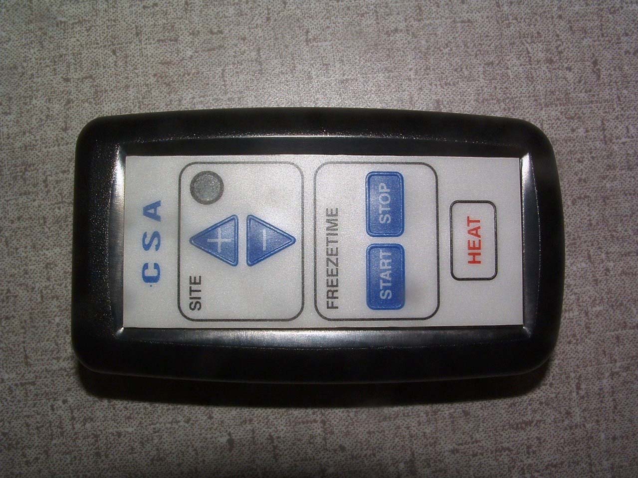
CryMed Cryoablator Hand-Held Remote - FCC ID TUYCTIG250R - BIOMEC Inc.
TUYCTIG250R

CryMed Cryoablator Hand-Held Remote

Jun 04, 2006

Equipment Class

DTS - Digital Transmission System