TV81500-3Networking Device
The L.S. Starrett Company
Click to zoom
Application Details
- Equipment Class
- DXX - Part 15 Low Power Communication Device Transmitter
- Date of Grant
- Jan 19, 2006
- Application Purpose
- Original Equipment
- Date of Application
- Jan 19, 2006
- Equipment Note
- Networking Device
- Frequency Range
- 916.50000000 - 916.50000000
- Company
- The L.S. Starrett Company
- Country
- United States
Documents & Files
Document Text
Text extracted from the exhibit documents filed with the FCC. Open a document above to read the original.
Users Manual
DataSure™ Wireless Manager Operator’s Manual DataSure™ Operators Manual 2 PT 6***** DataSure™ is a trademark of the L.S. Starrett Company. All rights reserved. DataSure™ Operators Manual 3 PT 6***** Contents Section 1 Overview 1.1 Introduction 1.2 Features 1.3 Care and Maintenance 1.4 Hardware Definitions 1.5 Network Elements and Topologies 1.5.1 Routing Network – MESH 1.5.2 Routing Network – STRING 1.5.3 Hybrid MESH - STRING Networks 1.5.4 Network Options 1.5.5 Determining the Network Layout 1.5.5.1 Steps to layout your network 1.5.5.2 Tips for best performance 1.6 Software Definitions 1.7 Installation 1.7.1 Initial Startup 1.7.2 Device Identification 1.7.3 Virtual Multiplexers 1.7.4 External Application Setup 1.7.5 Basic Network Administration Section 2 Operation 2.1 Data Collection 2.1.1 Quick Start 2.1.2 Data Logging 2.1.3 Applications 2.2 Remote Network Monitoring 2.3 Advanced Network Administration Section 3 Troubleshooting 3.1 Common Problems and Solutions 3.2 Recommended Use Policies 3.3 RF Does & Don’ts 3.4 Monitoring Device Statistics Appendix A: Application Interfaces Appendix B: LED Blink Tables Appendix x: Network Monitor DataSure™ Operators Manual 4 PT 6***** DataSure™™™ Operators Manual 5 PT 6***** Section 1 Overview 1.1 Introduction The Starrett DataSure™ wireless network is designed to allow the transfer of data from electronic measuring tools to computers where measurements can either be easily logged or conveyed to an SPC software package. The wireless network environment allows tool operators to move freely without the constraints of data cables. The DataSure™ wireless manager software provides a convenient user interface for network configuration, management, and inspection. Since many SPC packages are intended for use with wired data collection systems that utilize multiplexers to connect a variety of tools together through an RS232 communications port, the DataSure™ software utility also fully emulates this approach. The DataSure™ utility software enables operators to configure their wireless network, and manage the flow of tool data to their target applications. Measurements can be initiated either by the operator of the tool or solicited via computer software. The following statement applies to each of the DataSure™ wireless devices (EndNode, Router, Gateway): This device complies with Part 15 of the FCC Rules. Operation is subject to the following two conditions: (1) this device may not cause harmful interference, and (2) this device must accept any interference received, including interference that may cause undesired operation. Changes or modifications not expressly approved by the L.S. Starrett Company could void the user’s authority to operate the equipment. 1.2 Features • 916 MHz RF technology • Freedom of movement and from data cables • Up to 32 tools per virtual multiplexer • Up to 5 virtual multiplexers • A variety of exportable log file formats • USB or RS 232 Gateway - PC interface • Operating distance up to 25 meters (80 feet) for EndNodes • Broadcast range up to 30 meters (97 feet) for Gateway and Routers • System status feedback on the EndNode, including acknowledge of data received • Adapts to electronic tools from various manufacturers • No line-of-sight limitation • Temporary data retention at the EndNode while outside the network • Routers enlarge network range and improve robustness against radio interference • Optional wall mount for Routers • Routers equipped with a rechargeable battery backup DataSure™ Operators Manual 6 PT 6***** • EndNodes offer a choice of battery selection (CR2450 or CR2477) • Gateway and Router antenna can be angled and swiveled to improve reception 1.3 Care & Maintenance • Cleaning and handling instructions External plastic surfaces of EndNodes, Routers, and Gateways may be cleaned with Isopropyl Alcohol and a non-abrasive cloth. Care should be taken not to wet internal surfaces or conductive cable ports. Antennae are delicate, and should be handled with caution. • Plug in cautions • Environmental bounds of use, humidity, temp, etc. • Battery replacement 1.4 Hardware Definitions • Gateway The Gateway is a radio device which provides a point of entry for the wireless network to interface with software running on PC. Only one Gateway may be used for a group of network elements. There are two status indicators on the Gateway; one is a power indicator, and the other shows radio activity. The red is a power indicator, and the green shows radio activity. The Gateway can be turned on or off via a sliding power switch. Gateways are available with either an RS232 DB-9 connector, or a USB port. Only RS232 enabled Gateways must be powered via an external AC wall adapter (included). The power cable may be looped around the posts located near the power entry jack on the rear of the Gateway. This provides strain-relief to guard against accidental shutoff if the cable should become snagged and pulled away unintentionally. • Router Routers are radio devices which provide robustness, range, and scalability to the wireless network. They serve as intermediary steps between the EndNodes and a Gateway. Routers should be installed within range of a Gateway, or else within reaching distance of other Routers. EndNodes can be carried freely throughout a network environment bounded by the overlapping ranges of Routers and the Gateway. Adding more Routers to a network-enabled space further strengthens a network by providing multiple paths for data transmissions to follow. Routers operate automatically; they require no further operation beyond proper placement, antenna orientation, and supplying of power. There are two status indicators on the Router; one is a power indicator, and the other shows radio activity. The Router can be turned on or off via a sliding power switch. Routers are powered via an external AC wall adapter (included), and are also equipped with a rechargeable battery backup. The power cables may be looped around the posts locat…
Text truncated - open the document above for the full version.
Cover Letter(s)
QUICK DATA SHEET JJB Series Ultra-Compact Antenna DESCRIPTION The JJB-Series packs near the performance of a conventional monopole into an incredibly compact 7mm-diameter package. These antennas are ideal for any OEM application requiring a compact, cosmetically attractive, low-cost antenna solution. The antenna features a through-hole feedline which attaches directly to a user’s PCB. Internal or external mounting is possible. FEATURES SPECIFICATIONS PHYSICAL DIMENSIONS This is a preliminary data sheet. Recipient understands any or all of the above specifications are subject to change without notice and proceeds with integration at own risk. For additional information: Linx Technologies 1-800-736-6677 Revised 4/29/03 ■Ultra-Compact ■Very Low Cost ■High-Performance (-1dBi Typical) ■Low VSWR (<2.0) ■Good Usable Bandwidth (900-930MHz) ■Easily Concealed Internally ■Direct PCB Mount Ø 0.276" (7) Ø 0.059" (1.5) Ø 0.0393" (1) 0.354" (9) 0.216" (5.5) 0.216" (5.5) 0.570" (14.5) 0.33" (7.6) Ø 0.28" (7) Ø 0.06" (1.5) Ø 0.10" (2.5) Ø 0.04" (1) 0.35" (9) All measurements made using 1.5” x 3.5” groundplane counterpoise. TYPICAL SWRSMITH CHART Wavelength:1/4 Wave Designed for Match:50Ω Typical VSWR:Center <1.7 Over Bandwidth <2.1 Typical Center:916MHz Usable Bandwidth:30MHz (900-930MHz) Typical Gain -1dBi (Relative to Isotropic) Element:Precision Helical 1:1.8423 902MHz 2:1.2685 916MHz 3:1.4181 928MHz 1:26.69Ω -12.951Ω 902MHZ 2:40.971Ω -2.5352Ω 916MHz 3:65.828Ω -13.957Ω 928MHz NOTE:For hand application only.Flux Feed-Pin prior to soldering. Solder quickly to avoid damage. ANT-916-JJB-RA ANT-916-JJB-ST P ART #DESCRIPTION ANT-***-JJB-RAJJB Perm.Ultra-Miniature ANT-***-JJB-STStraight version of JJB ***= 868, 916-(902-928MHz) ORDERING INFORMATION ANT-***-JJB-STANT-***-JJB-RA Straight VersionRight-Angle Version
External Photos
REPORT: EF0764-3 FCC ID: TV81500-3 EXHIBIT: External Photos MODEL: 1500-3 _____________________________________________________________ _____________________________________________________________ Curtis-Straus LLC • 527 Great Road • Littleton, MA • TEL (978) 486-8880 • FAX (978) 486-8828 Page 1 of 1
ID Label/Location Info
TECHNICAL DATA SHEET TT704 GLOSSY SILVER POLYESTER DESCRIPTION: TT704 is a top coated glossy silver polyester film. It is coated with a permanent acrylic adhesive and backed with a #50 Kraft release liner. USES: Ideal for UL/CSA finished product nameplates and asset identification. This high-performance material is designed for application requiring excellent solvent and scratch resistance. FEATURES: Smudge and abrasion resistant thermal images using resin-based ribbons. Face stock resists tearing, abrasion, and heat. High performance adhesive bonds to a wide range of surfaces. ADHESIVE: 1.0 mil acrylic SERVICE TEMPERATURE -40ºF -302ºF MINIMUM APPLICATION TEMPERATURE: 50ºF UL &CSA # UL# MH19992 CSA#204415 ** TT704, like all other pressure-sensitive materials, must be tested under the actual end use conditions.
ID Label/Location Info
Starrett Model No. 1500-1-UN Group No: 31.140 ID: 251.41 FC FCC ID :TV81500-1 This device complies with part 15 of FCC Rules. Operationis subject to the following two conditions: 1. This device may not cause harmful interference and 2. This device must accept an y interference received, including interference that may cause undesired operation. IC: 6164A-15001AMERICAN MADE Gateway Bottom Router Bottom Starrett Wireless Model 1500 FCC Label Diagram FCC ID: TV81500-3 IC: 6164A-15003 Group No: 31.140 / 21.101 Model No: 1500-3-1N End Node R C Starrett Model No. 1500-2-RN Group No: 31.140 ID: 251.41 FC FCC ID :TV81500-2 This device complies with part 15 of FCC Rules. Operationis subject to the following two conditions: 1. This device may not cause harmful interference and 2. This device must accept an y interference received, including interference that may cause undesired operation. IC: 6164A-15002AMERICAN MADE R C
Internal Photos
REPORT: EF0764-3 FCC ID: TV81500-3 EXHIBIT: Internal Photos MODEL: 1500-3 _____________________________________________________________ _____________________________________________________________ Curtis-Straus LLC • 527 Great Road • Littleton, MA • TEL (978) 486-8880 • FAX (978) 486-8828 Page 1 of 3 REPORT: EF0764-3 FCC ID: TV81500-3 EXHIBIT: Internal Photos MODEL: 1500-3 _____________________________________________________________ _____________________________________________________________ Curtis-Straus LLC • 527 Great Road • Littleton, MA • TEL (978) 486-8880 • FAX (978) 486-8828 Page 2 of 3 REPORT: EF0764-3 FCC ID: TV81500-3 EXHIBIT: Internal Photos MODEL: 1500-3 _____________________________________________________________ _____________________________________________________________ Curtis-Straus LLC • 527 Great Road • Littleton, MA • TEL (978) 486-8880 • FAX (978) 486-8828 Page 3 of 3
Test Report
Test Report Report No EF0764-3 Client LS Starrett 121 Crescent Street Athol, MA 01331 Phone 978-249-3551 FRN 0014116503 RSS-210 Issue 6; FCC Part 15.249 Model 1500-3 FCC ID TV81500-3 IC 6164A-15003 Equipment Type Low Power Communications Device Transmitter Equipment Code DXX Emission Designator K1D Results As detailed within this report Prepared by _____________________ David Harris – Test Engineer Authorized by __________________________ Michael Buchholz – EMC Manager Issue Date 1/17/06 Conditions of issue This Test Report is issued subject to the conditions stated in ‘terms and conditions’ section of this report. Curtis-Straus LLC is accredited by the American Association for Laboratory Accreditation for the specific scope of accreditation under Certificate Number 1627-01. This report may contain data which is not covered by the A2LA accreditation. _____________________________________________________________ LLC • 527 Great Road • Littleton, MA • TEL (978) 486-8880 • FAX (978) 486-8828 Curtis-Straus REPORT: EF0764-3 FCC ID: TV81500-3 IC: 6164A-15003 _____________________________________________________________ _____________________________________________________________ Table of Contents Summary.........................................................................................................................3 Test Methodology............................................................................................................3 Statement of Conformity..................................................................................................4 EUT Configuration...........................................................................................................5 Fundamental Measurement............................................................................................6 Band Edge Measurements..............................................................................................6 Radiated Spurious Emissions.........................................................................................7 AC Line Conducted Emissions........................................................................................7 Voltage Variations...........................................................................................................7 Test Equipment Used......................................................................................................8 Terms And Conditions...................................................................................................10 LLC • 527 Great Road • Littleton, MA • TEL (978) 486-8880 • FAX (978) 486-8828 Page 2 of 14 Curtis-Straus REPORT: EF0764-3 FCC ID: TV81500-3 IC: 6164A-15003 _____________________________________________________________ _____________________________________________________________ Summary This test report supports an application for certification of a transmitter operating pursuant to 47 CFR 15.249 and RSS-210(A2.9). The product is the EndNode, MN 1500-3. It is a transmitter that operates at 916.5 MHz. Test Methodology Radiated emissions testing are performed according to the procedures specified in ANSI C63.4 (2003) and RSS-GEN. Emissions were maximized by rotating the device around three orthogonal axes as well as varying the test antenna’s height and polarity. The environmental conditions are shown below. Date Temperature (°c) Humidity (%) 10/20/05 24.2 29 10/28/05 23.4 25 Frequency range investigated: 0.15MHz – 10GHz Measurement distance: 30MHz – 3GHz 3m 3 – 10GHz 1m A fresh battery was used for testing. LLC • 527 Great Road • Littleton, MA • TEL (978) 486-8880 • FAX (978) 486-8828 Page 3 of 14 Curtis-Straus REPORT: EF0764-3 FCC ID: TV81500-3 IC: 6164A-15003 _____________________________________________________________ _____________________________________________________________ Statement of Conformity The EndNode, MN 1500-3 has been found to conform to the following parts: RSS-GEN RSS 210 Part 15 Comments 5.3 15.15(b) There are no controls accessible to the user that vary the output power. 5.2 15.19 The label is shown in the label exhibit. 7.1.5 15.21 Information to the user is shown in the instruction manual exhibit. 15.27 No special accessories are required for compliance. 7.1.4 15.203 The antenna for this device is hardwired to the PCB. 2.6 15.205 15.209 The fundamental is not in a Restricted band and the spurious and harmonic emissions in the Restricted bands comply with the general emission limits of 15.209. 7.2.2 15.207 EUT meets the AC Line conducted emissions requirements of 15.207. A2.9 15.249 The unit complies with the requirements of 15.249 LLC • 527 Great Road • Littleton, MA • TEL (978) 486-8880 • FAX (978) 486-8828 Page 4 of 14 Curtis-Straus REPORT: EF0764-3 FCC ID: TV81500-3 IC: 6164A-15003 _____________________________________________________________ _____________________________________________________________ EUT Configuration EUT Configuration Work Order: F0764 Company: LS Starrett Company Address: 121 Crescent Street Athol, MA 01331 Contact: John Belliveau MNSN EUT: EndNode - Starrett Opto Connector1500-3-NSample 1 EUT Description: Endnode EUT Max Fre quency: 916.6MHz Support Equipment:MNSN None EUT Cables:QtyShielded?LengthFerrites Tool extension cable1Yes0.1mNone Unpopulated EUT Ports: QtyReason None Software / Operating Mode Description: EUT was running in the transmit mode specified by the test. The modes available are: sleep, ASK transmit, OOK transmit, and receive. Unless otherwise stated the EUT was operating in ASK transmit mode which is the maximum transmitted power level mode. LLC • 527 Great Road • Littleton, MA • TEL (978) 486-8880 • FAX (978) 486-8828 Page 5 of 14 Curtis-Straus REPORT: EF0764-3 FCC ID: TV81500-3 IC: 6164A-15003 _____________________________________________________________ _____________________________________________________________ Fundamental Measurement LIMIT QuasiPeak: 93.9dBμV/m @ 3m [15.35(b)] MEASUREMENTS Fundamental C…
Text truncated - open the document above for the full version.
Test Setup Photos
REPORT: EF0764-3 FCC ID: TV81500-3 EXHIBIT: Setup Photos MODEL: 1500-3 _____________________________________________________________ _____________________________________________________________ Curtis-Straus LLC • 527 Great Road • Littleton, MA • TEL (978) 486-8880 • FAX (978) 486-8828 Page 1 of 2 REPORT: EF0764-3 FCC ID: TV81500-3 EXHIBIT: Setup Photos MODEL: 1500-3 _____________________________________________________________ _____________________________________________________________ Curtis-Straus LLC • 527 Great Road • Littleton, MA • TEL (978) 486-8880 • FAX (978) 486-8828 Page 2 of 2
Contact Information
Applicant
John Belliveau Belliveau(Sr. Project Engineer)
Test Firm
BUREAU VERITAS CONSUMER PRODUCTS SERVICES, INC.Ozgur Ozturk
[email protected]978-486-8880
Technical Specifications
| # | Rule Parts | Frequency Range | Power Output |
|---|---|---|---|
| 1 | 15C | 916.5 MHz - 916.5 MHz | - |
Other Applications from The L.S. Starrett Company

TV81500-2
Jan 19, 2006Networking Device
Equipment Class
DXT - Part 15 Low Power Transceiver, Rx Verified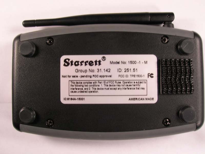
TV81500-1
Jan 19, 2006Networking Device
Equipment Class
DXX - Part 15 Low Power Communication Device Transmitter