FCCID.CO- FCC ID Database
HomeCompaniesEquipment ClassesSearch

© 2026 FCC ID Database. All rights reserved.

AboutContactData sourced from FCC public records
  1. Home/
  2. Alico Systems Incorporated/
  3. TVQ-U24A

TVQ-U24A2.4 GHz Wireless Network Equipment

Alico Systems Incorporated
2.4 GHz Wireless Network Equipment - FCC ID TVQ-U24A - Alico Systems Incorporated
Click to zoom

Application Details

Equipment Class
DTS - Digital Transmission System
Date of Grant
Aug 10, 2006
Application Purpose
Original Equipment
Date of Application
Aug 10, 2006
Equipment Note
2.4 GHz Wireless Network Equipment
Frequency Range
2412.00000000 - 2462.00000000
Company
Alico Systems Incorporated
Country
United States

Documents & Files

Select a file to view
Users Manual

↗
↗

Block Diagram

↗

Cover Letter(s)

↗
↗
↗
↗
↗

External Photos

↗
↗
↗
↗

ID Label/Location Info

↗
↗
↗

Internal Photos

↗
↗
↗
↗

RF Exposure Info

↗

Test Report

↗
↗

Test Setup Photos

↗

Document Text

Text extracted from the exhibit documents filed with the FCC. Open a document above to read the original.

Users Manual

1 Wireless Network Equipment (WNE) Freedom Series: Types AP24, BR24, CP24 Models: 24-SB-07M, 24-LB-15O, 24-LB-20S Freedom Series: Types AP58, BR58, CP58 Models: 58-LB-09M, 58-LB-15O, 58-LB-17S, 58-LB-32D Instruction Manual Alico Systems Inc 2461 W. 205 th Street, Suite B105 Torrance, California 90501-1464 Telephone: 310-781-9500 www.alicosystems.com 2 Notices FCC Notice: Part 15 Notice: This device complies with Part 15 of the FCC Rules. Operation is subject to the following two conditions: (1) this device may not cause harmful interference, and (2) this device must accept any interference received, including interference that may cause undesired operation. Any changes or modifications not expressly approved by the party responsible for compliance could void the user's authority to operate the equipment. Class B Digital Device: This equipment has been tested and found to comply with the limits for a Class B digital device, pursuant to Part 15 of the FCC Rules. These limits are designed to provide reasonable protection against harmful interference in a residential installation. This equipment generates, uses and can radiate radio frequency energy and, if not installed and used in accordance with the instructions, may cause harmful interference to radio communications. However, there is no guarantee that interference will not occur in a particular installation. If this equipment does cause harmful interference to radio or television reception, which can be determined by turning the equipment off and on, the user is encouraged to try to correct the interference by one or more of the following measures: „ Reorient or relocate the receiving antenna. „ Increase the separation between the equipment and receiver. „ Connect the equipment into an outlet on a circuit different from that to which the receiver is connected. „ Consult the dealer or an experienced radio/TV technician for help. 3 Scope: This equipment is intended to be installed by professional trained installers familiar with the appropriate FCC Regulations and Local Building Codes. The equipment is designed to be installed on a pole or as a wall mount unit. While the unit is in operation the WNE antenna shall be at least 20 cms away from all persons. Setup Instructions: Package Contains: 1. AP24/AP58 Access Point-Bridge-CPE 2. Power over Ethernet Injector 3. 48VDC Power Supply 4. AC power cord 5. RJ45 Feed-Through Assembly 6. CD Containing the “WinBox” application software to provision the AP24/AP58 Access Point - Bridge and a PDF version of this “Startup Instructions for AP24/AP58” What You Need to Get Started: • You need to provide 2 straight patch segments of CAT-5e Ethernet cable with RJ45 connectors on each end. You may also need a crossover cable to configure the AP24/AP58 if you are connecting directly to a PC. • The first CAT-5e patch cable will be used to connect the AP24/AP58 to the POE module. This cable needs to have RJ45 connectors preferably with no boots. Having a boot on the RJ45 cable on the AP24/AP58 side may prevent you to properly install the Feed-Through Assembly. See instructions on the next slide. • CAUTION DO NOT USE A CROSS OVER CABLE BETWEEN THE AP24/AP58 AND THE POE MODULE. YOU WILL PERMANENTLY DAMAGE THE AP24/AP58. • The second CAT-5e patch cable will be used to connect the POE module to your Switch/Router. If you are connecting the POE module directly to your PC for setup you need to use a crossover cable. The total length for both CAT-5e cable segments must not exceed 300 feet (~90 meters). • The options to setup the AP24/AP58 would be to connect your PC directly to the POE module (using a crossover cable), through a switch (using a patch cable) or wireless. To connect using the wireless IF set your PC/Laptop SSID to AP24/AP58 and click on connect. Once connected you can follow the instructions shown on following pages using the WinBox. • The AP24/AP58 is shipped with a default private address 192.168.0.239. You can change this IP address or setup multiple IP addresses for the AP24/AP58. • In order to get started quickly the AP24/AP58 is shipped with an internal bridge setup (called “bridge1”) between the Wireless LAN Port and the Ethernet Port. This “bridge1 is setup with the default IP address 192.168.0.239. You can also setup the unit in the router mode if needed to get full routing, DHCP server, capabilities etc. The Wireless LAN is setup in the infrastructure AP mode with a SSID of “AP24” (or AP58). 4 WNE Wiring Diagram The wireless network equipment is powered by a 48 VDC Power over Ethernet power supply/injector module. The following steps should be accomplished to power the WNE: 1. Install the WNE enclosure either on a pole or to a wall. 2. Follow the instructions in the next section to assemble the Ethernet weatherproof cable feed through assembly. 3. Connect one end of a patch (straight through) CAT 5e Ethernet cable to the AP24/58 through the Feed through assembly. 4. Connect the other end of the CAT5e cable to the power and data port of the Power Over Ethernet Module. 5. Locate the LAN Switch in your wiring closet and connect a patch (straight through) CAT 5e cable from the IN/DATA port of the Power over Ethernet module to a LAN Switch port. 6. Last connect the 48VDC power supply to the Power Over Ethernet injector. Using the supplied AC power cord connect the power supply to the AC. The unit operates on 110/240 VAC, 50/60 Hz. Figure 1 Connection Diagram 5 Antenna Installation Requirements: The installer shall ensure that the following antenna gains are not exceeded when installing the Alico Wireless Networking Equipment with an external antenna. Freedom Series Antenna Certifications: The Alico Systems Freedom Series Access Points, Bridges and CPEs are certified with the following antenna configurations. 1. 2.4 GHz Frequency Band (2400 to 2483.5 MHz) Freedom Series Types AP24, BR24, CP24 Antenna Type Model Designation Maximum Antenna Gain (dBi) Mobile Omni 24-SB-07M 7 Omni 24-LB-15O 15 Sector …

Text truncated - open the document above for the full version.

Users Manual

1 Wireless Network Equipment Optima Series: Types AP24, BR24, CP24 Models: 24-AE-19F Optima Series: Types AP58, BR58, CP58 Models: 58-AE-26F Instruction Manual Alico Systems Inc 2461 W. 205 th Street, Suite B105 Torrance, California 90501-1464 Telephone: 310-781-9500 www.alicosystems.com 2 Notices FCC Notice: Part 15 Notice: This device complies with Part 15 of the FCC Rules. Operation is subject to the following two conditions: (1) this device may not cause harmful interference, and (2) this device must accept any interference received, including interference that may cause undesired operation. Any changes or modifications not expressly approved by the party responsible for compliance could void the user's authority to operate the equipment. Class B Digital Device: This equipment has been tested and found to comply with the limits for a Class B digital device, pursuant to Part 15 of the FCC Rules. These limits are designed to provide reasonable protection against harmful interference in a residential installation. This equipment generates, uses and can radiate radio frequency energy and, if not installed and used in accordance with the instructions, may cause harmful interference to radio communications. However, there is no guarantee that interference will not occur in a particular installation. If this equipment does cause harmful interference to radio or television reception, which can be determined by turning the equipment off and on, the user is encouraged to try to correct the interference by one or more of the following measures: „ Reorient or relocate the receiving antenna. „ Increase the separation between the equipment and receiver. „ Connect the equipment into an outlet on a circuit different from that to which the receiver is connected. „ Consult the dealer or an experienced radio/TV technician for help. 3 Scope: This equipment is intended to be installed by professional trained installers familiar with the appropriate FCC Regulations and Local Building Codes. The equipment is designed to be installed on a pole or as a wall mount unit. While the unit is in operation the WNE antenna shall be at least 20 cms away from all persons. Setup Instructions: Package Contains: 1. AP24/58 Access Point-Bridge 2. Power over Ethernet Injector 3. 48VDC Power Supply 4. AC power cord 5. RJ45 Feed-Through Assembly 6. CD Containing the “WinBox” application software to provision the AP24/58 Access Point - Bridge and a PDF version of this Instruction Manual. What You Need to Get Started: • You need to provide 2 straight patch segments of CAT-5e Ethernet cable with RJ45 connectors on each end. You may also need a crossover cable to configure the AP24/58 if you are connecting directly to a PC. • The first CAT-5e patch cable will be used to connect the AP24/58 to the POE Injector module. This cable needs to have RJ45 connectors preferably with no boots. Having a boot on the RJ45 cable on the AP24/58 side may prevent you to properly install the Feed-Through Assembly. See instructions on the next slide. • CAUTION DO NOT USE A CROSS OVER CABLE BETWEEN THE AP24/58 AND THE POE MODULE. YOU WILL PERMANENTLY DAMAGE THE AP24/58. • The second CAT-5e patch cable will be used to connect the POE module to your Switch/Router. If you are connecting the POE module directly to your PC for setup you need to use a crossover cable. The total length for both CAT-5e cable segments must not exceed 300 feet (~90 meters). • The options to setup the AP24/AP58 would be to connect your PC directly to the POE module (using a crossover cable), through a switch (using a patch cable) or wireless. To connect using the wireless interface set your PC/Laptop SSID to AP24 (or AP58) and click on connect. Once connected you can follow the instructions shown on following pages using the WinBox. • The AP24/AP58 is shipped with a default private address 192.168.0.239. You can change this IP address or setup multiple IP addresses for the AP. • In order to get started quickly the AP is shipped with an internal bridge setup (called “bridge1”) between the Wireless LAN Interface and the Ethernet Interface. This “bridge1 is setup with the default IP address 192.168.0.239. You can also setup the unit in the router mode if needed to get full routing, DHCP server, capabilities etc. The Wireless LAN is setup in the infrastructure AP (AP-bridge) mode with a SSID of “AP24” (or AP58). 4 WNE Wiring Diagram The wireless network equipment is powered by a 48 VDC Power over Ethernet power supply/injector module. The following steps should be accomplished to power the WNE: 1. Install the WNE Antenna Enclosure either on a pole or to a wall. 2. Follow the instructions in the next section to assemble the Ethernet weatherproof cable feed through assembly. 3. Connect one end of a patch (straight through) CAT 5e Ethernet cable to the AP24/58 through the Feed through assembly. 4. Connect the other end of the CAT5e cable to the power and data port of the Power Over Ethernet Module. 5. Locate the LAN Switch in your wiring closet and connect a patch (straight through) CAT 5e cable from the IN/DATA port of the Power over Ethernet module to a LAN Switch port. 6. Last connect the 48VDC power supply to the Power Over Ethernet injector. Using the supplied AC power cord connect the power supply to the AC. The unit operates on 110/240 VAC, 50/60 Hz. Figure 1 Connection Diagram 5 Cable Feed-through Assembly Step 1: Use a Cat 5/6 cable with a open RJ45 connector without a boot. • Do not tighten compression gasket until you are finalizing the installation. The gasket should only be fully tightened once. Thorough inspection of the compression fitting should be done if it is re- used. • After assembly, we recommend completely wrapping the Feed-Through-Assembly using waterproof outdoor electrical tape as a secondary water barrier. 6 Starting Winbox Using the MAC Address Note: In order to connect using the MAC address your PC must be on different subnet than the default AP24 IP addr…

Text truncated - open the document above for the full version.

Cover Letter(s)

1 6 August 2006 CKC Certification Services TCB No: US0103 4933 Sierra Pines Drive Mariposa, CA 95338 Subject: Application for Limited Modular Approval of 2.4 GHz Transmitter FCC ID: TVQ-U24A Reference: FCC Registration Number 0014119408 Alico Systems Inc Grantee Code: TVQ Dear TCB: Alico Systems is applying for Limited Modular Approval of a 2.4GHz Transmitter Module under FCC Part 15 rules. Alico is utilizing a previously FCC certified unmodified product from Ubiquity Networks FCC ID: SWX-SR2 (datasheet attached) as our transmitter module. Alico Systems is a systems manufacturer/OEM and utilizes components/modules from best of breed vendors to develop our end product. This proposed modular transmitter (TVQ-U24A) as configured and tested will be exclusively used within Alico Systems end products. We intend to only sell this modular transmitter as an embedded part of an Alico product line in applications such as Wireless Access Point, Base Station, Wireless Bridge, Mesh Network, Subscriber CPE, etc. We will not sell the modular transmitter as a standalone product. Compliance with Modular Transmitter Requirements: Requirement #1: Comply. The modular transmitter is in the form of a mini-PCI card and includes appropriate shielding on board and no external shielding is required. This was demonstrated by testing the transmitter without any enclosures and was found in compliance with the Part 15 limits. Requirement #2: Comply. The modular transmitter is based on the Atheros AR5004G chipset, the RF section is based on a single chip radio AR2112 which only interfaces to the baseband chip AR5213. The modulation and data rates are controlled by the baseband chip. The entire chip set supports the IEEE 802.11 b/g protocol and the modulation type and data rates are as per the IEEE standard. The interface to the modular transmitter is through a PCI bus specification only. S Y S T E M S , I N C . 2461 W. 205 th Street Suite B105 Torrance, CA 90501-1464 562-436-1510 tel 562-436-0039 fax www.alicosystems.com 2 Requirement #3: Comply. The modular transmitter is powered by a 3.3V DC power supply. This power supply requirement is part of the PCI specification (used for the transmitter mini PCI card). In addition to the 3.3VDC power, the modular transmitter generates onboard 2.5VDC and 1.8VDC required for the AR5004G chipset. The microprocessor mother board which hosts the modular transmitter has a DC to DC power supply which generates the 3.3VDC. The entire power supply is tightly controlled within the sealed enclosure. The end user or installer will have no control to vary the power supply to the transmitter. Requirement #4: Comply. Alico plans to sell two configurations. One configuration will include an integrated antenna which cannot be replaced. The second configuration utilizes an external antenna. Alico has tested and plans to offer 4 types of antennas for the 2.4 GHz transmitter. These antennas with their maximum gains include a 20 dBi Sector, 19 dBi Flat Panel, 15 dBi Omni, and 7 dBi Mobile Omni. These antenna requirements with their maximum gains are specified in the instruction manual. In addition these systems are required to be professionally installed. The installer or integrator does not have direct access to the modular transmitter which is supplied in a sealed enclosure. Requirement #5: Comply. The modular transmitter was tested in a standalone configuration without an enclosure and complies with Part 15 requirements. Ferrites are required to be installed on the power/data cable. These Ferrites will be installed and provided as part of the system delivery of each unit. The modular transmitter was also tested for AC line conducted requirements and is in compliance. The line lengths were greater than 10 cms. Requirement #6: Comply. The following is the label affixed on the transmitter module. 2461 W. 205 th Street Suite B105 Torrance, CA 90501-1464 562-436-1510 tel 562-436-0039 fax www.alicosystems.com 3 The following are the proposed external labels to be affixed on the outside of the equipment to be sold. a) Integrated Antenna Configuration b) External Antenna Configuration Requirement #7: Comply. Instruction Manual attached with this submission. Requirement #8: Comply. The Instruction Manual specifies at least a 20 cm distance from the antenna and any human being. I attest the information provided in this application is true and correct to the best of my knowledge. Sincerely, Syed M. Akbar President & CEO Alico Systems Inc 2461 W. 205 th Street Suite B105 Torrance, CA 90501-1464 562-436-1510 tel 562-436-0039 fax www.alicosystems.com

Cover Letter(s)

August 9, 2006 Rev C Telecommunications Certification Body CKC Certification Services TCB No: US0103 4933 Sierra Pines Drive Mariposa, CA 95338 Subject: Confidential Information for FCC ID: TVQ-U24A Dear TCB: As per the 47CFR Part 0.457 and 0.459 we are requesting the following documents be held confidential by the TCB/FCC: 1. Operation Description for TVQ-U24A, document is marked “Alico Proprietary” 2. Ubiquiti SWX-SR2 Schematic #SCH_SR2_12-00001-02, document is marked “Ubiquiti Confidential”. Thank you. Sincerely, Syed M. Akbar President &CEO Alico Systems Inc S Y S T E M S , I N C . 2461 W. 205 th Street Suite B105 Torrance, CA 90501-1464 562-436-1510 tel 562-436-0039 fax www.alicosystems.com

Cover Letter(s)

Ubiquiti Networks, Inc. 778 N. First St., Ste. 202 San Jose, CA 95112 Phone (408) 385-1103 Fax (408) 351-4973 www.ubnt.com CKC Laboratories 5046 Sierra Pines Drive Mariposa, CA 95338 209-742-6133 CKC Certification Services 5046 Sierra Pines Drive Mariposa, CA 95338 To Whom It May Concern, Ubiquiti Networks hereby authorizes CKC Certification Services and CKC Laboratories to use FCC test data in regards to the Modules 1) SR2 2.4 GHz 802.11b/g, FCC ID SWX- SR2 and 2) SR5 5.8 GHz 802.11a, FCC ID SWX-SR5; for the purpose of Certification testing for the following company: Alico Systems Inc 2461 W. 205 th Street, Suite B105 Torrance, CA 90501 Tel: 562-436-1510 Sincerely, Ram Malasani Ubiquiti Networks, Inc. V.P. Engineering

Cover Letter(s)

Appendix A Non-Conformities for US Radio Equipment Authorization Non-Conformities FCC ID: TVQ-U24A ( Ref # E06-000198-1) The items listed below represent requests for information following review of this application. Further question may arise pen ding review of responses to these items. OK # Non-Conformity or Co mment Submitted Response Respondent / Date of Response 1 Please contact Syed and explain to hi m that Application Letters can not be held confidential by the FCC. Currently, his application letter contains a block diagram, some information that appears to be operational in description, and a LMA letter. He will need a letter describing his Limited Modular Approval by itself and it should not have anything confidential in it. So, at minimum, he will need to provide us with a new confidential letter stating that he is holding the operational description and schematics as permanently confidential. He can request that his block diagram be held permanently confidential also. Revised confidentiality letter and application letter have been uploaded. Mary Ellen/8/9/2006 2 Please explain how you ar rived at the specific power output for the different antennas that were used. A revised test report has been uploaded. Mary Ellen/8/9/2006 3 Please provide the existing schematics for the unit. Schematics have been uploaded. Mary Ellen/8/9/2006 4 Please explain how the input AC power was varied from 85% to 115% and the power output monitored. No change in output power level was observed when the AC input power to the product was varied from 93.5 to 126.5 VAC (+/- 15%). Mary Ellen/8/9/2006 The items indicated above must be submitted before processing can continue on the referenced application. Failure to provide t he requested information within 60 days may result in application dismissal pursuant to Section 2.917(c) and forfeiture of the filing fee pursuant to Se ction 1.1106.

Cover Letter(s)

Schematics for FCC ID: TVQ-U24A Alico Systems is utilizing the Ubiquiti Networks Transmitter module (FCC ID: SWX-SR2). The schematics for this module are proprietary to Ubiquiti Networks. They have given permission to CKC to use all their FCC filling information in support of Alico’s application. Please see attached letter. S Y S T E M S , I N C . 2461 W. 205 th Street Suite B105 Torrance, CA 90501-1464 562-436-1510 tel 562-436-0039 fax

External Photos

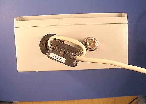
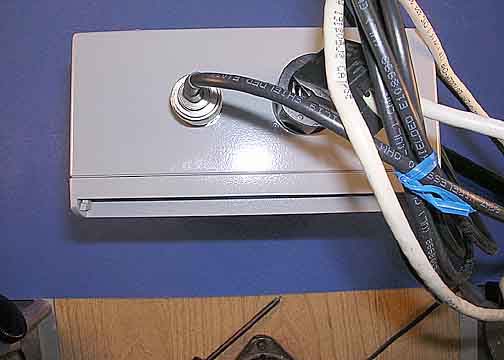
2407M Front 2407M Back 2407M Top 2407M Bottom 2407M Left 2407M Right

External Photos

24150 Front 24150 Back 24150 Top 24150 Bottom 24150 Left 24150 Right

External Photos

2419F Top 2419F Bottom 2419F Back 2419F Left 2419F Right

External Photos

2420S Front 2420S Back 2420S Top 2420S Bottom 2420S Left 2420S Right

Internal Photos

2407M Inside 2407M Main Board Top 2407M Main Board Bottom 2407M Wireless Card Top 2407M Wireless Card Bottom Case with Ground Plane G2407M Ground Plane Top 2407M Ground Plane Bottom Antenna

Internal Photos

2419F Back Shell 2419F Inside 2419F Main Board Top 2419F Main Board Bottom 2419F Transmitter Board Top 2419F Transmitter Board Bottom 2419F Ground Plane Top and Filter 2419F Ground Plane Bottom 2419F Antenna Front 2419F Antenna Back

Internal Photos

2420S Inside 2420S Main Board Top 2420S Main Board Bottom 2420S Transmitter Board Top 2420S Transmitter Board Bottom 2420S Sector Antenna Front 2420S Sector Antenna Back 2420S Ground Plane With Filter 2420S Filter on Ground Plane 2420S Ground Plane Bottom

Internal Photos

24150 Inside 24150 Main Board Top 24150 Main Board Bottom 24150 Transmitter Board Top 24150 Transmitter Board Bottom 24150 Ground Plane with Filter 24150 Filter on Ground Plane 24150 Ground Plane Bottom 24150 Antenna

RF Exposure Info

5046 Sierra Pines Dr.Mariposa, CA 95338 FCC 1.1310(b), Maximum Permissible Exposure Calculations Date of Report3/14/06 Calculations prepared for: Alico Systems Inc. 2461 W. 205th ST, STE B105 Torrance CA, 90501 Calculations prepared by: Eddie Wong 110 N. Olinda Place Brea, CA 9283 Model Number: WNE-2407M, WNE-5809M FCC Identification: NA Fundamental Operating Frequency: 2412- 2462 MHz, 5745 - 5825 MHz Maximum Rated Output Power: 0.7762W 2.8184W Measured Output Power: 0.7762W 2.8184W MPE Limit in accordance with 1.1310(b): Limits for general population/uncontrolled exposure MPE Limit for 2412- 2462 MHz = 1 mW/cm 2 (10 W/m 2 ) multiply mw/m by 10 MPE Limit for 5745 - 5825 MHz = 1 mW/cm 2 (10 W/m 2 ) multiply mw/m by 10 (B) Limits for General Population/Uncontrolled Exposure 0.3-1.34 614 1.63 *(100) 30 1.34-30 824/f 2.19/f *(180/f2) 30 30-300 27.5 0.073 0.2 30 300-1500 --- --- f/1500 30 1500-100,000 --- --- 1.0 30min Power Output (Watts) Power Density Limit (mW/cm 2 ) Minimum Distance (Meters) 2.4 GHz 1 0.0785 5.8 GHz 1 0.1657 P t = Power Delivered to the Antenna G = Antenna Gain d = Distance in meters Zo = Impedance of Free Space The typical antennas to be used with the EUT are structure mount antennas which under normal operation has at least 0.2 meter separation from a user. As can be seen from the MPE result, this device passes the limit specified in 1.1310 at a distance of 0.16 and 0.08 meter. Calculation: 2.4 GHz, 7 dBi Omni, 21.9 dBm ( conducted power) 21.9 dBm + 7 dB = 28.9 dBm = 0.7762 Watt = 0.0785 meter. 5.8 GHz, 9 dBi Omni, 25.5 dBm ( conducted power) 25.5 dBm + 9 dBi = 34.5 dBm = 2.8184Watt = 0.1657 meter. 377 x 10 1 7762.0 30xx d= 0 2 t 2 x Zd G x P x 30 )(W/m Density Power= 377 x 10 1 45.3 30xx d=

Test Report

Page 1 of 124 Report No: FC06-009A ADDENDUM TO ALICO SYSTEMS, INC. TEST REPORT FOR THE BROADBAND 802.11 B/G/A ACCESS POINT AND BRIDGE, 24-SB-07M, 24-LB-15O, 24-AE-19F AND 24-LB-20S FCC PART 15 SUBPART C SECTIONS 15.207 & 15.247 AND SUBPART B SECTIONS 15.107 & 15.109 CLASS A COMPLIANCE DATE OF ISSUE: AUGUST 9, 2006 PREPARED FOR: Alico Systems, Inc. 2461 W. 205th St., STE B105 Torrance, CA 90501 PREPARED BY: Mary Ellen Clayton CKC Laboratories, Inc. 5046 Sierra Pines Drive Mariposa, CA 95338 P.O. No.: W.O. No.: 15 84441 Date of test: January 18 - March 14, 2006 Report No.: FC06-009A This report contains a total of 124 pages and may be reproduced in full only. Partial reproduction may only be done with the written consent of CKC Laboratories, Inc. The results in this report apply only to the items tested, as identified herein. Page 2 of 124 Report No: FC06-009A TABLE OF CONTENTS Administrative Information .............................................................................................4 FCC to Canada Standard Correlation Matrix...................................................................5 Conditions for Compliance ..............................................................................................6 Approvals .........................................................................................................................6 FCC 15.33(a) Frequency Ranges Tested .........................................................................7 FCC 15.35 Analyzer Bandwidth Settings ........................................................................7 FCC 15.203 Antenna Requirements ................................................................................7 EUT Operating Frequency ...............................................................................................7 Equipment Under Test (EUT) Description ......................................................................8 Equipment Under Test .....................................................................................................8 Peripheral Devices ...........................................................................................................10 Report of Measurements ..................................................................................................11 Table 1: FCC 15.107 Six Highest Conducted Emission Levels ..........................11 Table 2: FCC 15.109 Six Highest Radiated Emission Levels .............................12 Table 3: FC 15.207 Six Highest Conducted Emission Levels.............................13 Table 4: FCC 15.247(d) Six Highest Radiated Emission Levels.........................14 FCC Part 15.247(b)(3) RF Power ........................................................................15 FCC Part 15.247(d) Bandedge .............................................................................28 Temperature And Humidity During Testing....................................................................36 EUT Setup........................................................................................................................36 Correction Factors............................................................................................................36 Table A: Sample Calculations .............................................................................36 Test Instrumentation and Analyzer Settings ....................................................................37 Spectrum Analyzer Detector Functions ...............................................................37 Peak..........................................................................................................37 Quasi-Peak ...............................................................................................37 Average ....................................................................................................37 EUT Testing.....................................................................................................................38 Mains Conducted Emissions................................................................................38 Antenna Conducted Emissions ............................................................................38 Radiated Emissions ..............................................................................................38 Appendix A: Test Setup Photographs..............................................................................39 Photograph Showing Mains Conducted Emissions .............................................40 Photograph Showing Mains Conducted Emissions .............................................41 Photograph Showing Mains Conducted Emissions .............................................42 Photograph Showing Mains Conducted Emissions .............................................43 Photograph Showing Mains Conducted Emissions .............................................44 Photograph Showing Mains Conducted Emissions .............................................45 Photograph Showing Radiated Emissions ...........................................................46 Photograph Showing Radiated Emissions ...........................................................47 Photograph Showing Radiated Emissions ...........................................................48 Photograph Showing Radiated Emissions ...........................................................49 Page 3 of 124 Report No: FC06-009A Photograph Showing Radiated Emissions ...........................................................50 Photograph Showing Radiated Emissions ...........................................................51 Photograph Showing Radiated Emissions ...........................................................52 Photograph Showing Radiated Emissions ...........................................................53 Photograph Showing Radiated Emissions ...........................................................54 Photograph S…

Text truncated - open the document above for the full version.

Test Report

FCC CFR47 PART 15 SUBPART C CERTIFICATION TEST REPORT FOR 2.4 GHz 802.11 b/g MINI PCI CARD MODEL NUMBER: SR2 FCC ID: SWX-SR2 REPORT NUMBER: 05U3280-1 ISSUE DATE: MAY 9, 2005 Prepared for UBIQUITI NETWORKS 1111 WEYBURN LANE, SUITE 41 SAN JOSE, CA 95129 U.S.A. Prepared by COMPLIANCE ENGINEERING SERVICES, INC. d.b.a. COMPLIANCE CERTIFICATION SERVICES 561F MONTEREY ROAD, MORGAN HILL, CA 95037, USA TEL: (408) 463-0885 FAX: (408) 463-0888 REPORT NO: 05U3280-1 DATE: MAY 9, 2005 EUT: 2.4 GHz 802.11 b/g MINI PCI CARD FCC ID: SWX-SR2 Page 2 of 90 COMPLIANCE CERTIFICATION SERVICES DOCUMENT NO: CCSUP4031A 561F MONTEREY ROAD, MORGAN HILL, CA 95037 USA TEL: (408) 463-0885 FAX: (408) 463-0888 This report shall not be reproduce…

Text truncated - open the document above for the full version.

Contact Information

Applicant

Syed Murtuza Akbar(President & CEO)
[email protected]562-436-1510Fax: 562-436-0039

Technical Contact

CKC Laboratories, Inc.Mary Ellen Clayton
[email protected]209-966-5240

5046 Sierra Pines Drive · Mariposa, California · United States

Non-Technical Contact

CKC Laboratories, Inc.Mary Ellen Clayton
[email protected]209-966-5240

Test Firm

CKC Laboratories, Inc.Steve Behm
[email protected]209-966-5240Fax: 866 779 9776

Technical Specifications

#Rule PartsFrequency RangePower Output
115C2.41 GHz - 2.46 GHz154.88 mW
Modular Type
Limited Single Modular Approval
Confidentiality
Long Term
Grant Notes
Limited Modular Approval (LMA). Power Output listed is Conducted. All final products require professional installation. Approval is valid only when installed in devices produced by the grantee. This device is approved for use in mobile and fixed operating conditions only. Approved for collocation with FCC ID: TVQ-U58A where the transmitters do not share the same antenna. The antennas used for this transmitter must be installed to provide a separation distance of at least 20 cm from all persons and must not be co-located or operating in conjunction with any other antenna or transmitter. Grantee must ensure that the end user has no manual instructions to remove or install the device. End-users and installers must be provided with antenna installation instructions and transmitter operating conditions for satisfying RF exposure compliance. Approved for use with antenna(s) as listed in this filing. Separate approval is required for all other operating configurations, including portable configurations with respect to 2.1093.

Other Applications from Alico Systems Incorporated

5.8 GHz Wireless Network Equipment - FCC ID TVQ-U58A - Alico Systems Incorporated
TVQ-U58A

5.8 GHz Wireless Network Equipment

Aug 10, 2006

Equipment Class

DTS - Digital Transmission System