TVYGIR2005NDU1.6/2.4 GHz Signal Booster (Indoor)
DACOM Corporation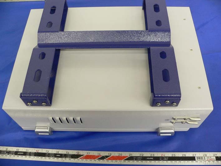
Click to zoom
Application Details
- Equipment Class
- TNB - Licensed Non-Broadcast Station Transmitter
- Date of Grant
- Jan 16, 2006
- Application Purpose
- Original Equipment
- Date of Application
- Jan 16, 2006
- Equipment Note
- 1.6/2.4 GHz Signal Booster (Indoor)
- Frequency Range
- 2485.50000000 - 2498.50000000
- Company
- DACOM Corporation
- Country
- South Korea
Documents & Files
Document Text
Text extracted from the exhibit documents filed with the FCC. Open a document above to read the original.
Users Manual
GIR-2005 User Manual 1 All Rights Reserved Installation & Operation Manual For the GIR - 2005 Oct. 2005 DACOM GIR-2005 User Manual 2 All Rights Reserved ==== Table of Contents ==== I. GIR-2005 Overview 1. GIR-2005 Service Network 2. GIR-2005 Overview 3. GIR-2005 Configuration II. Preparation to install the GIR-2005 1. Safety 2. Environment 3. GIR-2005 Dimensions III. GIR-2005 Installation 1. IDU (Indoor Unit) Installation 2. ODU (Outdoor Unit) Installation 3. Interconnection between IDU and ODU 4. Parameter Setting IV. GIR-2005 Basic Operation 1. Control Panel overview 2. Operating Considerations 3. Menu Configuration & Operation ※ Quick Start Reference Guide Appendix i. Components of GIR-2005 Appendix ii. Specifications of the GIR-2005 GIR-2005 User Manual 3 All Rights Reserved I. GIR-2005 Overview Globalstar using the LEO-satellites provides high quality communication services. But, the services are not available in the NLOS (Non Line-Of-Sight) environments such as indoors, tunnel and etc. GIR-2005 (Globalstar Indoor Repeater) can assist to provide the seamless Globalstar Services in the NLOS environments. 1. GIR-2005 Service Network At the indoor environment where the LOS environment is not constructed between the satellite and the terminal, we can provide the Globalstar Service to the terminal that is located on the indoor by connecting the outdoor unit and external antenna for the link with the satellite, indoor unit and indoor Tx/Rx patch antennas for the link with the terminal. 2. GIR-2005 Overview Place the GIR-2005 ODU (Outdoor Unit) and the external antenna on the building roof, and put IDU (Indoor Unit) and its patch antennas inside the building. These two units receive, amplify, and retransmit each downlink signal of the satellite and uplink signal of the terminal to expanded signal arrival area. Thus the service is possible in the interior. Unlike a general ground mobile communication repeater, signal level of GIR-2005 received from the satellite is feeble differently and the fluctuation over time varies hourly. Therefore a high gain amplifier is necessary, but the possibility of oscillation may increase due to the high gain amplifier. To prevent the oscillation, the isolation between ODU and IDU antenna must be over 80dB. 3. GIR-2005 Configuration GIR-2005 Repeater is composed with one Indoor Unit, one Outdoor Unit and Indoor Antenna Set(Tx/Rx Patch antennas). GIR-2005 User Manual 4 All Rights Reserved ※ External antenna do not comes with the package. Should purchase separately. Figure 1-1 Block diagram of the GIR - 2005 II. Preparation to install the GIR-2005 1. Safety 1. 1. Before you begin, refer to the local Safety standard for the power source, grounding, and other safety information. GIR-2005 User Manual 5 All Rights Reserved 2. Environment 2. 1. Verify if you have a correct operating environment. 2. 2. The instrument operates properly in ambient temperatures from -20°C to +50°C and relative humidity from 5% to 95%. 3. GIR-2005 Dimensions 3. 1. Indoor Unit The following Figure 2-1 shows the dimensions of the Indoor Unit. Figure 2-1 Dimensions of the Indoor Unit GIR - 2005 GIR-2005 User Manual 6 All Rights Reserved 3. 2. Outdoor Unit Refer to the Figure 2-2 for the dimensions of the Outdoor Unit. Figure 2-2 Dimensions of the Outdoor Unit GIR - 2005 ANT(RX)ANT(TX)TO IDU GIR-2005 User Manual 7 All Rights Reserved III. GIR-2005 Installation First turn off the power, and install IDU inside of building, and ODU outside of building where has clear visibility with no obstacle facing. “On top of the roof” is recommended place to put. After installing IDU and ODU, connect IDU and ODU with appropriate cable. Then turn on the power. Using control panel of IDU, set up the parameters of IDU & ODU to work properly. While doing this procedure, must take a note below for considerations of installation. To avoid oscillation, the indoor and outdoor antenna must be get 80dB of minimum Isolation. For the installation place of the repeater in indoors, secure the visibility range as possible, and separate from the outdoor antenna as far as possible. Follow the instruction below to install IDU & ODU to the appropriate place. 1. IDU (Indoor Unit) Installation IDU can be placed on the supporting structure like a desk or installed on the interior wall. If choose to install on the wall, fallow instruction below. Then connect cables from each of TX, RX patch antennas to IDU as described in this manual. Please note that all the procedure must take while power is off. 1.1 Fixing At first, using the M12 Anchor bolts, install GIR-2005 Chassis bracket into the wall Bracket that is fixed to the wall in Figure 3-1. And then, using M4 bolt, assemble GIR- 2005 with Chassis bracket and wall-bracket. GIR-2005 User Manual 8 All Rights Reserved Fig. 3-1 Assemble Wall Bracket with GIR-2005 Chassis Bracket 1.2 Grounding After GIR-2005 Indoor Unit is fixed to the wall, using 14 Square Cable put the ground post of GIR-2005 chassis to the earth where has good conductivity. Refer to the figure below. Fig. 3-2 GIR-2005 Grounding 4×(3×M4 Bolt) 4×M12 Anchor Bolt GIR-2005 User Manual 9 All Rights Reserved 1.3 Connecting Internal antenna with cables Place GIR – 2005 indoor antenna close to the ceiling and far from the window of inside the building. Antenna direction is recommended to face to wall side not to window side to minimize coupling between Indoor and outdoor antenna. Install the each of indoor patch antennas at the right and left side of the Indoor Unit. Do not exceed 3 meter for the distance between IDU and indoor patch antenna each. Connect TX/RX cables from antenna to IDU. 2. ODU (Outdoor Unit) Installation Place ODU outside of building with no visible obstacle in front of ODU. Follow the instruction below to install ODU on the proper place, install external antenna, and connect cables between antenna and ODU as well. Refer to the figure 3-3 below. Fig. 3-3 GIR-2005 ODU Installation GIR-2005 User Manual …
Text truncated - open the document above for the full version.
Block Diagram
Down Converter DownLink IF Duplexer U p Conve rte r UpLink HPA Power Detector MPU/ PLL/ Power Detect/ HPA CTRL On/Off CTRL FSK Transceiver ODU Monit or/C ont rol Data DC/DC Converter Signal Combiner ALC IF Duplexer Up Converter HPA Down Link Pow er Detector Up Link Signal Combiner Coax CABLE (Up/Down Link IF, DC & Control RF) DC/DC Converter D C F eeding FSK Transceiv er MP U ODU Monitor/C ont rol Data Down Converter Digital Control At tenuator ALC Up Link Power Detector (ODU HPA On/Off) Local Synthesizer Local Synthesizer Digit al Attenuator
External Photos
DACOM Corporation FCC ID: TVYGIR2005NDU Report # R0511224Exhibits (Indoor unit) FCC Part 25 Test Report EXHIBIT C - EUT PHOTOGRAPHS EUT-Front View EUT-Bottom View DACOM Corporation FCC ID: TVYGIR2005NDU Report # R0511224Exhibits (Indoor unit) FCC Part 25 Test Report EUT- Port View (1) EUT- Port View (2)
ID Label/Location Info
EXHIBIT A - FCC ID LABEL INFORMATION Proposed FCC ID Label Proposed Label Location on EUT Rear Side of the EUT / Label Location FCC ID: TVYGIR2005NDU
Internal Photos
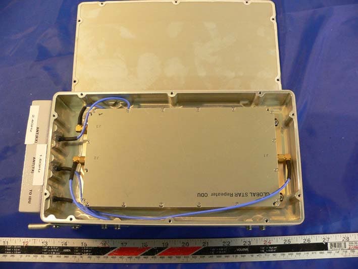
DACOM Corporation FCC ID: TVYGIR2005NDU Report # R0511224Exhibits (Indoor unit) FCC Part 25 Test Report EUT- Cover off View EUT-Repeater View DACOM Corporation FCC ID: TVYGIR2005NDU Report # R0511224Exhibits (Indoor unit) FCC Part 25 Test Report EUT-Repeater Cover off View EUT-Repeater Close View DACOM Corporation FCC ID: TVYGIR2005NDU Report # R0511224Exhibits (Indoor unit) FCC Part 25 Test Report EUT- Keypad Unit View EUT- Keypad Unit Port View DACOM Corporation FCC ID: TVYGIR2005NDU Report # R0511224Exhibits (Indoor unit) FCC Part 25 Test Report EUT- Keypad Unit Cover off View EUT- Keypad Unit LCD View DACOM Corporation FCC ID: TVYGIR2005NDU Report # R0511224Exhibits (Indoor unit) FCC Part 25 Test Report EUT- Keypad Unit Component View EUT- Keypad Unit Main board Component View DACOM Corporation FCC ID: TVYGIR2005NDU Report # R0511224Exhibits (Indoor unit) FCC Part 25 Test Report EUT- Keypad Unit Main board Solder View EUT- Power Supply View DACOM Corporation FCC ID: TVYGIR2005NDU Report # R0511224Exhibits (Indoor unit) FCC Part 25 Test Report Power Supply Connector View Power Supply Cover off View DACOM Corporation FCC ID: TVYGIR2005NDU Report # R0511224Exhibits (Indoor unit) FCC Part 25 Test Report Power Supply board Component View Power Supply board Solder View DACOM Corporation FCC ID: TVYGIR2005NDU Report # R0511224Exhibits (Indoor unit) FCC Part 25 Test Report Indoor Antenna Front View Indoor Antenna Rear View
Operational Description
Circuit Description “GIR-2005” is consists of the IDU (indoor unit) and ODU (outdoor unit), and each units is installed at indoor and outdoor. 2.4GHz signal from a satellite comes in receiving antenna of the ODU and the signal comes in the inside of ODU after amplified by LNA. The inside of the ODU has a Down Converter, so the signal frequency is changed to 240MHz. At this time, amplify of the signal is carried out also. Using ALC and Digital Attenuator, the signal level is controlled and the signal is changed as a satellite signal frequency by Up Converter. This signal is emitted by indoor antenna and if the terminal receives the proper signal, the terminal carries out a certification process. Upper system is a downward (Rx) signal and Rx signal always maintains On state. When the terminal receives Rx signal and carries out a certification process, the terminal transmit a RF upward (Tx) signal. At this time, frequency is a 1.6GHz This signal is changed to 140MHz by Down Converter of the IDU ’ s first block and the signal is detected by Power Detector of the IDU ’ s second block. If the signal is detected by Power Detector, the IDU commands ‘HPA On’ to the ODU by FSK Transceiver. Because the Block, before HPA block of the ODU, has a Digital Attenuator and an ALC, the Tx power can be controlled. Only one cable exists between the IDU and the ODU. Using this cable, Tx RF signal, Rx RF signal, FSK signal (role of communication between the IDU and the ODU), power supply (from the IDU to the ODU) are carried out. Inside of the IDU has a Control Panel. Control and monitoring of the transmission signal strength, HPA Mode control (On, Off, Auto), HPA Off Delay (waiting time to turn it off of HPA when the signal disappears), Fan control and temperature monitoring are carried out using this Control Panel. The signal from a satellite and the transmission signal of the IDU use the same frequency. If this signal goes into input part of the ODU, it may cause a spurious. Also, the transmission signal from the terminal and the transmission signal from the ODU to a satellite use the same frequency. If the transmission signal of the ODU goes into input part of the IDU, it may cause a spurious too. So, the isolation, between the ODU and the IDU, must be more than 80dB at least and more than 100dB for steady operation. With reference, FSK Transceiver frequency is a 433MHz.
Parts List/Tune Up Info
IDU (Indoor Unit) Tune up procedure Installation IDU can be placed on the supporting structure like a desk or installed on the interior wall. If choose to install on the wall, fallow instruction below. Then connect cables from each of TX, RX patch antennas to IDU as described in this manual. Please note that all the procedure must take while power is off. 1.1 Fixing At first, using the M12 Anchor bolts, install GIR-2005 Chassis bracket into the wall Bracket that is fixed to the wall in Figure 3-1. And then, using M4 bolt, assemble GIR-2005 with Chassis bracket and wall-bracket. Fig. 3-1 Assemble Wall Bracket with GIR-2005 Chassis Bracket 4×(3×M4 Bolt) 4×M12 Anchor Bolt 1.2 Grounding After GIR-2005 Indoor Unit is fixed to the wall, using 14 Square Cable put the ground post of GIR-2005 chassis to the earth where has good conductivity. Refer to the figure below. Fig. 3-2 GIR-2005 Grounding 1.3 Connecting Internal antenna with cables Place GIR – 2005 indoor antenna close to the ceiling and far from the window of inside the building. Antenna direction is recommended to face to wall side not to window side to minimize coupling between Indoor and outdoor antenna. Install the each of indoor patch antennas at the right and left side of the Indoor Unit. Do not exceed 3 meter for the distance between IDU and indoor patch antenna each. Connect TX/RX cables from antenna to IDU. . ODU (Outdoor Unit) Tune up procedure Installation Place ODU outside of building with no visible obstacle in front of ODU. Follow the instruction below to install ODU on the proper place, install external antenna, and connect cables between antenna and ODU as well. Refer to the figure 3-3 below. Fig. 3-3 GIR-2005 ODU Installation 2.1 Fixing Outdoor Unit either can be installed to the wall or mast Pipe. If you select a wall to fix, do same as what you did with Indoor Unit. If you select a mast pipe to fix, first find the solid structure and fix the 20~30mm diameter pipe to it, and assemble ODU to the pipe using a wall and pipe bracket. Fig 3-4 Outdoor Unit Fixing to the wall 2.2 Grounding After GIR-2005 Outdoor Unit is fixed, should ground it using 14 Square Cable connected to the grounding post of GIR-2005 chassis and earth where has good connectivity. 2.3 Connecting Internal antenna with cables Connect cables with TX/RX making to relevant place of ODU using specified cables like figure from each of TX RX patch antennas to IDU like figure 3-5. Please note that all the procedure must take while power is off. 4×(2×M4 Bolt) 4×M7 Anchor Bolt
RF Exposure Info
§1.1307(b)(1) & §2.1091 - RF EXPOSURE According to §1.1307(b)(1), systems operating under the provisions of this section shall be operated in a manner that ensures that the public is not exposed to radio frequency energy level in excess of the Commission’s guidelines. According to §1.1310 and §2.1091 RF exposure is calculated. Limits for General Population/Uncontrolled Exposure Frequency Range (MHz) Electric Field Strength (V/m) Magnetic Field Strength (A/m) Power Density (mW/cm 2 ) Averaging Time (minute) Limits for General Population/Uncontrolled Exposure 0.3-1.34 614 1.63 *(100) 30 1.34-30 824/f 2.19/f *(180/f 2 ) 30 30-300 27.5 0.073 0.2 30 300-1500 / / f/1500 30 1500-100,000 / / 1.0 30 f = frequency in MHz * = Plane-wave equivalent power density MPE Prediction Predication of MPE limit at a given distance Equation from page 18 of OET Bulletin 65, Edition 97-01 S = PG/4πR² Where: S = power density P = power input to antenna G = power gain of the antenna in the direction of interest relative to an isotropic radiator R = distance to the center of radiation of the antenna Maximum peak output power at antenna input terminal: 10.08(dBm ) Maximum peak output power at antenna input terminal: 10.2 (mW) Predication frequency: 2500 (MHz) Antenna Gain (typical): 4(dBi) Antenna gain: 2.5 (numeric) Power Density at Prediction Distance: 1 (mW/cm 2 ) Predication Distance: 20 cm MPE limit for uncontrolled exposure at prediction frequency: 1.0 (mW/cm 2 ) Test Result The EUT is a mobile device. The predication distance is 20 cm.
Schematics
Version 1.4 Global Star Repeater Approved Designed Manager Director President AGND DOC. NUMBER SHEET 1 OF 12 DRWNDATE 05 09 08 05 06 21 UPDATE 05 09 08 CKDAPPDAPPD DATE V1.0 MODIFY REV. GS Repeater (IDU UpLink) DOC. NAME 100pF C143 C351nF AGND C1451nF +5VDC +9VDC AGND 10nFC82 R31300 AGND 4.7 R63 +5VDC +5VDC +9V VDD C73 1nF 1nFC142 +5VDC 1KR65 2 GND2GND3 34 GND4GND5 56 GND6GND7 7 GND8 8 9 GND9 U18 HMC308 2 GND1 GND3 56 GND4 4 IN OUT 13 C76 1nF U82 DPX240_140MS20A 10 140 240 16 GND1 1 GND10 1112 GND11ANT 1314 GND13GND14 15 GND15 17 18 GND16 +5VDC AGND AGND AGND AGND 1.2 R64 AGND 100R59 SMA_PAD P2 1 R60100 +5VDC 24nHL6 1nF C34 AGND R61 150 100pFC112 HMC308 U19 GND1 2 5 GND3GND4 6 IN 4 1 OUTVDD 3 AGND AGND AGNDAGND AGND 10pF C80 51 R62 AGND C111100pF 100pFC146 1nF C71 18 U37 HMC315 2 GND1 GND2 4 GND3 5 6 GND4 3 IN OUT 1 AGND C77 1nF 100pF C72 L17100nH R29 C68 C79 470pF AGND 100pF C78 1 NC1 NC10 9 14 NC11 12 NC2 6 NC3 16 NC4 3 NC5 NC6 7 10 NC7 4 NC8 8 NC9 RFIN 2 RFOUT 11 VDD1 15 VDD2 13 470pF AGND 100 R78 AGND U16 HMC375LP3 ACG 5 BASE 17 L5 33nH AGND C147 1nF C144 1nF GND13 GND14 143 GND2 GND3 4 5 GND4 GND5 6 7 GND6 GND8 8 IN 1 OUT 9 1nF C75 AGND +5VDC 100nHL16 BPF46R1618S20A U17 2 GND1 10 GND10 GND11 11 GND12 12 13 L15100nH 100pF C70 C69 1nF OUT +5VDC U34 BPF140MS02A 2 GND1 5 GND2 GND3 3 GND4 4 1 IN 6 OUT AGND C83 1nF JSPHS_150 U36 BIAS1 1 BIAS2 7 2 GND1GND10 13 GND2 3 4 GND3 GND4 5 6 GND5GND6 9 10 GND7 GND8 11 12 GND9 14 IN 8 AGND 10K VR3 1 2 3 AGND 12nH L4 GND5 6 7 GND6 GND8 8 IN 1 OUT 9 AGND HMC315 U35 GND1 2 4 GND2 5 GND3 GND4 6 IN 3 1 OUT AGND AGND BPF46R1618S20A U15 2 GND1 10 GND10 GND11 11 GND12 12 13 GND13 GND14 143 GND2 GND3 4 5 GND4 5 6 GND4 3 IN OUT 1 AGNDAGND VR2 10K 1 2 3 1nF C33 IN2* 6 1 OUT1 7 OUT2 C74 100pF AGND AGND U33 HMC315 2 GND1 GND2 4 GND3 C81 8.2pF 220nH L18 AD8052ARM U39 +VS 8 -VS 43 IN1 IN1* 2 5 IN2 AGND AD8310ARM U38 BFIN 6 COMM 27 ENBL INHI 8 1 INLO 3 OFLTVOUT 45 VPOS AGND 2 LO NC 4 RF 7 AGND AGND +5VDC C141 100pF L55 SLF6028 P3 SMA_PAD 1 C36 100pF HMC207S8 U20 GND1 1 GND2 36 GND3 8 GND4 IF 5 CTRL_RF_IDU IDU_UL_ON IDU_IF IDU_DL_IF 300R30 IDU_UL_IN IDU_UL_LO P_CTRL NAME DOC. L118nH NUMBER SHEET 2 OF 12 DRWNDATE 05 06 21 UPDATE 05 09 08 CKDAPPDAPPD DATEREV. GS Repeater (IDU DownLink ) V1.0 MODIFY 05 09 08 DOC. 330pF C1 C91 330pF C94100pF 200R1 +5VDC 68nH L10 R9200 C53 51 R10 AGND C2 330pF 270pF C99 C40 470pF 1nF C51 1nF 1nF C101 100nHL7 +5VDC RF2V1 5 4 V2 V3 3 2 V4 V5 1 C47 1nF 7pF C45 AGND L9 82nH U4 HMC273MS10G GND1 9 8 GND2 GND3 7 11 PXG_GND 10 RF1 6 R75 43K R6 1K 1nFC125 3.3nH L2 DECL 9 6 DETO 2 ENBLEGAIN 5 HPFL 13 ICOM1 1 ICOM2 7 14 ICOM3 INPT 34 MODE 8 OCOM1 10 VOUT 12 VPSI VPSO 11 12K U26 AD8052ARM 8 +VS 4 -VSIN1 32 IN1* IN2 56 IN2* OUT1 1 OUT2 7 AD8367ARU U23 AGND LM78M05CDT U7 4 GND2 IN 1 3 OUT AGND +9VDC AGND R40 3 U21 HMC315 GND1 2 4 GND2 5 GND3 GND4 6 IN 3 1 OUT 1nFC122 R2 510 GND3 5 6 GND4 3 IN OUT 1 +5VDC R12 1K U2 KSE3_7TP1 2 GND IN 1 OUT 5.1KR3 R43 1K U24 HMC315 2 GND1 GND2 4 1610 ACOM2 2 CHPFCOMM 18 COMM2 CUPF 9 6 DECLINLO 54 INRIOECL 3 PWDN 7 12 VOUT VPOS 1315 VREF VSET 1114 VTGT +5VDC AGND +5VDC +5VDC 1nFC49 AGND AGND AD8362ARU U6 ACOM C12610nF AGND C96100pF C11 1nF AGND AGND 1K R5 C98100pF 18 R32 300R33 C41 10pF 100pF 100nHL11 R383K C12010nF C7 1nF C121 100pF 3KR39 C100 U22 BPF240MS02A 2 GND1 5 GND2 GND3 3 GND4 4 1 IN 6 OUT 3pF C50 1nF C9 100pF C5 100 R11 1 AGND C43 3.3nF AGND VR1 10K 1 2 3 82K R42 HMC308 U8 GND1 2 5 GND3GND4 6 IN 4 1 OUTVDD 3 P1 SMA_PAD R76 1nFC119 C46100nF AGND 1nFC90 L8 220nH +5VDC 10K AGND AGND U25 AD8310ARM 6 BFIN 2 COMM ENBL 78 INHI INLO 1 OFLT 34 VOUT VPOS 5 2.7pF C3 AGND 470pF C37 C92100pF 100pFC97 5 IN 1 2 NC OUT1 3 4 OUT2 9 PXG_GND VCC 7 8 VPD1 6 VPD2 AGND AGND R34300 C52 100pF L3 5.6nH +5VDC U1 HMC414MS8G GND 3 VDD 20pFC44 AGND C8 1.5pF AGND AGND AGND 200 R35 AGND U3 HMC308 2 GND1 GND3 56 GND4 4 IN OUT 1 GND11 12 GND12 GND13 13 14 GND14GND2 3 4 GND3 GND4 5 6 GND5 GND6 7 8 GND8 1 IN 9 OUT R4 1K R44 10K AGND 100pF C10 U9 BPF46R2492S20A GND1 2 GND10 10 11 150K R41 C1271nF AGND 1K R7 AGND AGND AGND +5VDC AGND AGND AGND 100pF R36 51 AGND 1nF C38 AGND AGND +5VDC AGND AGND AGND 1.5pFC6 C39 10 GND10 GND11 11 GND12 12 13 GND13 GND14 143 GND2 GND3 4 5 GND4 GND5 6 7 GND6 GND8 8 IN 1 OUT 9 AGND +5VDC 10nFC48 +5VDC 100pFC93 BPF46R2492S20A U5 2 GND1 R8 1K R37 4.7 100pFC95 C42.2uF U10 HMC332 2 GND1 5 GND2 3 IF LO 64 RF 1 VDD 8.2pF C42 IDU_DL_OUT IDU_TSSI IDU_DL_AT_1DBIDU_DL_AT_2DBIDU_DL_AT_4DBIDU_DL_AT_8DB IDU_DL_AT_16DB IDU_DL_IF IDU_DL_LO SHEET 3 NUMBER APPDAPPD DATEREV. GS Repeater (IDU Local Synthesizer) V1.0 MODIFY 05 09 08 NAME R70 R14 18 AGND DOC. DOC. OF 12 DRWNDATE 05 06 21 UPDATE 05 09 08 CKD C30 R45 680 2uF C32 1K 18 R22 AGND AGND 100pF C25 2.7nF 100pFC29 +5VDC C109 100pF 47uF,6V TC4 100 R17 R24 100 AGND R23 51 C110 10nF 270pFC24 AGND 100pF C16 AGND AGND AGND R1318 10 RFOUT VCC 14 VT 2 AGND R16 10K C17 270pF U14 KSV_5V1505 GND 5 1 GND1 13 GND10 15 GND11 GND12 16 3 GND2 4 GND3 6 GND4 GND5 7 8 GND6 GND7 9 GND8 1112 GND9 VCCIF VCCRF 2 VPIF 22 VPRF 3 TC3 47uF,6V 51 R15 AGND 1918 FINIF* 6 FINRFFINRF* 7 FO_LD 11 GND1 5 GND2 20 8 GND3 GND4 17 IF_EN 1316 LE 10 OSCINOSCX 91 OUT0 OUT1 24 RF_EN 12 23 R6951 AGND LMX2350TM U12 14 CLOCK 21 CPOIF CPORF 4 DATA 15 FINIF R26 1K R68 100pF C18 AGND C28 51pF AGND R2018 51 AGND AGND C105100pF 100pF C108 TC2 47uF,6V 270pFC22 C21 2uF 330 R46 1K R71 10nF C106 100pF AGND AGND C31 82nF +5VDC 270pF C27 AGND C26 RFOUT 10 14 VCC 2 VT AGND +5VDC +5VDC 100pF C104C103 100pF KSV_5V2220 U13 5 GND GND1 1 GND10 13 GND11 15 16 GND12 GND2 3 GND3 4 GND4 6 7 GND5 GND6 8 9 GND7 11 GND8GND9 12 OSCIN 10 9 OSCXOUT0 124 OUT1 12 RF_EN VCCIF 23 2 VCCRF 22 VPIF 3 VPRF 680 R27 AGND CLOCK 14 CPOIF 21 4 CPORF 15 DATA 19 FINIF FINIF* 18 FINRF 67 FINRF* 11 FO_LD 5 GND1 20 GND2 GND3 817 GND4 13 IF_EN LE 16 C14270pF C12270pF U11 LMX2350TM R67 1K C23270pF R72 1K Y1 TXO220UE-5 2 GNDNC 1 3 OUT 4 VCC 82nF C20 R66 1K 270pFC13 18R18 C19 2.7nF R25 C102 270pF R28 330 AGND C15 100pF AGND AGND 18R21 10K AGND +5VDC R19 18 270pF C107 PLL_I…
Text truncated - open the document above for the full version.
Test Report
Note: The test report is specially limited to the use of the above client company and this particular sample only. It may not be duplicated without prior written consent of Bay Area Compliance Laboratory Corporation. This report must not be used by the client to claim product certification, approval, or endorsement by NVLAP, NIST or any agency of the U.S. Government. FCC PART 25 TYPE APPROVAL EMI MEASUREMENT AND TEST REPORT For DACOM Corporation DACOM B/D, 65-228, Hangangro-3ga, Yongsan-gu, Seoul, Korea, 140-716 FCC ID: TVYGIR2005NDU This Report Concerns: Original Report Equipment Type: 1.6/2.4 GHz SIGNAL BOOSTER (Indoor unit) Test Engineer: Snell Leong Report No.: R0511224 Report Date: 2005-12-21 Reviewed By: Richard Lee Prepared By: Bay Area Compliance Laboratory Corporation (BACL) 230 Commercial Street Sunnyvale, CA 94085 Tel: (408) 732-9162 Fax: (408) 732 9164 DACOM Corporation FCC ID: TVYGIR2005NDU Report # R0511224Rpt (Indoor unit)-b.doc Page 2 of 41 FCC Part 25 Test Report TABLE OF CONTENTS GENERAL INFORMATION.......................................................................................................................................4 PRODUCT DESCRIPTION FOR EQUIPMENT UNDER TEST (EUT) ....................................................................................4 OBJECTIVE...................................................................................................................................................................4 RELATED SUBMITTAL(S)/GRANT(S).............................................................................................................................4 TEST METHODOLOGY..................................................................................................................................................4 TEST FACILITY.............................................................................................................................................................4 SYSTEM TEST CONFIGURATION ..........................................................................................................................6 JUSTIFICATION.............................................................................................................................................................6 EUT EXERCISE SOFTWARE..........................................................................................................................................6 SPECIAL ACCESSORIES.................................................................................................................................................6 SCHEMATICS / BLOCK DIAGRAM..................................................................................................................................6 EQUIPMENT MODIFICATIONS.......................................................................................................................................6 LOCAL SUPPORT EQUIPMENT LIST AND DETAILS........................................................................................................6 EXTERNAL I/O CABLING LIST AND DETAILS................................................................................................................6 CONFIGURATION OF TEST SYSTEM..............................................................................................................................7 TEST SETUP BLOCK DIAGRAM.....................................................................................................................................7 SUMMARY OF TEST RESULTS ...............................................................................................................................8 §2.1047 – MODULATION CHARACTERISTICS ....................................................................................................9 §2.1051 – SPURIOUS EMISSIONS AT ANTENNA TERMINALS .......................................................................10 STANDARD APPLICABLE............................................................................................................................................10 MEASUREMENT PROCEDURE......................................................................................................................................10 EQUIPMENT LISTS......................................................................................................................................................10 MEASUREMENT RESULT............................................................................................................................................10 §15.107 - CONDUCTED EMISSIONS ......................................................................................................................23 MEASUREMENT UNCERTAINTY..................................................................................................................................23 EUT SETUP................................................................................................................................................................23 RECEIVER SETUP........................................................................................................................................................23 TEST EQUIPMENT LIST AND DETAILS.........................................................................................................................23 TEST PROCEDURE......................................................................................................................................................23 TEST RESULTS SUMMARY..........................................................................................................................................24 CONDUCTED EMISSIONS TEST DATA.........................................................................................................................24 PLOTS OF CONDUCTED EMISSION.........................................................................…
Text truncated - open the document above for the full version.
Test Setup Photos
DACOM Corporation FCC ID: TVYGIR2005NDU Report # R0511224Exhibits (Indoor unit) FCC Part 25 Test Report EXHIBIT B - TEST SETUP PHOTOGRAPHS Conducted Emission-Front View Conducted Emission-Side View DACOM Corporation FCC ID: TVYGIR2005NDU Report # R0511224Exhibits (Indoor unit) FCC Part 25 Test Report Radiated Emission-Front View Radiated Emission-Rear View
Contact Information
Applicant
Jin-Wook Song(Director)
Test Firm
Bay Area Compliance LaboratoryJohn Chan
Technical Specifications
| # | Rule Parts | Frequency Range | Power Output | Emission | Tolerance |
|---|---|---|---|---|---|
| 1 | 25 | 2.49 GHz - 2.50 GHz | 10.00 mW | F9W | 0.0010000000 % |
Other Applications from DACOM Corporation
TVYGIR2005ODU
Jan 16, 20061.6/2.4 GHz Signal Booster (Outdoor)
Equipment Class
TNB - Licensed Non-Broadcast Station Transmitter