TWR-866-HYDRA-RMRemote Control
Hydra-ReMote, Inc.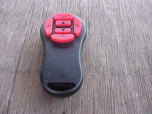
Click to zoom
Application Details
- Equipment Class
- DSC - Part 15 Security/Remote Control Transmitter
- Date of Grant
- Oct 16, 2006
- Application Purpose
- Original Equipment
- Date of Application
- Oct 16, 2006
- Equipment Note
- Remote Control
- Frequency Range
- 433.92000000 - 433.92000000
- Company
- Hydra-ReMote, Inc.
- Country
- United States
Documents & Files
Document Text
Text extracted from the exhibit documents filed with the FCC. Open a document above to read the original.
Users Manual
ORDERING NEW REMOTES If an additional remote is needed, it can be ordered by calling Hydra-ReMote Inc @ 1-866-HydraRM (1-866-493-7276) TROUBLESHOOTING Here are a few troubleshooting hints in the event of problem: Plow will not operate: 1) Check to make sure power is turned on. The LED should be green in color. 2) Make sure the plow wiring harness and receiver power cord connectors are completely seated. 3) Try the second transmitter (remote) to determine if it is a transmitter malfunction. 4) If a hard-wired handheld unit is available, try it to determine if the problem is in the plow wiring harness or plow. 5) Make sure the serial number on the receiver and the transmitter (remote) match. The serial number is located on the back side of remote and receiver box. Intermittent plow functions: 1) Make sure there are no obstructions between the antenna (power cable) and the remote. 2) Slightly move the receiver left, right, up or down slightly (one or two inches). RF devices will experience some areas of minimal radio reception. 3) Make sure cellular phones or other two way radios are not in operation and in close proximity of the antenna. WARRANTY The Hydra-V wireless controller’s two year limited warranty covers any failure due to manufacturer’s material or workmanship. The warranty period begins on the date of consumer purchase. Please contact Hydra-ReMote Inc. to obtain a return authorization prior to returning the unit. Hydra-ReMote Inc. 412 S Chicago Street P.O. Box 576 Royal Center, IN 46978 www.hydraremote.com Phone: (574) 643-6500 or (866) HydraRM HYDRA-V WIRELESS SNOW PLOW REMOTE CONTROL Congratulations on your purchase of a Hydra-V Wireless remote control for your snowplow. INSTALLATION This device is extremely simple to install and operate. Installation should be accomplished without any special tools. 1) Make sure the toggle switch on the top of the receiver is down (OFF position). 2) Turn off all power to the plow. Most plow installations use ignition, but some are directly wired to battery. 3) Choose a location (usually on the driver’s kick panel) where the receiver cord will plug into the existing snow plow connection. The receiver uses the power cable as the antenna, so a location should be chosen to provide a line of sight between the cable and wireless remote. This is to minimize “dead” spots, which may occur during the plow operation. Position the wire away from any cellular phones, two-way radios, etc. as this is a RF device and performance can be affected by close proximately to such devices. 4) Apply the Velcro provided on the location chosen and then apply the mating Velcro to the backside of the controller (non-label side). 5) Plug the controller into the existing snow plow connector. 6) Apply power to the plow. 7) Flip the toggle switch on the unit up to the ON position and check to see if the LED illuminates green. 8) If not, check that the snow plow is powered and ready to be operated with a control. 9) If the snow plow does not function, refer to the troubleshooting section for additional information. OPERATING THE REMOTE Operation of the wireless remote is extremely simple and with a short amount of use it will become completely second nature to most operators. The controller is designed with ease of operation in mind. This is shown in the simple six button/ten function control. NEVER attempt operation outside of vehicle with this remote. It is designed for limited range and will not reliably operate outside of the vehicle. Pressing SCOOP button A will bring the plow into a scoop position by automatically positioning both wings forward. Pressing VEE will bring the plow into a V position by automatically releasing both wings to return to their rest position. Pressing LEFT will bring the plow into a left angle position by automatically positioning the right wing forward and returning the left wing to it’s rest position. Pressing RIGHT will bring the plow into a right angle position by automatically positioning the left wing forward and returning the right wing to it’s rest position. Pressing UP will raise the plow. Pressing DOWN will lower the plow. By holding the button for 1 second or more the plow will go into the “float” mode. The receiver’s green power LED will turn RED during float condition. Float will operate with all other plow functions and will not be disabled until the lift UP is pressed. When raising the plow a few other button functions are allowed to be operated simultaneously. Scoop, Right Angle, and Left Angle are all functions allowed to operate with the UP button. As a safety feature, the DOWN button is a dedicated button. No other function is allowed to operate with DOWN. Independent wing operation is accomplished by pushing the corners of the four large function buttons. Pressing SCOOP with LEFT will extend the left wing forward. Pressing SCOOP with RIGHT will extend the right wing forward. Pressing VEE with LEFT will retract the left wing to retract. Pressing VEE with RIGHT will retract the right wing. These functions are the four least used functions of the ten. Consequently they require dual button pushes. Upon transporting plow ALWAYS shut off the toggle switch at the top of the receiver. CHANGING OF TRANSMIT CODES In some instances multiple Hydra-V remotes may be operating in the same general area. If this occurs, there are 256 different codes available for each controller. To change the code, disconnect the power cable from the snow plow wiring harness. Remove the four screws on the receiver box. Set the eight dip switches to a different code. Open the transmitter remote by removing the Phillips screw on the back. Set the eight dip switches to the same code as the receiver. From the factory the code is set per the serial number of the unit. If multiple units were ordered at the same time all codes will be different. The serial number is located on the back of the remote and receiver box. CHANGING REMOTE BATTERY Should the need arise to c…
Text truncated - open the document above for the full version.
Cover Letter(s)
Mr. Fujimoto: In order for processing of this application (FCC ID: TWR-866-HYDRA-RM) to continue, the following issue(s) will have to be addressed: 1) There is no certification contract on file. Please provide a signed contract. 2) It is indicated in the application that confidentiality is requested for the schematics, block diagrams, and operational descriptions. In order for these exhibits to be held confidential, please submit a confidentiality request letter. 3) No internal photographs were submitted. Please submit internal photos of the device. The item(s) indicated above must be submitted before processing can continue on the above referenced application. Failure to provide the requested information within 60 days of the original e-mail date may result in application dismissal and forfeiture of the filing fee. Also, please note that partial responses increase processing time and should not be submitted. Please upload responses and/or exhibits to the electronic filing website. Your correspondence number is TWR-866- HYDRA-RM-1. Best regards, Scott McCutchan Operations Manager Compatible Electronics TCB 114 Olinda Drive Brea, CA 92823 (714) 579-0500 Fax (714) 579-1850
Cover Letter(s)
Correspondence by Project Project Number: Correspondence NumberMemo TWR-866-HYDRA-RM-1 1) There is no certification contract on file. Please provide a signed contract. Response: The Certification Contract has been uploaded 2) It is indicated in the application that confidentiality is requested for the schematics, block diagrams, and operational descriptions. In order for these exhibits to be held confidential, please submit a confidentiality request letter. Response: The Confidentiality Letter has been uploaded. 3) No internal photographs were submitted. Please submit internal photos of the device. Response: The internal photographs have been uploaded. -456835115
Test Report
Report Number: B60103A1 FCC Part 15 Subpart B and FCC Section 15.231 Test Report Remote Control Model: Hydra-V Brea Division 114 Olinda Drive Brea, CA 92823 (714) 579-0500 Agoura Division 2337 Troutdale Drive Agoura, CA 91301 (818) 597-0600 Silverado Division 19121 El Toro Road Silverado, CA 92676 (949) 589-0700 Lake Forest Division 20621 Pascal Way Lake Forest, CA 92630 (949) 587-0400 Page 1 of 16 FCC PART 15, SUBPART B and C TEST REPORT for REMOTE CONTROL MODEL: HYDRA-V Prepared for HYDRA-REMOTE, INC. 412 SOUTH CHICAGO STREET ROYAL CENTER, INDIANA 46978 Prepared by:_____________________ KYLE FUJIMOTO Approved by:____________________ JAMES ROSS COMPATIBLE ELECTRONICS INC. 114 OLINDA DRIVE BREA, CALIFORNIA 92823 (714) 579-0500 DATE: JANAUARY 16, 2006 REPORT APPENDICES TOTAL BODY A B C D E PAGES 16 2 2 2 12 15 49 This report shall not be reproduced except in full, without the written approval of Compatible Electronics. Report Number: B60103A1 FCC Part 15 Subpart B and FCC Section 15.231 Test Report Remote Control Model: Hydra-V Brea Division 114 Olinda Drive Brea, CA 92823 (714) 579-0500 Agoura Division 2337 Troutdale Drive Agoura, CA 91301 (818) 597-0600 Silverado Division 19121 El Toro Road Silverado, CA 92676 (949) 589-0700 Lake Forest Division 20621 Pascal Way Lake Forest, CA 92630 (949) 587-0400 Page 2 of 16 TABLE OF CONTENTS Section / Title PAGE GENERAL REPORT SUMMARY 4 SUMMARY OF TEST RESULTS 4 1. PURPOSE 5 2. ADMINISTRATIVE DATA 6 2.1 Location of Testing 6 2.2 Traceability Statement 6 2.3 Cognizant Personnel 6 2.4 Date Test Sample was Received 6 2.5 Disposition of the Test Sample 6 2.6 Abbreviations and Acronyms 6 3. APPLICABLE DOCUMENTS 7 4. DESCRIPTION OF TEST CONFIGURATION 8 4.1 Description Of Test Configuration - EMI 8 4.1.1 Cable Construction and Termination 9 5. LISTS OF EUT, ACCESSORIES AND TEST EQUIPMENT 10 5.1 EUT and Accessory List 10 5.2 EMI Test Equipment 11 6. TEST SITE DESCRIPTION 12 6.1 Test Facility Description 12 6.2 EUT Mounting, Bonding and Grounding 12 7. TEST PROCEDURES 13 7.1 Radiated Emissions (Spurious and Harmonics) Test 13 7.2 Bandwidth of the Fundamental 15 8. CONCLUSIONS 16 Report Number: B60103A1 FCC Part 15 Subpart B and FCC Section 15.231 Test Report Remote Control Model: Hydra-V Brea Division 114 Olinda Drive Brea, CA 92823 (714) 579-0500 Agoura Division 2337 Troutdale Drive Agoura, CA 91301 (818) 597-0600 Silverado Division 19121 El Toro Road Silverado, CA 92676 (949) 589-0700 Lake Forest Division 20621 Pascal Way Lake Forest, CA 92630 (949) 587-0400 Page 3 of 16 LIST OF APPENDICES APPENDIX TITLE A Laboratory Recognitions B Modifications to the EUT C Additional Models Covered Under This Report D Diagrams, Charts, and Photos • Test Setup Diagrams • Radiated Emissions Photos • Antenna and Effective Gain Factors E Data Sheets LIST OF FIGURES FIGURE TITLE 1 Plot Map And Layout of 3 Meter Radiated Test Site Report Number: B60103A1 FCC Part 15 Subpart B and FCC Section 15.231 Test Report Remote Control Model: Hydra-V Brea Division 114 Olinda Drive Brea, CA 92823 (714) 579-0500 Agoura Division 2337 Troutdale Drive Agoura, CA 91301 (818) 597-0600 Silverado Division 19121 El Toro Road Silverado, CA 92676 (949) 589-0700 Lake Forest Division 20621 Pascal Way Lake Forest, CA 92630 (949) 587-0400 Page 4 of 16 GENERAL REPORT SUMMARY This electromagnetic emission test report is generated by Compatible Electronics Inc., which is an independent testing and consulting firm. The test report is based on testing performed by Compatible Electronics personnel according to the measurement procedures described in the test specifications given below and in the "Test Procedures" section of this report. The measurement data and conclusions appearing herein relate only to the sample tested and this report may not be reproduced without the written permission of Compatible Electronics, unless done so in full. This report must not be used to claim product endorsement by NVLAP, NIST or any other agency of the U.S. Government. Device Tested: Remote Control Model: Hydra-V S/N: N/A Product Description: See Expository Statement Modifications: The EUT was not modified during the testing. Manufacturer: Hydra-ReMote, Inc. 412 South Chicago Street Royal Center, Indiana 46978 Test Dates: January 3, 2006 Test Specifications : EMI requirements CFR Title 47, Part 15 Subpart B; and Subpart C, Sections 15.205, 15.209 and 15.231 Test Procedure: ANSI C63.4 Test Deviations: The test procedure was not deviated from during the testing. SUMMARY OF TEST RESULTS TEST DESCRIPTION RESULTS 1 Conducted RF Emissions, 150 kHz - 30 MHz This test was not performed because the EUT operates on battery power only and cannot be plugged into the AC public mains. 2 Radiated RF Emissions, 10 kHz – 4.4 GHz Complies with the Class B limits of CFR Title 47, Part 15, Subpart B; and Subpart C, sections 15.205, 15.209, and 15.231. Report Number: B60103A1 FCC Part 15 Subpart B and FCC Section 15.231 Test Report Remote Control Model: Hydra-V Brea Division 114 Olinda Drive Brea, CA 92823 (714) 579-0500 Agoura Division 2337 Troutdale Drive Agoura, CA 91301 (818) 597-0600 Silverado Division 19121 El Toro Road Silverado, CA 92676 (949) 589-0700 Lake Forest Division 20621 Pascal Way Lake Forest, CA 92630 (949) 587-0400 Page 5 of 16 1. PURPOSE This document is a qualification test report based on the Electromagnetic Interference (EMI) tests performed on the Remote Control Model: Hydra-V. The EMI measurements were performed according to the measurement procedure described in ANSI C63.4. The tests were performed in order to determine whether the electromagnetic emissions from the equipment under test, referred to as EUT hereafter, are within the Class B specification limits defined by CFR Title 47, Part 15, Subpart B; and Subpart C, sections 15.205, 15.209, and 15.231. Report Number: B60103A1 FCC Part 15 Subpart B and FCC Section 15.231 Test Report Remote Control Model: Hydra-V Brea Division 114 Olinda Drive Brea, CA 92823 (714) 579…
Text truncated - open the document above for the full version.
Test Report
Ref Lvl 92 dB V Ref Lvl 92 dB V RBW 1 MHz VBW 1 MHz RF Att 20 dB A I2D Unit dB VSWT 10 ms Center 433.92 MHz1 ms/ P20 TDS 1VIEW1AP 0 10 20 30 40 50 60 70 80 -8 92 1 1 Delta 1 [T1] 17.92 dB 460.921844 s D1 54 dB V Date: 30.DEC.2005 14:22:41 Time of One Small Pulse = 460.921844 uS Ref Lvl 92 dB V Ref Lvl 92 dB V RBW 1 MHz VBW 1 MHz RF Att 20 dB A I2D Unit dB VSWT 10 ms Center 433.92 MHz1 ms/ P20 TDS 1VIEW1AP 0 10 20 30 40 50 60 70 80 -8 92 1 1 Delta 1 [T1] 12.80 dB 901.803607 s D1 54 dB V Date: 30.DEC.2005 14:23:20 Time of One Large Pulse = 901.803607 uS Ref Lvl 92 dB V Ref Lvl 92 dB V RBW 1 MHz VBW 1 MHz RF Att 20 dB A I2D Unit dB V P20 TDS SWT 60 ms Center 433.92 MHz6 ms/ 1VIEW1AP 0 10 20 30 40 50 60 70 80 -8 92 11 Delta 1 [T1] 0.02 dB 52.545090 ms D1 54 dB V Date: 30.DEC.2005 14:19:47 Total Number of Small Pulses = 20 Total Number of Large Pulses = 21 Ref Lvl 92 dB V Ref Lvl 92 dB V RBW 1 MHz VBW 1 MHz RF Att 20 dB A I2D Unit dB V P20 TDS SWT 100 ms Center 433.92 MHz10 ms/ 1VIEW1AP 0 10 20 30 40 50 60 70 80 -8 92 1 1 Delta 1 [T1] 1.49 dB 67.334669 ms D1 54 dB V Date: 30.DEC.2005 14:15:15 Total Pulse Train with Blanking Interval = 67.334669 mS Total On Time = (20 * 460.921844 uS) + (21 * 901.803607 us) = 28.156312627 mS Total Duty Cycle = 28.156312627 mS / 67.334669 mS = 41.815% Duty Cycle
Contact Information
Applicant
Theresa S Schroder(President)
Technical Contact
Compatible ElectronicsKyle Fujimoto
[email protected]714-579-0500
114 Olinda Drive · Brea, California · United States
Test Firm
Compatible Electronics, Inc.Michael Christensen
Technical Specifications
| # | Rule Parts | Frequency Range | Power Output |
|---|---|---|---|
| 1 | 15.231 | 433.92 MHz - 433.92 MHz | - |