TWTHJCSJ82Remote Control
Wuxi Hutec Technology Co., Ltd.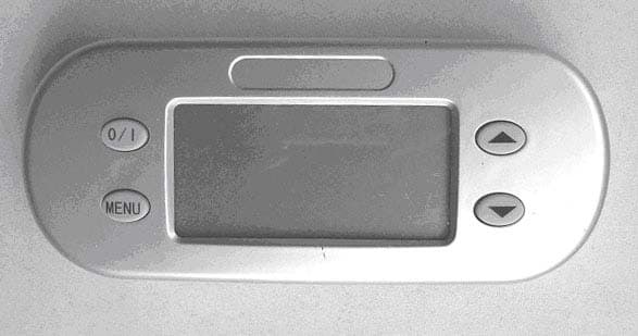
Click to zoom
Application Details
- Equipment Class
- DSC - Part 15 Security/Remote Control Transmitter
- Date of Grant
- Jan 17, 2006
- Application Purpose
- Original Equipment
- Date of Application
- Jan 17, 2006
- Equipment Note
- Remote Control
- Frequency Range
- 315.08000000 - 315.08000000
- Country
- China
Documents & Files
Document Text
Text extracted from the exhibit documents filed with the FCC. Open a document above to read the original.
Users Manual
1 OF 7 WUXI HUTEC Functional Specification Product: Dehumidifier Remote-Control Type: HJ-CSJ63/64/65/66/81/82 Customer: W C Wood Company Limited Rev: A By: Jimmy.Liu Date: 26th Aug,2005 Warning: Changes or modifications not expressly approved by the party responsible for compliance could void the user's authority to operate the equipment. A. Brief There are three parts of the Dehumidifier Remote-Control. a. Electrical source board (Same as the normal dehumidifier: 4-75517-101, 4-75517-102) - Voltage rage: 115VAC / 60Hz,220AC /50Hz b. Receiving-Control(HJ-CSJ63/64/65/66) - Receiving-Control receives the instruction from the Transmitting-Control and controls the fan and compressor to be on or off. c. Transmitting-Control(HJ-CSJ81/82) - User sets the RH on Transmitting-Control, and the Transmitting-Control emits the instruction to Receiving-Control to open or close compressor according to the ambient RH and user’s RH set-point. - In order to save power, the transmitting-control sleeps 57s and wakes up 3s per minute normally. In sleep status, the transmitting-control does nothing , not tests the RH or temperature ,not emits instruction to Receiving-control, not changes the LCD. So the current is lower than 80uA in sleep status. You can wake up transmitting-control by pressing any key while it’s in sleep status. While time reaches per minute or user presses any key , the transmitting-control wakes up. In wake up status, transmitting-control tests the RH and the temperature, then it decides what to do. The current is about 4mA in wake up status. - The distance of the remote is about 15m indoors or above 20m outdoors. B. Functional Specification 2 OF 7 Part a Electrical source board Same as the normal dehumidifier: 4-75517-101,4-75517-102,not described here. Part b Receiving-Control Four Led Lights: Fan-speed-high light (LED1), Fan-speed-low light (LED2), Power-on light (LED3), Bucket-full light (LED4.RED)/Low-temp light (LED4.GREEN) TWO Buttons: Power button(SW1), Fan-speed button(SW2) TWO Temperature sensors: ambient-temperature sensor, coil-temperature sensor ONE Buzzer: bucket-full alarm Figure.1 Receiving-Control 1. Normal mode 1) When first time turning on power to the receiving-control, the receiving-control begin to work with the power-on light on according to the instruction from the transmitting-control. If the remote communicates error for 30 minutes, the power-on light flashes and the audible alarm (Bi-Bi) will be generated. After communicate error, you can press Power button and Fan-speed button at receiving-control. Fan will run at the speed according to your selection. Compressor will keep on for 52 minutes and keep off for 8 minutes. 2) When the fan speed is chosen high on the transmitting-control, the fan-speed-high light is on and the high-speed fan runs if it is enable. When the fan speed is chosen low on the transmitting-control, the fan-speed-low light is on and the low-speed fan runs if it is enable 3) Compressor must lag behind fan for 4 minutes. Once the compressor quits running, it needs 4 minutes of interval if it should be turn on again. 4) When bucket full condition is detected for 2 seconds, compressor & fan will be turned off sequentially. Then bucket-full light will be on and the audible alarm (1s on/1s off) will be generated every hour. 5) The buzzer is able to alarm only because being set enable from transmitting-control. 3 OF 7 2. Very-Low-temp mode If ambient temperature is below 4’C for 4mins, the control stops, the four LED lights flash until the ambient temp is above 5’C for 8mins. 3. Low-temp mode When the ambient temperature is lower than 15’C and lasts over 10 minutes continuously, the receiving-control will automatically enter into the low-temp mode and the low-temp light begins flash. In the low-temp mode, there are two conditions: Condition A: If humidity does not reach your set point, the compressor runs 52mins on/8mins off. At the end of the cycle, the receiving-control checks the coil-temp. If the coil-temp is above 5’C, the compressor continues 52mins on until the humidity reach the Set-point. If the coil-temp is below 5’C, the compressor keeps stopping and fan runs to defrost for 8mins again. At the end of the cycle, check the coil-temp again. Condition B: If humidity reaches the set point in 52mins, the compressor stops and the fan runs, the receiving-control runs defrost for 4mins. at the end of the 4mins, check the coil-temp. If the coil-temp is above 5’C, the compressor and the fan keep stopping unless humidity increases to the set point again. If the coil-temp is below 5’C, the receiving-control runs defrost for 4mins again, and then check the coil-temp. Once the ambient temperature is above 18’C for 10mins, the remote enter the normal-mode. 4. Defrost mode: When the coil temperature falls below 2’C more than 10 minutes, the receiving-control will automatically enter ‘Defrost mode’. In ‘Defrost Mode’, the compressor will be turned off, the fan will continue running with the selected fan speed. The compressor remains off until coil temperature rises to 9’c or higher more than 10 minutes. (Note: the defrost point is not decide, maybe is 2’C and 9’C, 4’C and 10’C, 6’C and 11’C.) 5. Fail-safe mode If the coil temperature sensor and ambient temperature sensor fail to work properly, the control will run in a fail-safe mode. The fan will run at the speed you select and the compressor will cycle with 52 minutes on / 8 minutes off sequence. 6. Self-test mode While power is off, press Fan-speed button and Power button at the same time for 3 seconds, you will see all LED light on and the buzzer alarms for 1 sec. It means the 4 OF 7 receiving-control has entered the self-test mode. Then you can test the parts of the receiving-control one by one. Press fan-speed button, fan-speed-high light is on and high speed fan runs. Press fan-speed button, fan-speed-low light is on and low speed fan runs. Press fan-speed button, power-on light is on and compressor &…
Text truncated - open the document above for the full version.
Block Diagram
123456 A B C D 654321 D C B A Title NumberRevisionSize B Date:5-Jan-2006 Sheet of File:E:\工作区\遥控除湿机\protel\csj.ddbDrawn By: AC230V AC230V-AC12V AC12V HIGH FAN LOW FAN COMPRESSOR HIGH FAN LOW FAN COMPRESS controlled by receive board controlled by receive board controlled by receive board POWER BOARD A C 1 V + 2 A C 3 V - 4 AC12V-DC5V +5V MCU ON/OFF SPEED Coil Temperature Room Temperature Water Overflow High Fan Low Fan Compressor Full Bucket Low Temp RF Memory DC3V LCD Display Memory Relative Humidity Room Temperature ON/OFF MODE UP DOWN RF MCU RECEIVER BOARDREMOTE BLOCK DIAGRAM DC14V DC14V DC14V PDF 文件使用 "pdfFactory" 试用版本创建 www.fineprint.com.cn
External Photos
Front View Rear View
Internal Photos
Uncovered Main Board Front View with Display Main Board Front View RF Module View RF Module Board Front View RF Module Board Rear View
Operational Description
Transmitting control Four Buttons: Power button(1) Mode button(2) “UP” button (10) “DOWN” button(11) LCD: Fan speed high(7), Fan speed low(8), RH setting bar(6),ambient temperature(3), ambient RH(4),buzzer(9) and full-bucket(5). Two Sensors: ambient temperature sensor, RH sensor 1. Power-off mode User can shut down the power at any time. When the power is shut, LCD will be off, and all displays & outputs on receiving-control will be shut down also. 2. Power-On Mode (Operating Mode) LCD is on, ambient temp and ambient RH will be displayed. RH setting bar shows the user set-point, initial is 35%. Fan speed shows the previous set fan speed, initial is fan speed high. Compressor & fan will be on if the ambient RH is 5% higher than user set point. Once the room RH reaches 3% below the user set point, compressor & fan will be turned off sequentially. 3. Fail-safe mode If either the humidity sensor or thermistor fails to work properly, the control will run in fail-safe mode. The fan will run with user selected fan speed and the compressor will cycle with 52 minutes on / 8 minutes off sequence. 6 OF 7 4. Setup mode The control will automatically return to Operating Mode if the setup process is not completed within 2 minutes. All the changes made by user will be effective immediately. However, compressor on/off sequence MUST follow the Criteria of compressor control. a. Fan speed setup Setup Mode can be activated by pressing ‘MODE’ button in Operating Mode. All icons on LCD display will be off except the icons of fan speed, the icon of selected fan speed will flash. ‘UP’ & ‘DOWN’ button can be used to change the fan speed. b. RH setup Pressing ‘MODE’ button again, RH setting bar with numbers will be displayed. ‘UP’ & ‘DOWN’ button can be used to change the RH set point. RH blocks will be showed as solid & flash with selected RH set-point on LCD display. Once the RH bar reaches the highest block, the control will switch to Fan-Only Mode, compressor will be turned off irrelevant to the ambient humidity. Once the RH bar reaches the lowest block, the control will switch to Continuous Mode, compressor will be always on irrelevant to the ambient humidity. c. Temperature Unit Pressing ‘MODE’ button again, temperature readout will be displayed with selected unit (‘C or ‘F). ‘UP’ & ‘DOWN’ button can be used to change the unit. d. Buzzer setup Pressing ‘MODE’ button again will activate buzzer setup, ‘UP’ & ‘DOWN’ button can be used to set buzzer on or off. . e. Exit from Setup-Mode Pressing ‘MODE’ button again will bring the control back to Operating Mode. 5. Yard Mode ONE TO ONE : First, you keep the receiving-control and transmitting-control off. Then press ‘UP’ & ‘MODE’ at the same time on transmitting-control for 2 sec and the transmitting-control will emit “one to one” yard. Finally, you press fan-speed button on receiving-control. Now you will hear a “BI”, it means the “one to one” is ok. In ONE TO ONE mode, one transmitting-control just controls one receiving-control. ONE TO ALL: First, keep the receiving-control and transmitting-control off. Then press ‘UP’ & ‘MODE’ at the same time and press “POWER” in succession. Now, the 7 OF 7 transmitting-control is on and emit “one to all” yard. All receiving-control beside the transmitting-control will receive the yard and be controlled by this transmitting-control. It means “ONE TO ALL” is ok. In ONE TO ALL mode, one transmitting-control just controls all receiving-control. 6. Self-test Mode Keep the LCD off, press ‘UP’ & ‘DOWN’ at the same time and press “POWER” in succession. All symbol on LCD will light, it means the self-test mode. 1) Test LCD Press ‘UP’ ,all clear except “88°E” & “88%RH”. Press ‘UP’, all clear except “BUCKET” & “BUZZER”. Press ‘UP’, all clear except “RH setting bar”. Press ‘UP’ ,all clear except “big fan” , ”small fan” , ”sun” and “compressor”. Press ‘UP’, all light. Press ‘UP’, it recycle from “88°E” & “88%RH”. Press ‘DOWN’ will recycle also. 2) test RH and temp Press ‘MODE’, all clear except RH and the ambient temp. It shows the ambient RH and ambient temperature. 3) quit self-test mode Press ‘MODE’, will quit Self-test Mode and enter Operating Mode. You can quit Self-test Mode and enter Operating Mode at any time if you press “POWER”
Schematics
123456 A B C D 654321 D C B A Title NumberRevisionSize B Date:17-Jan-2006Sheet of File:F:\工作区\遥控除湿机\protel\csj.ddbDrawn By: R1 10K Q1 NPN 315 CRYSTAL R2 510RC3 8.3---8.6PF C2 4.0--4.2PF C4 10PF R3 10K Q2 NPN C6 1NF(1035PF) C7 8.2---8.8PF C8 2.1---2.2PF C10 12PF C11 1.5---1.9PF C13 8.2---8.5PF LP? ANTENNA C14 1NF(1035PF) VC VC VCCVC TX L1 10MH L2 10MH L3 7.5---8MH L4 10MH IF 433 THEN R1=100K,R2=30K IF 315 THEN R1=47K,R2=15K PDF 文件使用 "pdfFactory" 试用版本创建 www.fineprint.com.cn
Schematics
GTA3.222.155/156YL GTA3.222.155/156YL 批准/Ratifier 工艺/Technics 审核/Auditing 设计/Compile版本号/Rev重量/Weight比例/Scale 第 1 张共 1 张 A 原 理 图/Schematics HJCSJ81/82 C O M 0 5 5 C O M 1 5 4 C O M 2 5 3 C O M 3 5 2 S E G 0 5 1 S E G 1 5 0 S E G 2 4 9 S E G 3 4 8 S E G 4 4 7 S E G 5 4 6 S E G 6 4 5 S E G 7 4 4 S E G 8 4 3 S E G 9 4 2 S E G 1 0 4 1 S E G 1 1 4 0 S E G 1 2 3 9 S E G 1 3 3 8 S E G 1 4 3 7 S E G 1 5 3 6 V3 56 V2 57 V1 58 C1 59 C0 60 V S S 1 X I N 2 X O U T 3 T E S T 4 V D D 5 X T I N 6 X T O U T 7 R E S E T 8 P60/AIN0 10 P13/INT2 23 P62/ECNT 12 P63/AIN3 13 P65/AIN5 15 P66/AIN6 16 V A R E F 1 8 A V D D 1 9 P10 20 P55 33 P56 34 P30 61 P31 62 P32 63 P33 64 U1 TMP86C820 C O M 1 1 C O M 2 2 C O M 3 3 C O M 4 456789 1 0 1 1 1 2 1 3 1 4 1 5 1 6 1 7 1 8 1 9 2 0 LCD C1 104 C6 104 C5 104 C7 104 Y1 4M R1 1M Y2 32K C3 30p C4 30p R3 100K +3V +3V X1 X2 R4 100K R5 100K R6 100K R7 100K SW1 1/0 SW2 MODE SW3 UP SW4 DOWN C8 102 C11 104 C12 104 C13 104 C14 104 C15 104 C16 104 +3V R8 100K R9 20K R10 100K R11 100K R13 10K R14 100K V S S 1 TR 2 VO 3 RES 4 VC 5 TH 6 DIS 7 V D D 8 U2 555 R15 1K R16 49.9K R17 523K R18 30.1K R19 20K R20 6.04K R21 2K R22 1K C9 104 C10 104 R23 8.06K R24 4.02K J1 J2 J3 J4 J6J5 J7J8 RH1 HS1101 Q1 9012 +3V RP1 10K/25C 传感系统电源开关/Power of Sensor 环境温度/Surrounding Temp 湿度传感/Relative Humidity A0 1 A1 2 A2 3 VSS 4 SDA 5 SCL 6 WP 7 VDD 8 U3 24LC01 +P RF电源/Power of RF RF信号/Data of RF Vout 1 G N D 2 ON/OFF 3 C - 4 Vin 5 C + 6 U5 AAT3110 VCC 1 GND 2 D A T A 3 U4 RF C17 1uF C18 10uF C19 10uF +3V Q3 9013 +5V 3V电池输入 R25 1M R30 100K R31 100K R32 100K R33 10K R34 100K R35 100K R36 100K R37 100K +3V +3V +3V C2 104 D1 4148 +P 65mV 255-5.5=249.5 发放号/NO: 1 OF 1 Battery 3V PDF 文件使用 "pdfFactory" 试用版本创建 www.fineprint.com.cn
Test Report
670 National Avenue, Mountain View, CA 94043 Tel. (650) 988-0900 Fax (650) 988-6647 www.ecmg-global.com FCC CERTIFICATION RADIO MEASUREMENT TECHNICAL REPORT On Model Name: Remote Control Model Numbers : Model (4-75518-002) Remote Control- 115V/HJCSJ 82, 82A, 82B, 82C, 82D Trademark : Hutec FCC ID : TWTHJCSJ82 Prepared for Wuxi Hutec Technology Co., Ltd. According to FCC Part 15 (2004), Subpart C Test Report #: WUX-0512-0115SH-FCC Prepared by: Chris Huang QC Manager: Harry Zhao Test Report Released by: 2005, December 27 th ⎯⎯⎯⎯⎯⎯⎯⎯⎯ ⎯⎯⎯⎯⎯⎯ Harry Zhao Date NVLAP Lab code: 200068-0 ISO/IEC 17025:1999, ISO 9002:1994 Test Location Tests performed at EMC Compliance Management Group (China) in a Certified ANSI Semi-Anechoic Chamber and Shielded Room performed testing. Test Site Location: Jiangsu Electronic Products Supervision & Inspection Institute No 107 Ge lane ZhongQiao WuXi JiangSu, China Tel: 86-510-5140037 Fax: 86-510-5105579 Registration Number: 399439 Accreditation Bodies EMC Compliance Management Group is a fully accredited Test Laboratory for ITE, ISM and Telecommunications Products. In compliance with the site registration requirements of Section 2.948 of the FCC Rules to perform EMI measurements for the general public. Accredited by the National Voluntary Laboratory Accreditation Program for the specific scope of accreditation under Lab Code # 200068-0. Table of Contents DISCLAIMER NOTICE _________________________________________ 1 REPRODUCTION CLAUSE_____________________________________ 1 OPINIONS AND INTERPRETATIONS ___________________________ 1 STATEMENT OF MEASUREMENT UNCERTAINTY ______________ 1 ADMINISTRATIVE DATA _____________________________________ 2 EUT DESCRIPTION ___________________________________________ 3 TYPE OF DERIVER____________________________________________ 3 TEST SUMMARY _____________________________________________ 4 TEST MODE JUSTIFICATION _________________________________ 5 EUT EXERCISE SOFTWARE ___________________________________ 5 EQUIPMENT MODIFICATION _________________________________ 5 TEST SYSTEM DETAILS ______________________________________ 6 CONFIGURATION OF TESTED SYSTEM________________________ 7 EUT SAMPLE PHOTOS OF MODEL (4-75518-002) REMOTE CONTROL- 115V/HJCSJ82C _____________________________________________ 8 ATTACHMENT 1 – ANTENNA REQUIREMENT_________________ 13 ATTACHMENT 2 – RESTRICTED BAND OF OPERATION_______ 16 ATTACHMENT 3 – OPERATION MODE _______________________ 22 ATTACHMENT 4 –FIELD STRENGTH OF FUNDAMENTAL AND SPURIOUS EMISSIONS__________________________________________________ 25 ATTACHMENT 5 – BANDWIDTH _____________________________ 32 EMC Test Report #: WUX-0512-0115SH-FCC Prepared for Wuxi Hutec Technology Co., Ltd. Prepared by EMC Compliance Management Group Page 1 of 35 Disclaimer Notice When government drawing, specification, or other data are used for any purpose other than in connection with a definitely related government procurement operation, the United States Government thereby incurs no responsibility nor any obligation whatsoever; and the fact that the Government may have formulated, furnished, or in any way supplied the said drawing, specifications, or other data, is not to be regarded by implication or otherwise in any manner licensing the holder or any other person or corporation, or conveying any rights or permission to manufacture, use, or sell patented invention that may in any way be related thereto. This report must not be used to claim product endorsement by NVLAP or any agency of the U.S. Government. Reproduction Clause Any reproduction of this document must be done in full. No single part of this document may be reproduced without permission from EMC Compliance Management Group, 670 National Ave., Mountain View, CA 94043. Opinions and Interpretations This test report relates to the abovementioned equipment under test (EUT). Without the permission of EMC Compliance Management Group Test Lab this test report is not permitted to be duplicated in extracts. This test report does not entitle to carry any test mark on this or similar products. The manufacturer has sole responsibility of continued compliance of the device. Statement of Measurement Uncertainty The data and results referenced in the document are true and accurate. The reader is cautioned that there may be errors within the calibration limits of the equipment and facilities that can account for a nominal measurement error. Furthermore, component and process variability of devices similar to that tested may result in additional deviation. EMC Test Report #: WUX-0512-0115SH-FCC Prepared for Wuxi Hutec Technology Co., Ltd. Prepared by EMC Compliance Management Group Page 2 of 35 Administrative Data Test Sample : Remote Control Model Number : Model (4-75518-002) Remote Control- 115V/HJCSJ82, 82A, 82B, 82C, 82D Models Tested : Model (4-75518-002) Remote Control- 115V/HJCSJ82C Trade Mark : Hutec Date Tested : 2005, December 27 th Applicant : Wuxi Hutec Technology Co., Ltd. 4 th Floor, Standard 4 Building, Liyuan Economic Development Zone Wuxi, Jiangsu 214072 Telephone : 86-510-85162340 Fax : 86-510-85165555 Manufacturer : Wuxi Hutec Technology Co., Ltd. 4 th Floor, Standard 4 Building, Liyuan Economic Development Zone Wuxi, Jiangsu 214072 EMC Test Report #: WUX-0512-0115SH-FCC Prepared for Wuxi Hutec Technology Co., Ltd. Prepared by EMC Compliance Management Group Page 3 of 35 EUT Description Wuxi Hutec Technology Co., Ltd. Model number Model (4- 75518-002) Remote Control-115V/HJCSJ82C (referred to as the EUT in this test report) is a Remote Control. Type of Deriver Model(4-75518-002)Remote Control-115V/HJCSJ82, 82A, 82B, 82C, 82D are exactly same except the temperature point that is set in software to protect the compressor. See the below: HJCSJ81, compressor will enter low temperature compressor protect mode at 15 °C. HJCSJ81A, compressor will enter low temperature compressor protect mode at 17 °C. HJCSJ81B, compressor will enter low temperature compressor…
Text truncated - open the document above for the full version.
Contact Information
Applicant
Jimmy Liu(R&D Engineer)
Test Firm
Jiangsu Electronic Products Supervision InstituteMinliang Wang
Technical Specifications
| # | Rule Parts | Frequency Range | Power Output |
|---|---|---|---|
| 1 | 15.231 | 315.08 MHz - 315.08 MHz | - |