TWXCH-W8082.4GHz Digital Cordless Telephone
Cheung Hung Electronics Ltd.
Click to zoom
Application Details
- Equipment Class
- DSS - Part 15 Spread Spectrum Transmitter
- Date of Grant
- Jan 16, 2006
- Application Purpose
- Original Equipment
- Date of Application
- Jan 16, 2006
- Equipment Note
- 2.4GHz Digital Cordless Telephone
- Frequency Range
- 2401.00000000 - 2482.00000000
- Company
- Cheung Hung Electronics Ltd.
- Country
- Hong Kong
Documents & Files
Document Text
Text extracted from the exhibit documents filed with the FCC. Open a document above to read the original.
Users Manual
2.4GHz Digital Cordless Phone Instruction Manual CH-W808 In order to obtain the best conversation quality, it is not proper to consume the power supply with other electric appliance on one power source Please read this manual before using this device and keep it well for future use ST 1 0 2 ABC GHI 5 JKL 6 MNO 7 PQRS 8 TUV 9 WXYZ 3 DEF 4 UP R E D IA L P A U S E F L A S H D E L E T E END TALK SPEAKER PAGE MENU LDS MUTE DOWN ~ 1 ~ CONTENTS MAIN FEATURES................................................................................... 2 PACKAGE CONTENTS........................................................................3 TELEPHONE SKETCH & PARTS DESCRIPTION...............3-4 INSTALLATION INSTRUCTION.........................................5 LCD SCREEN..........................................................................6 SYMBOL DESCRIPTION.........................................................6 MENU OVERVIEW.....................................................................7 MENU SETTING...........................................................8 REGISTER AND DEREGISTER.....................................8 LOCAL CODE..........................................................9-10 BACKLIGHT TIME SETTING......................................10 TONE/PULSE SELECTABLE SETTING.......................11 AUTO TALK AND ANY KEY TALK SETTING....................11 RECALL TIME DURATION SETTING 100MS/300MS/600MS..............................................12 HOST NAME SETTING...............................................12 LANGUAGE SETTING....................................................13 BRIGHTNESS CONTRAST SETTING..............................13 EDIT THE ID REGISTER NUMBER..................................14 TIME FORMAT SETTING....................................... .........14 TIME SETTING................................................................15 DEFAULT VALUE SETTING............................... .................15 PHONE BOOK SETTING .............................................16-18 NON-DISTURBANCE SETTING..................................18-19 ALARM CLOCK SETTING..........................................19-20 CALL BARRING..............................................................20 BABY C ALL SETTING.......................................................22 CALLER ID REVIEW,/REDIAL/STORE/DELETE......................24 OUTGOING CALLS REVIEW / REDIAL / STORE / DELETE.....25- 26 RINGER TONE SETTING.................................................27-28 RINGER TONE VOLUME SETTING...................................28-29 PAGE TONE MELODY SETTING................................29 KEYPAD TONE SETTING...........................................29 DIAL CALL....................................................................30 ANSWER CALLS....................................................................30 CALL WAITING............................................................. 30 BASE PAGE HANDSET ..........................................................31 INCOMING CALLS AND OUTGOING CALLS FUNCTIONS....31 PRE-DIALING FUNCTION ....................................................31 RINGER VOLUME SETTING........................................32 REDIAL........................................................................32 PAUSE..........................................................................32 RECALL MODE............................................................32 HOLD-ON STATE OF THE TELEHPONE......................................32 MAIN TECHNOLOGY PARAMETER...........................................33 MAINTENANCE.........................................................................34 TROUBLE SHOOTING................................................................35 CONTENTS WALKIE TALKIE....................................................................21 ROOM MONITOR................................................................... 23 LDS OPERATION INSTRUCTION ..........................................8 KEYPAD LOCK SETTING....................................................32 ~ 1 ~ CONTENTS MAIN FEATURES................................................................................... 2 PACKAGE CONTENTS........................................................................3 TELEPHONE SKETCH & PARTS DESCRIPTION...............3-4 INSTALLATION INSTRUCTION.........................................5 LCD SCREEN..........................................................................6 SYMBOL DESCRIPTION.........................................................6 MENU OVERVIEW.....................................................................7 MENU SETTING...........................................................8 REGISTER AND DEREGISTER.....................................8 LOCAL CODE..........................................................9-10 BACKLIGHT TIME SETTING......................................10 TONE/PULSE SELECTABLE SETTING.......................11 AUTO TALK AND ANY KEY TALK SETTING....................11 RECALL TIME DURATION SETTING 100MS/300MS/600MS..............................................12 HOST NAME SETTING...............................................12 LANGUAGE SETTING....................................................13 BRIGHTNESS CONTRAST SETTING..............................13 EDIT THE ID REGISTER NUMBER..................................14 TIME FORMAT SETTING....................................... .........14 TIME SETTING................................................................15 DEFAULT VALUE SETTING............................... .................15 PHONE BOOK SETTING .............................................16-18 NON-DISTURBANCE SETTING..................................18-19 ALARM CLOCK SETTING..........................................19-20 CALL BARRING..............................................................20 BABY C ALL SETTING.......................................................22 CALLER ID REVIEW,/REDIAL/STORE/…
Text truncated - open the document above for the full version.
Users Manual
HOUR OFF TONE TONE NONDISTURB PHONE BOOK FUNCTION NONDISTURB ALARM1 OR ALARM2 SELECT OFF SELECT ON SET TIME ~ 19 ~ Displaying : Displaying : Displaying : Displaying : Displaying : Displaying : Displaying : Displaying : Displaying : ALARM CLOCK SETTING 1.At standby mode (handset), press to enter menu setting 2.Press or to select "FUNCTION" 3.Press and LCD screen displays " NONDISTURB" 5.Press to confirm and enter sub-menu 6.Press or to select alarm clock on or alarm clock off 7.If select alarm clock on, press and digit on right below side is flashing 4.Press or to select ALARM 1 or ALARM 2 7.Press and hold continuously up to 2S' to effect fast setting of 8 hours non-disturba- nce, LCD screen displays ,it indicates the telepone enter 8 hours non-disturbance state, press and hold again continuously up to 2S' to fast end 8 hours non-disturbance and disappear, Press to confirm after a crisp tone "BI" heard, it indicates the setting succeed and the non-disturbance icon" "will display on LCD screen, press END to return to stan- dby mode, or press FL/DEL to return to upper menu Press to display "NON DISTURB Press to display "HOUR OFF" Press or to select non-disturbance time duration ranged 1~16 hours or select OFF to end non-disturbance D O W N U P D O W N U P D O W N U P D O W N U P FUNCTION SETTING INSTRUCTION ~ 18 ~ 7.Review phone memory >Press three times, LCD screen display "NEW ENTRY" >Press to select MEMORY/STATUS >Press to confirm and LCD displays "000/100", it indi- cate no memory stored (max. Store capacity is 100 groups) >Press END to return standby mode or press FL/DEL to return to upper menu after reviewed, NON-DISTURBANCE SETTING 1. At standby mode (handset), press to entry menu setting 2.Press or to select "FUNCTION" 6.SPEED DIAL >Press or to select the stored record >Press twice to enter phone book mode >Press to confirm the select >Press to enter "HOT KEY 0 TO 9", icon "-" is flashing, >Press to confrim, after a crisp tone "BI" heard, it indicate the keypad assigning for speed dial succeed >In case of the stored number required to dial out, at standby mode, press and hold keypad 0~9 up to 2S' to display the stored number, press or to dial out directly >Input the single digit ranged 0~9 to confirm the assigned keypad position( if there is a digit exist before the icon "-", it indicate the keypad assigned for speed dial already, the assigned keypad position can delete by press button, or select the other keypad for store >Press or to select "SPEED DIAL" NEW ENTRY HOT KEY O TO 9 SPEED DIAL NEW ENTRY MEMORY STATUS 000 / 100 FUNCTION PHONE BOOK JACK 8888888 D O W N U P D O W N U P U P Displaying : Displaying : Displaying : Displaying : Displaying : Displaying : Displaying : Displaying : Displaying : D O W N U P FUNCTION SETTING INSTRUCTION MENU MENU MENU MENU MENU MENU MENU MENU MENU MENU MENU MENU MENU MENU MENU PHONE BOOK FUNCTION NONDISTURB FUNCTION ON WT MODE HANDSET 1 CALLING _ CALLING ANDSET 2H WT MODE HANDSET 1 OR 2 WAKLIE TALKIE ~ 21 ~ Displaying : Displaying : Displaying : Displaying : Displaying : Displaying : Displaying : Displaying : Displaying : Displaying : Displaying : 1.At standby mode, press to enter menu setting >Press or to select "FUNCTION" >Press to confirm and LCD screen displays NONDISTURB >Press or to select WALKIE TALKIE D O W N U P D O W N U P FUNCTION SETTING INSTRUCTION CALL BARRING PHONE BOOK FUNCTION NONDISTURB CALL BARRING INPUTPIN BARRING NUMBER BARRING NUMBER ~ 20 ~ Displaying : Displaying : Displaying : Displaying : Displaying : Displaying : Displaying : 8.Press or to select alarm time duration by hour, press to confirm, press or to select alarm time duration by minute 9.Press to confirm after a crisp tone "BI" heard, it indicate the setting succeed, press END to exit and return to standby mode 1.At standby mode, press to enter menu setting 2.Press or to select "FUNCTION" 3.Press to confirm and LCD screen displaying "NONDISTURB" 5. Press to confirm and LCD screen displays "INPUT PIN" enter pin number 1234 (default pin is 1234), 6.Press to confirm and LCD screen displays BARRING NUMBER 4.Press or to selectCALL BARRING 7.Press to confirm and the icon "-" is flashing 8.Input telephone number for call barring (max.number length is 6 digits), press to confirm,after a crisp tone "BI" heard, it indicates the setting succeed 9.Press FL/DEL to return to upper menu, or press END to return to standby mode Notice: you can store max.5 different numbers for call barring. Example--if you programmed 98, then phone will bar all numbers starting with 98xxxxxx, if the full number is prog- rammed for barring, then only that number will bared. FUNCTION SETTING INSTRUCTION D O W N U P D O W N U P D O W N U P D O W N U P Notice: In case of the Alarm Clock function is programmed, press any key to end when the telephone is alarming WALKIE TALKIE Notice: the Walkie Talkie function can be effective only based on 2 or more handsets performed. >Press till display "FUNCTION ON" >Press to confirm, after a crisp tone "DI" heard and LCD displays "WT MODE HANDSET 1", it indicates the setting succeed 2.Repeat the setting process as handset 1 to process other handsets, till LCD displays "WT MODE HANDSET 2", or "WT MODE HANDSET 3", it indicate the setting succeed WT MODE HANDSET 2 3.Once Walkie Talkie function programmed on all handsets, if you want to effect Walkie Talkie on handset 1 or handset 2, press TALK button on handset 1 or 2 till LCD displays "CALLING"and the icon "-" is flashing 4.Input the handset code accordingly (e.g.: input "2"for hand- -set 2) and LCD will display "CALLING HANDSET 2" 5.Handset 2 will ring, press TALK button on handset 2 which is being called to effect Walkie Talkie 6.Press END button on any Walkie Talkie handset to quit the Walkie Talkie and return to standby state 7.How to remove Walkie Talkie function: press button on handset till display "WT MODE OFF " CALLING ANDSET 1H 8.Press again till a crisp tone "DI" heard, it indicates the Walkie Talkie functio…
Text truncated - open the document above for the full version.
Block Diagram
HANDSET BLOCK DIAG RAM GND 10..368MHz LRS+ RECEIVER LRS- MIC+ MIC GND P17 P1 ANT1 P26 P4 P22 P5 P21 P6 P20 P7 ANT2 MCU P18 P9 P15 P2 P24 P17 P23 P16 EXTERNAL MCU MAIN MCU CRK-RF P37 SCL P12 P36 SDA RESET UTX URX SC1443PP CRKIVD 3V RFCIKP (10.368MHz) RFRST LE SIO RF 2.4G SK TDO RFCLKM/RSSI ANTSELECT1 ANTSELECT2 CHARGE CONTROL SIGNALS Voltage Increasement Q2.R1.L1.D9 BAT 2.4V LCD KEY BOAD EEPROM 24C64 BASE BLOCK DIAGRAM GND 10.368MHz 3.1V P17 3.1V P1 AC/DC VBAT1 P26 2.5V P4 ADAPTER P22 P5 ANT2 P21 P6 CHARGINCT CHARGE DET P20 P7 TERMINALS P19 P8 HOOK(R3) P18 P9 ANT1 PULSE P15 P2 CID IN P MICN/CIDOUT P24 P16 PSTN/CO LINE CID INN REF P23 P17 ADO RINGING CRK-RF RXAF CHARGE LED TXAF HOOK LED MAIN MCU P46 CPU SC1443FPCRK P44 P1 P62 P60 P56 P52 P64 P55 P59 P8 P53 P61 VDD RFCIKP(10.368MHz) RFRST LE SIO RF 2.4G SK RDI TDO RFCLKM/RSSI ANTSELECT2 ANTSELECT1 3.1 VOCTAGE REGULATOR CIRCUIT SUPPLY LED CHARGE LINE INTER FACE EEPROM 24C16
External Photos
Cheung Hung Electronics Ltd. FCC ID: TWXCH-W808 Report # R0511174Exhibits.doc FCC Part 15.247 Test Report EXHIBIT C - EUT PHOTOGRAPHS Handset of EUT: EUT – Top View Handset of EUT: EUT – Rear View Cheung Hung Electronics Ltd. FCC ID: TWXCH-W808 Report # R0511174Exhibits.doc FCC Part 15.247 Test Report Base of EUT: EUT –Top View Base of EUT: EUT –Front View Cheung Hung Electronics Ltd. FCC ID: TWXCH-W808 Report # R0511174Exhibits.doc FCC Part 15.247 Test Report Base of EUT: EUT –Side View Power Supply View
ID Label/Location Info
EXHIBIT A - FCC ID LABEL INFORMATION Proposed FCC ID Label Proposed Label Location on EUT Back View of EUT/FCC ID Label Base of EUT Handset of EUT Industry Canada Industrie Canada IC: 6301A-CHW808 FCC ID: TWXCH-W808 This device complies with Part 15 o the FCC Rules. Operation is subject to the following two conditions: (1) this device may not cause harmful interference, and (2) this device must accept any interference received, including interference that may cause undesired operation.
Internal Photos
Cheung Hung Electronics Ltd. FCC ID: TWXCH-W808 Report # R0511174Exhibits.doc FCC Part 15.247 Test Report Handset of EUT: EUT –Chassis off View Handset of EUT: EUT –Component View Cheung Hung Electronics Ltd. FCC ID: TWXCH-W808 Report # R0511174Exhibits.doc FCC Part 15.247 Test Report Handset of EUT: EUT –Solder View Base of EUT: EUT –chassis off View Cheung Hung Electronics Ltd. FCC ID: TWXCH-W808 Report # R0511174Exhibits.doc FCC Part 15.247 Test Report Base of EUT: EUT–Component View Base of EUT: EUT–Solder View Cheung Hung Electronics Ltd. FCC ID: TWXCH-W808 Report # R0511174Exhibits.doc FCC Part 15.247 Test Report EUT (Base) Transceiver Close-up View EUT (Handset) Transceiver Close-up View
Operational Description
1. Handset 1.1 TX MIC signal output to U2 (SC1443PP) via pin 72(MIC),pin 73(VREF).when TX signal is received by U2, then processing via A/D, then output to RF by pin 22(TDO).RF send TX to BASE. Bandwidth 20db<864kHZ 1.2 RX When RF receive the signal, after demodulation then send to baseband controller(PIN23 HS_RDI). baseband controller process the signal and transform to voice output to receiver(via pin 66 HS_LSR/REF- ,PIN 67 HS_LSR/REF ) or speaker(pin30 HS_PAOUTM,PIN32 HS_PAOUTP) Related component: C390,SPK1,C46,C65,C48,SPK2,C40,C39,C47 1.3 2.5V REGULATOR 2.5v regulator supply DC power for RF+2.5V,VDDID(PIN38,PIN2,PIN63). Related components:Q4,C42,C10,R24. 1.4 3.0V REGULATOR 3.0v regulator supply DC power for VMCU.BACKLIGHT LED. Related components:U2,Q2,D9,L1,R1,C3,C37,C4,Q6,R36,R35,R34,R33,R28,C69. 1.5 2.4V REGULATOR 2.4v regulator supply DC power for RF(PA2V40.U2(PIN31)VDDPA.VBATT1 Related components:C2,R23,C43,C34 C63 C64,C44,R3. Bandwidth 20db<864kHZ 2. Base 2.1 TX Telephone line signal output to U2 (SC1443FP) via pin 59.the signal processed by U2 then output to RF module via pin 18. Bandwidth 20db<864kHZ 2.2 RX RF received the signal, after demodulation then send to U2 via pin 19.U2 process the signal and transform to voice output to telephone line via pin53. Related components: Q2,R11,R12,R8,R7,C54,R10,C5,R9,C66,C6,R14,C7,C24,C76,C67. 2.3 3.1V REGULATOR Regulator U3 supply 3.1V power for base as well as PA2V4 and +3.1V. 2.3 2.5V REGULATOR Regulator Q5 supply 2.5V for base as well as RF(+2.5V) and U2(PIN30,PIN2U1(PIN5). 2.4 Ringer detection the ringer signal to U2 pin 60,pin52. Then send to handset Related component: U2,R1,R2,C3,C4,R24,C23,R25,C25. Bandwidth 20db<864kHZ
Operational Description
Ch-w808 Frequency Table Channel Ch#HEX Frequency Channel Ch#HEX Frequency 1 0 2401.056 48 2F 2443.392 2 1 2402.784 49 30 2444.256 3 2 2403.648 50 31 2445.120 4 3 2405.376 51 32 2445.984 5 4 2406.240 52 33 2446.848 6 5 2407.104 53 34 2447.712 7 6 2407.968 54 35 2448.576 8 7 2408.832 55 36 2449.440 9 8 2409.696 56 37 2450.304 10 9 2410.560 57 38 2451.168 11 A 2411.424 58 39 2452.032 12 B 2412.288 59 3A 2452.896 13 C 2413.152 60 3B 2453.760 14 D 2414.016 61 3C 2454.624 15 E 2414.880 62 3D 2455.488 16 F 2415.744 63 3E 2456.352 17 10 2416.608 64 3F 2457.216 18 11 2417.472 65 40 2458.080 19 12 2418.336 66 41 2458.944 20 13 2419.200 67 42 2459.808 21 14 2420.064 68 43 2460.672 22 15 2420.928 69 44 2461.536 23 16 2421.792 70 45 2462.400 24 17 2422.656 71 46 2463.264 25 18 2423.520 72 47 2464.128 26 19 2424.384 73 48 2464.992 27 1A 2425.248 74 49 2465.856 28 1B 2426.112 75 4A 2466.720 29 1C 2426.976 76 4B 2467.584 30 1D 2427.840 77 4C 2468.448 31 1E 2428.704 78 4D 2469.312 32 1F 2429.568 79 4E 2470.176 33 20 2430.432 80 4F 2471.040 34 21 2431.296 81 50 2471.904 35 22 2432.160 82 51 2472.768 36 23 2433.024 83 52 2473.632 37 24 2433.888 84 53 2474.496 38 25 2434.752 85 54 2475.360 39 26 2435.616 86 55 2476.224 40 27 2436.480 87 56 2477.088 41 28 2437.344 88 57 2477.952 42 29 2438.208 89 58 2478.816 43 2A 2439.072 90 59 2479.680 44 2B 2439.936 91 5A 2480.544 45 2C 2440.800 92 5B 2481.408 46 2D 2441.664 93 5C 2482.272 47 2E 2442.528
Test Report
Note: The test report is specially limited to the above company and this particular sample only. It may not be duplicated without prior written consent of Bay Area Compliance Laboratory Corporation. This report must not be used by the client to claim product certification, approval, or endorsement by NVLAP, NIST or any agency of the US Government. FCC PART 15.247 EMI MEASUREMENT AND TEST REPORT For Cheung Hung Electronics Ltd. Unit 4, 15/F, North Point Asia-pac Centre, No.28 A Java Road, North Point, Hong Kong FCC ID: TWXCH-W808 This Report Concerns: Original Report Equipment Type: 2.4GHz Cordless phone Test Engineer: Oscar Au Report No.: R0511174 Report Date: 2006-1-6 Reviewed By: Snell Leong Prepared By: Bay Area Compliance Laboratory Corporation (BACL) 230 Commercial Street Sunnyvale, CA 94085 Tel: (408) 732-9162 Fax: (408) 732 9164 Cheung Hung Electronics Ltd. FCC ID: TWXCH-W808 Report # R0511174Rpt.doc Page 2 of 78 FCC Part 15.247 Test Report TABLE OF CONTENTS GENERAL INFORMATION.......................................................................................................................................4 PRODUCT DESCRIPTION FOR EQUIPMENT UNDER TEST (EUT) ....................................................................................4 OBJECTIVE...................................................................................................................................................................4 RELATED SUBMITTAL(S)/GRANT(S).............................................................................................................................4 TEST METHODOLOGY..................................................................................................................................................4 TEST FACILITY.............................................................................................................................................................4 SYSTEM TEST CONFIGURATION ..........................................................................................................................6 JUSTIFICATION.............................................................................................................................................................6 EUT EXERCISE SOFTWARE..........................................................................................................................................6 SPECIAL ACCESSORIES.................................................................................................................................................6 SCHEMATICS / BLOCK DIAGRAM..................................................................................................................................6 EQUIPMENT MODIFICATIONS.......................................................................................................................................6 LOCAL SUPPORT EQUIPMENT.......................................................................................................................................6 HOST PC POWER SUPPLY AND LINE FILTERS...............................................................................................................6 CONFIGURATION OF TEST SYSTEM..............................................................................................................................7 TEST SETUP BLOCK DIAGRAM.....................................................................................................................................7 SUMMARY OF TEST RESULTS ...............................................................................................................................8 §15.203 - ANTENNA REQUIREMENT......................................................................................................................9 STANDARD APPLICABLE..............................................................................................................................................9 §15.207 (a)- CONDUCTED EMISSION....................................................................................................................10 MEASUREMENT UNCERTAINTY..................................................................................................................................10 TEST SETUP................................................................................................................................................................10 RECEIVER SETUP........................................................................................................................................................10 TEST EQUIPMENT LIST AND DETAILS.........................................................................................................................10 TEST PROCEDURE......................................................................................................................................................10 ENVIRONMENTAL CONDITIONS..................................................................................................................................10 SUMMARY OF TEST RESULTS.....................................................................................................................................11 CONDUCTED EMISSIONS TEST DATA.........................................................................................................................11 PLOT OF CONDUCTED EMISSIONS TEST DATA...........................................................................................................11 §15.205 & §15.209 - RADIATED EMISSION...........................................................................................................14 MEASUREMENT UNCERTAINTY..................................................................................................................................14 TEST SETUP.........................................................................................................…
Text truncated - open the document above for the full version.
Test Setup Photos
Cheung Hung Electronics Ltd. FCC ID: TWXCH-W808 Report # R0511174Exhibits.doc FCC Part 15.247 Test Report EXHIBIT B - TEST SETUP PHOTOGRAPHS Conducted Emission - Front View Conducted Emission –Side View Cheung Hung Electronics Ltd. FCC ID: TWXCH-W808 Report # R0511174Exhibits.doc FCC Part 15.247 Test Report Handset of EUT: Radiated Emission - Front View Handset of EUT: Radiated Emission - Rear View Cheung Hung Electronics Ltd. FCC ID: TWXCH-W808 Report # R0511174Exhibits.doc FCC Part 15.247 Test Report Base of EUT: Radiated Emission - Front View Base of EUT: Radiated Emission - Rear View
Contact Information
Applicant
Andy Cheung(Manager Director)
Test Firm
Bay Area Compliance LaboratoryJohn Chan
Technical Specifications
| # | Rule Parts | Frequency Range | Power Output |
|---|---|---|---|
| 2 | 15C | 2.40 GHz - 2.48 GHz | 350.00 µW |
Other Applications from Cheung Hung Electronics Ltd.
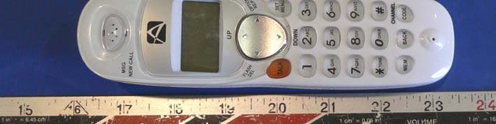
TWXCHA808H
Mar 28, 20062.4 GHz analog cordless phone
Equipment Class
DXX - Part 15 Low Power Communication Device Transmitter
TWXCHA808B
Mar 28, 2006900/2400 MHz Cordless Phone
Equipment Class
DXX - Part 15 Low Power Communication Device Transmitter