TX4RH55ARF Base Station
Remote Solution Co., Ltd.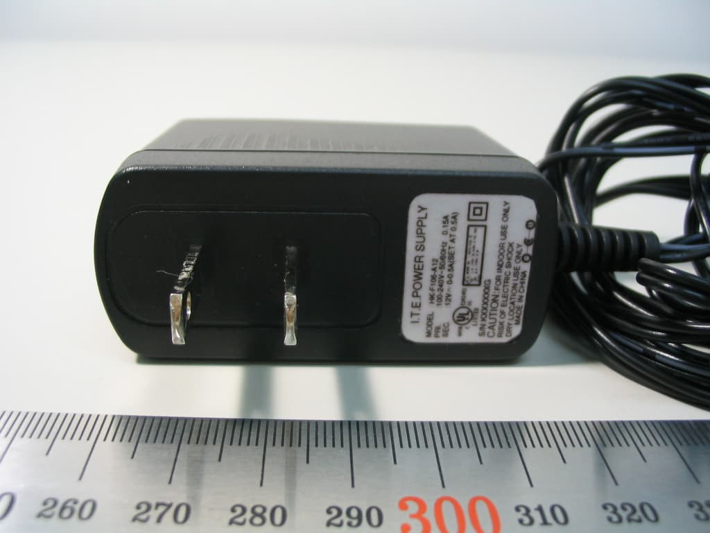
Click to zoom
Application Details
- Equipment Class
- DTS - Digital Transmission System
- Date of Grant
- Nov 05, 2006
- Application Purpose
- Original Equipment
- Date of Application
- Nov 05, 2006
- Equipment Note
- RF Base Station
- Frequency Range
- 2405.00000000 - 2480.00000000
- Company
- Remote Solution Co., Ltd.
- Country
- South Korea
Documents & Files
Document Text
Text extracted from the exhibit documents filed with the FCC. Open a document above to read the original.
Users Manual
- 1 - RH55A,C RF Base Station Quick Start Installation Instructions ATTENTION: Requires the XTR39 to operate. - 2 - Welcome! The RH55A,C base station is the ultimate accessory to the Xantech XTR39 Color LCD remote color. It’s a receiver that accepts the Radio Frequency output of the XTR39 remote and translate it into IR and RS232 command signals that can control virtually any home electronic device. The RH55A,C makes it simple to set up a reliable and sophisticated multi-room control system that is easily controlled by the intuitive LCD touch screen control of the XTR39 remote. Specifications RF Receive Frequency: 2.4GHz RS232 Port Interface: Tx, Rx, and Gnd Addressable Units: 256 RS232 Cable Adapter: DB9 Male to Stereo Plug IR Blaster Range: 30’ Unit Size: 5.0” x 4.75” x 1.0” IR Format Support: XIR1 and XIR2/Library Unit Weight: 4.0 oz Addressable Emitter Output Ports: 4 Unit Color: Black with silver logo Power Requirements: 12Volts DC @ 300mA RoHS Compliant RH55A,C Diagram - 3 - Quick Start Instructions Step 1. Plug the (4) 283M emitters (included) into the RH55A,C. Next, place the 283M emitter head next to the IR eye on the source component to be controlled. Step 2. Plug the RS232 Adapter Cable (if required) into the RH55A,C. Next, connect the DB9 plug to the source component to be controlled. In some instances, a null modem converter may be required. Below is a pin-out of the RS232 Adapter Cable. Step 3. Plug in the power supply to the RH55A,C device. Step 4. Follow the XTR39 Instructions, RH55A,C Addendum and follow the steps to setup the XTR39. Information FCC NOTICE * Section 15.19 Labeling requirements This device complies with part 15 of the FCC rules. Operation is subject to the following two conditions: (1) This device may not cause harmful interference and (2) This device must accept any interference received, including interference that may cause undesired operation. * Section 15.21 Information to user The changes or modifications not expressly approved by the party responsible for compliance could void the user’s authority to operate the equipment. * IMPORTANT NOTE: To comply with the FCC RF exposure compliance requirements, no change to the antenna or the device is permitted. Any change to the antenna or the device could result in the device exceeding the RF exposure requirements and void user’s authority to operate the device. 0197 RH55A,C RF Base Station Quick Start Installation Instructions © 2006 Xantech Corporation This document is copyright protected. No part of this manual may be copied or reproduced in any form without prior written consent from Xantech Corporation. Xantech Corporation shall not be liable for operational, technical, or editorial errors/omissions made in this document. Document Number 08905083X1 Xantech Limited Warranty (Effective for products sold after July 1, 2006) Xantech Corporation (“Xantech”) warrants to the holder of a valid proof of purchase as the first end-user purchaser (“You”), its products to be free from defects in materials and workmanship for the periods specified below from the date of purchase. This limited warranty extends only to You for product purchased and used in the United States of America. For product purchased outside of the United States of America, the terms of this warranty apply EXCEPT that You must contact the Xantech authorized distributor in your region for warranty services. Product is not intended for end user installation. If within the applicable warranty period above You discover such item was not as warranted above and You promptly notify Xantech in writing, Xantech shall repair or replace the items at its option. Xantech may elect which remedy or combination of remedies to provide in its sole discretion. Xantech may use functionally equivalent reconditioned/refurbished/pre-owned or new products or parts under this limited warranty. This warranty shall not apply (a) to product which shall have been installed by other than an authorized Xantech installer, (b) to installed product which is not installed to Xantech’s specifications, (c) to product which shall have been repaired or altered by others than Xantech, (d) to charges for installation or set up or adjustment of customer controls, (e) to product that has suffered normal cosmetic deterioration (f) to product which shall have been subjected to negligence, misuse, abuse, accident, or damage by circumstances beyond Xantech’s control, including, but not limited to, lightning, flood, electrical surge, tornado, earthquake, or any other catastrophic events beyond Xantech’s control, or (g) to product which shall have been subjected to improper operation, connected equipment failure or malfunction, inadequate packing or shipping damage, maintenance or storage, or to other than normal use of service. The foregoing warranties do not cover reimbursement for labor, transportation, shipping, removal, installation, or other expenses which may be incurred in connection with repair or replacement. All claims for product shipping damage must be processes within 3 days of receipt by You. A Xantech Return Authorization (RA) must be obtained from Xantech by You, your installer or your distributor for Product covered under this warranty. Covered product must be sent to Xantech together with proof of purchase, RA number, prepaid and insured to Xantech. Freight collect shipments will be refused. Risk of loss or damage in transit is borne by the sender. Xantech's warranty does not cover Products which have been received improperly packaged, altered, or physically damaged. Products will be inspected upon receipt. Except as may be expressly provided and authorized in writing by Xantech, Xantech shall not be subject to any other obligations or liabilities whatsoever with respect to equipment manufactured or sold by Xantech or services rendered by Xantech. THE FOREGOING WARRANTIES ARE EXCLUSIVE AND IN LIEU OF ALL OTHER EXPRESSED AND IMPLIED WARRANTIES, INCLUDING BUT NOT LIMITED TO I…
Text truncated - open the document above for the full version.
Cover Letter(s)
Chief, Equipment Approval Services Federal Communications Commission PO Box 358315 Pittsburg, PA 15251-5315 Seoul, August 8, 2006 Authorization Letter Dear Sir or Madam: We, Remote Solution Co., Ltd. hereby authorize O.N.R Tech Inc. 463-49, Sinlim-dong, Gwanak-gu, Seoul ,151-870, Republic of Korea To act as our agent and to process and sign on our behalf for equipment authorization under FCC Part 15, Subpart C. This authorization is applicable for the product: RH55A and RH55C with FCC ID: TX4RH55A Sincerely, Signature : Printed Name: Byung-Cheol Kim Title : Manager Company Stamp:
Cover Letter(s)
Federal Communications Commission Authorization and Evaluation Division 7435 Oakland Mills Road Columbia, MD 21046 Seoul, August 8, 2006 REQUEST FOR CONFIDENTIALITY, FCC ID: TX4RH55A Pursuant to Sections 0.457(d)(1)(ii) and 0.459 of the Commission's Rules, the Applicant hereby requests confidential treatment of information accompanying as outlined below: • Schematic drawing • Bill of Materials • Block Diagram The above materials contain trade secrets and proprietary information not customarily released to the public. Public disclosure of these matters might be harmful to the Applicant and provide unjustified benefits to its competitors. The Applicant understands that pursuant to Rule 0.457(d)(1)(ii), disclosure of this Application and accompanying documentation will not be made before the date of the Grant for this application. Sincerely, Signature : Printed Name: Byung-Cheol Kim Title : Manager Company Stamp:
External Photos
1 External Photos Page 1 1. Top side view (RH55A) 2. Top side view (RH55C) 2 External Photos Page 2 3. Right side view (RH55A) 4. Right side view (RH55C) 3 External Photos Page 3 5. Rear Side View (RH55A) 6. Rear Side View (RH55C) 4 External Photos Page 4 7. Left side view (RH55A) 8. Left side view (RH55C) 5 External Photos Page 5 9. External Ports View (RH55A) 10. External Ports View (RH55C) 6 External Photos Page 6 11. External Adaptor View (RH55A and RH55C) 12. Adaptor Label View (RH55A and RH55C)
ID Label/Location Info
Label and Location for RH55A and RH55C * FCC Location for RH55A * FCC Label for RH55A Label Position 50.8mm 50.8mm * FCC Location for RH55C * FCC Label for RH55C Label Position 49mm 29mm Label and Location for RH55A and RH55C
Internal Photos
1 Internal Photos Page 1 1. Internal View (RH55A) 2. Internal View (RH55C) 2 Internal Photos Page 2 3. Top PCB View (RH55A) 4. Top PCB View (RH55C) 3 Internal Photos Page 3 5. Bottom PCB View (RH55A) 6. Bottom PCB View (RH55C) 4 Internal Photos Page 4 7. Top PCB View for RF Board (RH55A and C) 8. Bottom PCB View for RF Board (RH55A and C ) Antenna Zigbee Chipset X-tal
Parts List/Tune Up Info
RH55A,C B.O.M [Main Board] 1 Electrolytic Capacitor Chip100uF16VCE11 2 Electrol ytic Capacitor Chip220uF25VCE21 3 Pin Socket 13 x 1 Straight 2.0mm Female CON11 4 Tatalume Capacitor Chip 47uF6.3VCT11 5 Ceramic Capacitor Chip 0.1uF X7R 50VC1,C2,C3,C4,C5,C6,C7,C8,C11,C12,C13,C14,C1 513 6 Ceramic Capacitor Chip 22pF X7R 50VC9,C102 7 Chip Fuse3AF11 8 Streo JackST-3008-03J2,J3,J4,J54 9 Streo JackST-3008-02J11 10 DC JackDS332(2.0)-TRCON21 11 IR LEDHI-I520ALED4 [RH55A ONLY]1 12 IR LEDTSAL6200LED3 [RH55A ONLY]1 13 LED ChipHI-LH10RULED1,LED22 14 NPN Transistor chip STD123SQ2,Q4,Q6,Q8,Q9 [RH55A ONLY]5 15 PNP Transistor chip 2SA1981Q1,Q3,Q5,Q7 [RH55A ONLY]4 16 Resistor Array chip 10 Kohm J1/10W RP1 [RH55A ONLY]1 17 Resistor chip10 Kohm J1/10W R3,R7,R8,R19,R25,R31,R39,R408 18 Resistor chip220 ohm J1/10W R1,R2,R63 19 Resistor chip1Kohm J1/10W R4,R5,R14,R22,R28,R366 20 Resistor chip100 Kohm J1/10W R9,R10,R11,R12,R15,R17,R18,R23,R29,R37 10 21 Resistor chip220 ohm J1/8W R13,R16,R21,R24,R27,R30,R35,R388 22 Resistor chip1Kohm J1/8W R20,R26,R32,R414 23 Resistor chip2R0 ohm J1/8W R33,R342 24 Rotary switchKDR162-KSW11 25 Micoro controllerS3C80F9XJU-SOB9U1 [RH55A ONLY]1 26 Micoro controllerZ8F6421AN020SGU21 27 Line DriverZT3222LEETU31 28 Single Inverter Gate SN74AHC1G14U8 [RH55A ONLY]1 29 Single OR GateSN74AHC1G32U7 [RH55A ONLY]1 30 Single AND GateSN74AHC1G08U4,U6,U11,U12,U13 [RH55A ONLY]5 31 Serial Flash memory EN25P40U5 [RH55A ONLY]1 32 Voltage RegulatorS7805DU91 33 Voltage RegulatorXC6201P332U101 34 ResonatorZTTC8.0MGY1 [RH55A ONLY]1 35 ResonatorZTTCS16.00MGY21 36 AdaptorSMPS DC12V 2A1 37 RS232 CableDB9 Female to Streo Plug Cross Cable1 38 IR Emitter Cable283M4 39 PCBFR4 1.6T1 [Zigbee Board] 1 Chip Ceramic Cap220pF J 50V COG C4,C9,C103 2 Chip Ceramic Cap0.1uF Z 50V X7R C5,C82 3 Chip Ceramic Cap10pF J 50V COG C6,C72 4 TANTALUM CAP10uF 10% A 6.3V CT11 5 R Chip470K ΩJ 1/10W R21 6 ZIGBEE IC U11 7 PINHEAD CONNECTOR J11 8 X-TAL Y11 9 PCBFR4 0.8T PCB1 PART LOCATION NUMBERDESCRIPTIONQ'TY NO PART NAMEDESCRIPTIONPART LOCATION NUMBERQ'TY SM2.0-M-13SSG(7.5*2) HC-49/S 16MHz (20ppm) MC13191FC NO PART NAME
Test Report
REPORT NO : NF-TA-R060018 NEX1 Future Co., Ltd. Revision No : 1.2 Page: 1 h FCC TEST REPORT November 1, 2006 NEX 1 Future Co., Ltd. REPORT NO : NF-TA-R060018 NEX1 Future Co., Ltd. Revision No : 1.2 Page: 2 TEST REPORT CERTIFICATION Applicant : Remote Solution Co., Ltd. Address : 92, Chogokri, Nammyun, Kimchon city, Kyungbuk, 740-871, Korea EUT Name : RF2IR Convert Model No. : RH55A and RH55C Serial No. : Engineering Sample FCCID : TX4RH55A Testing location : Nex1 Future Co., Ltd. 133, Kongdan-Dong, Gumi-City, Kyeongsangbuk-Do, 730-030, R.O.K Applied specification : FCC Part 15 Test result : The above mentioned test item passed. Test Date November 1, 2006 Review Date November 1, 2006 Tested by Hyo-Jeung, Cho Reviewed by Jeong-Hi, Jin Title Engineer Title EMC Manager Signature Signature I HEREBY CERTIFY THAT the data shown in this report were made in accordance with the procedures given in the applied specification and I assume full responsibility for accuracy and completeness of these data. Note : This test report relates to the a. m. test item. Without permission of the test center this test report is not permitted to be duplicated in extracts. This test report does not entitle to carry any test mark on this or similar products. REPORT NO : NF-TA-R060018 NEX1 Future Co., Ltd. Revision No : 1.2 Page: 3 Contents 1. GENERAL INFORMATION................................................................................................. 5 1.1 PRODUCT DESCRIPTION............................................................................................... 5 1.2 PROJECT DATA............................................................................................................ 5 1.3 APPLICANT................................................................................................................. 5 1.4 MANUFACTURER......................................................................................................... 5 2. EUT INFORMATION........................................................................................................ 6 2.1 GENERAL EUT INFORMATION....................................................................................... 6 2.2 CENTER FREQUENCY OF TESTED CHANNEL................................................................... 6 2.3 TEST ENVIRONMENT.................................................................................................... 6 2.4 ACCESSORIES AND ANCILLARY EQUIPMENT.................................................................. 6 3. TESTING FACILITIES....................................................................................................... 7 4. EUT DESCRIPTION AND OPERATIONAL DESCRIPTION....................................................... 7 5. TEST SET-UP................................................................................................................. 8 5.1 PRINCIPLE OF CONFIGURATION..................................................................................... 8 5.2 OPERATIONAL MODES................................................................................................. 8 5.3 APPLIED SPECIFICATION.............................................................................................. 8 6. TEST REPORT SUMMARY............................................................................................... 9 7. TEST RESULTS............................................................................................................ 10 7.1 ANTENNA CONNECTOR REQUIREMENTS...................................................................... 10 7.2 AC CONNECTED EMISSION........................................................................................ 11 7.3 6DB BANDWIDTH....................................................................................................... 14 7.4 POWER SPECTRAL DENSITY....................................................................................... 18 7.5 PEAK OUTPUT POWER............................................................................................... 22 7.6 BAND-EDGE COMPLIANCE.......................................................................................... 26 7.7 SPURIOUS CONDUCTED EMISSIONS............................................................................. 29 7.8 SPURIOUS RADIATED EMISSIONS................................................................................ 40 REPORT NO : NF-TA-R060018 NEX1 Future Co., Ltd. Revision No : 1.2 Page: 4 8. LIST OF TEST AND MEASUREMENT INSTRUMENTS.......................................................... 43 9. NOTES........................................................................................................................ 44 REPORT NO : NF-TA-R060018 NEX1 Future Co., Ltd. Revision No : 1.2 Page: 5 1. General Information 1.1 Product Description Product Name : RF2IR Convert Product ID : RH55A and RH55C Serial No. : Prototype FCC ID : TX4RH55A 1.2 Project data Receipt of EUT : August 8, 2006 Date of Test : August 18, 2006 Data of report : November 1, 2006 1.3 Applicant Company Name : Remote Solution Co., Ltd. Address : 92, Chogokri, Nammyun, Kimchon city, Kyungbuk, 740-871, Korea Contact Person : Mr. Byung-Cheol, Kim 1.4 Manufacturer Company Name : Remote Solution Co., Ltd. Address : 92, Chogokri, Nammyun, Kimchon city, Kyungbuk, 740-871, Korea Contact Person : Mr. Byung-Cheol, Kim REPORT NO : NF-TA-R060018 NEX1 Future Co., Ltd. Revision No : 1.2 Page: 6 2. EUT Information 2.1 General EUT Information Type Transmitter Receiver FCC Classification Direct Sequence Spread Spectrum(DSSS) Direct Sequence Spread Spectrum(DSSS) EUT Type Zigbee (802.15.4) Zigbee (802.15.4) Modulation Type OQPSK OQPSK Operating frequency range 2405 – 2480 MHz 2405 – 2480 MHz Bands of operation 2.400 – 2.4835 GHz 2.400 – 2.4835 GHz Number of Channels 16 16 Channel Separation 5MHz 5MHz Type of Antenna PCB Pattern Antenna PCB Pattern Antenna Power Supply 12 Volts DC @ 500mA 12 Volts DC …
Text truncated - open the document above for the full version.
Test Setup Photos
1 Test Setup Photos Page 1 * Test set-up 1. Radiated Set up 2 Test Setup Photos Page 2 2 Spurious Radiated Emissions 2.1 Radiated test ( 16 MHz ~ 30 MHz ) 3 Test Setup Photos Page 3 2.2 Radiated test ( 30 MHz ~ 1GHz ) 4 Test Setup Photos Page 4 2.3 Radiated test ( 1 GHz ~ 13GHz ) 5 Test Setup Photos Page 5 2.4 Radiated test ( 13 GHz ~ 18GHz ) 6 Test Setup Photos Page 6 2.5 Radiated test ( 18 GHz ~ 25GHz )
Contact Information
Applicant
Byung-Cheol Kim(Manager)
Test Firm
LIG Nex1 Co., Ltd.Hyo-Jeung Cho
Technical Specifications
| # | Rule Parts | Frequency Range | Power Output |
|---|---|---|---|
| 1 | 15C | 2.40 GHz - 2.48 GHz | 1.40 mW |
Other Applications from Remote Solution Co., Ltd.
TX4-EE48
Mar 24, 2026Josh Edge Base
Equipment Class
DCD - Part 15 Low Power Transmitter Below 1705 kHzTX4-RE47
Mar 12, 2026Josh Edge Remote
Equipment Class
DTS - Digital Transmission SystemTX4-RE79
Jan 22, 2026Remote controller
Equipment Class
DTS - Digital Transmission SystemTX4-RE78
Jan 22, 2026Remote controller
Equipment Class
DTS - Digital Transmission SystemTX4-RE72
Nov 26, 2025Remote control Unit
Equipment Class
DTS - Digital Transmission System