TX4RH60AColor LCD Touch Screen Universal Remote Control
Remote Solution Co., Ltd.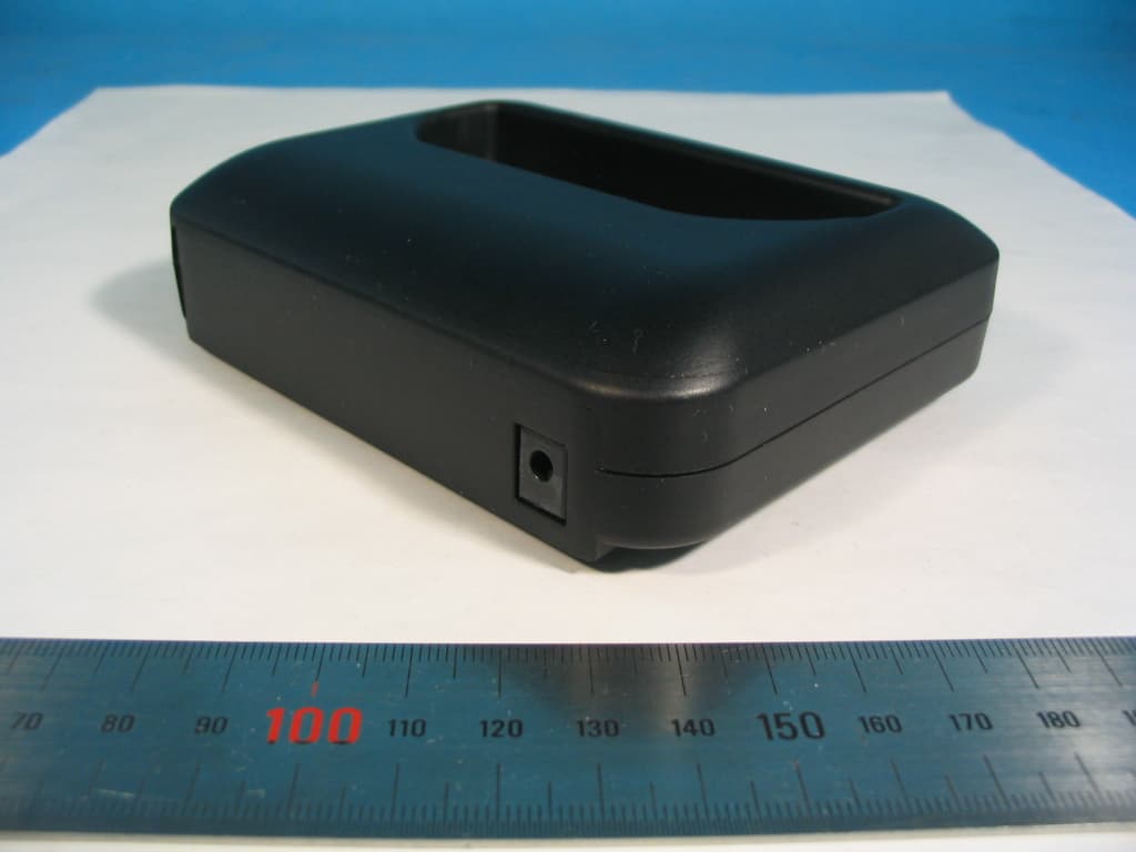
Click to zoom
Application Details
- Equipment Class
- DTS - Digital Transmission System
- Date of Grant
- Mar 19, 2006
- Application Purpose
- Original Equipment
- Date of Application
- Mar 19, 2006
- Equipment Note
- Color LCD Touch Screen Universal Remote Control
- Frequency Range
- 2405.00000000 - 2475.00000000
- Company
- Remote Solution Co., Ltd.
- Country
- South Korea
Documents & Files
Document Text
Text extracted from the exhibit documents filed with the FCC. Open a document above to read the original.
Users Manual
- 1 - XTR39 Hand-Held LCD Remote Control Installation Instructions - 2 - INTRODUCTION .................................................................................................................................. 4 XTR39 Overview...................................................................................................................................................................................... 4 XTR39 Features ....................................................................................................................................................................................... 4 Box Contents ............................................................................................................................................................................................ 4 XTR39 Diagram ....................................................................................................................................................................................... 5 Charging Cradle Diagram ...................................................................................................................................................................... 6 PRELIMINARY SETUP......................................................................................................................................................................... 6 Connecting the Battery Pack ................................................................................................................................................................. 6 Charging the XTR39 and Charging Cradle LED Indicator ................................................................................................................... 7 SYSTEM SETUP.................................................................................................................................................................................. 7 Touch-screen Calibration Adjustment................................................................................................................................................... 9 Touch-screen Calibration Test .............................................................................................................................................................. 9 PROGRAMMING SETUP ................................................................................................................... 10 Universal Dragon™ Installation Guide ............................................................................................................................................... 10 Installation........................................................................................................................................................................................... 10 INSTALLING AND CONFIGURING THE Universal Dragon™ SOFTWARE............................................................................. 14 USB Connection ..................................................................................................................................................................................... 14 Starting XTR39 Universal Dragon™ Software................................................................................................................................... 14 Configuring USB Port ........................................................................................................................................................................... 15 Verifying PC to XTR39 Communication ............................................................................................................................................. 15 STARTING A PROJECT ..................................................................................................................................................................... 16 CREATING THE GRAPHICAL USER INTERFACE (GUI) .......................................................................................................... 17 Choosing A Style ................................................................................................................................................................................ 18 Building a Page (Working with GTL’s) ............................................................................................................................................... 18 Placing Source GTL’s............................................................................................................................................................................ 18 Placing Function Button GTL’s............................................................................................................................................................ 18 Inserting Additional Pages for a Single Source ................................................................................................................................... 20 Editing GTL Properties......................................................................................................................................................................... 21 Inserting Labels...................................................................................................................................................................................... 22 LEARNING IR COMMANDS (Creating Palette Files) ..................................................................................................................... 22 - 3 - Built-In IR Code Library ...................................................................................................................................................................... 22 Testing IR Commands in the IR Library ............................................................................................................................................ 23 Learning IR…
Text truncated - open the document above for the full version.
Users Manual
RH60 Color Touch Screen USER MANUAL www.remotesolution.co.kr 01. HOME & BUTTONS............................................................................................................... 2 02. OPERATING Mode & BUTTONS.......................................................................................... 3 03. SETTING MODE & BUTTONS.............................................................................................. 6 04. CONFIGURATION MODE..................................................................................................... 7 05. BRAND SET MODE................................................................................................................ 7 06. LABEL EDIT MODE............................................................................................................... 9 07. MYPICK SETTING MODE................................................................................................... 11 08. LEARNING MODE............................................................................................................... 12 09. IR/RF SELECT MODE.......................................................................................................... 13 10. CALIBRATION MODE......................................................................................................... 13 11. BIORHYTHM........................................................................................................................ 14 12. GAME..................................................................................................................................... 15 13. MEMO.................................................................................................................................... 16 14. ALARM.................................................................................................................................. 16 15. DEFAULT MODE.................................................................................................................. 18 16. USB MODE............................................................................................................................ 19 17. CRADLE MODE.................................................................................................................... 19 1 01. HOME & BUTTONS The following section provides an overview of the button layout. Simply touch the category you would like to explore. The remote’s functions This part of the remote has the most common features used such as power, channel up/down, enter, volume up/down and mute. are grouped by categories. From the home screen you can access every category. Tip: To access home from any category, simply press “Home” on the bottom left hand side of the remote, or press the house icon on the top left hand side of the remote. The following chart gives an overview of the Home icons: Icon Picture Icon Name Function Devices Access TV, CABLE, DVD, DVR, VCR, SAT, AUDIO, CD and TAPE menus. This menu can have more pages (i.e. Devices ½). To see more pages use the scroll wheel. My Pick My Pick allows a user to program macros and configure the remote to meet a his/her exact requirements; This category includes all the My Pick functions. Others Here you can access GAME, MEMO, ALARM and BIORHYTHM. Setting Here you can access: CONFIGURATION, MYPICK, BRAND SET, IR/RF, LEARN, LABEL, CALIBRATE, DEFAULT 2 If you press Devices, My Pick, Others or Setting from the Home menu you will see: Devices Se My pick Others tting 02. OPERATING Mode & BUTTONS The color touch screen remote is very easy to use; this section will provide an overview of the buttons available. Example 1 From the Home menu press And you will see the screen above. You can now press the icon of the device you wish to operate. Example 2 From the Home menu press And you will see the screen above. You can now press the icon of the device you wish to operate. 3 Icon Picture Icon Name Function Home Access to home screen or IR output Display. Devices (Device Selected) Device selected will be displayed. (i.e. TV) you will also see the following info: Device Name, Current page/Total page (i.e. 1/4) My Pick (Device Selected) MYPICK device selected will be displayed. (i.e. My AUDIO) you will also see the following info: Device Name, Current page/Total page (i.e. 1/6) Mode Exchange My Pick or Device Transfer Device Link Press a button in this menu and you will be able to link a device (by clicking the desired device) to the device mode button. The procedure is: 1.Press one of the four buttons in the menu 2. Select the device you want to link (i.e. My Audio) and press its button. You will now see a change in the device link menu to reflect the new device selected. Device Mode Once you have a device linked (max 4 using a unique button for each device), use one of these 4 buttons to quickly access that device. Scroll-Wheel Use the scroll-wheel to move to a previous page or next page while in operation mode. In addition, use the scroll-wheel to fill out numerical values. To access a device: Ex 1). From the Home menu, Press and then press or press button under the device you wish to select. You can move to the next or previous page of the device using the scroll-wheel. If you want to change a device that is linked, press the button of the device you wish to change and select the new device you wish link. 4 Ex2) How to change a device that is linked; in this example we will change the link from DVR to SAT: In this case we want to change DVR and our DVR screen looks like this: 1. To change a device that is linked, press the button of the device you wish to change (in this case we are changing DVR) 2. Next press the desired device (in this case SAT) 3. Note the change in the device link menu. You can now quickly access that device by pressing the button 5 03. SETTING MODE & BUTTONS From the Home menu press Set-up: Date, time, contrast, backlight, LCD off time, RF ID code and Beep S…
Text truncated - open the document above for the full version.
Cover Letter(s)
Remote Solution Co., Ltd. 92, Chogokri, Nammyun, Kimchon city, Kyungbuk, 740-871,Korea Tel : +82-54-420-4517 Fax : +82-54-420-4530 Chief, Equipment Approval Services Federal Communications Commission PO Box 358315 Pittsburg, PA 15251-5315 Kimchon, February 24, 2006 Authorization Letter Dear Sir or Madam: We, Remote Solution Co., Ltd. hereby authorize O.N.R Tech Inc. 463-49, Sillim-dong, Gwanak-gu, Seoul,151-010, Republic of Korea. To act as our agent and to process and sign on our behalf for equipment authorization under FCC Part 15, Subpart C. This authorization is applicable for the product: RH60A and XTR39 with FCC ID: TX4RH60A Sincerely, Signature : Printed Name: Byung-Chul, Kim Title : Manager Company Stamp:
Cover Letter(s)
Remote Solution Co., Ltd. 92, Chogokri, Nammyun, Kimchon city, Kyungbuk, 740-871,Korea Tel : +82-54-420-4517 Fax : +82-54-420-4530 Federal Communications Commission Authorization and Evaluation Division 7435 Oakland Mills Road Columbia, MD 21046 Kimchon, February 24, 2006 REQUEST FOR CONFIDENTIALITY, FCC ID: TX4RH60A Pursuant to Sections 0.457(d)(1)(ii) and 0.459 of the Commission's Rules, the Applicant hereby requests confidential treatment of information accompanying as outlined below: • Schematic drawing • Bill of Materials • Block Diagram The above materials contain trade secrets and proprietary information not customarily released to the public. Public disclosure of these matters might be harmful to the Applicant and provide unjustified benefits to its competitors. The Applicant understands that pursuant to Rule 0.457(d)(1)(ii), disclosure of this Application and accompanying documentation will not be made before the date of the Grant for this application. Sincerely, Signature : Printed Name: Byung-Chul, Kim Title : Manager Company Stamp:
External Photos
External photos Remote Solution Co., Ltd. Revision No : 1.1 Page: 1 of 1 * External view (XTR39) 1. Front side 2. Right side view External photos Remote Solution Co., Ltd. Revision No : 1.1 Page: 2 of 2 3. Rear side 4. Left side view External photos Remote Solution Co., Ltd. Revision No : 1.1 Page: 3 of 3 * External view (RH60A) 5. Front side 6. Right side view External photos Remote Solution Co., Ltd. Revision No : 1.1 Page: 4 of 4 7. Rear side 8. Left side view External photos Remote Solution Co., Ltd. Revision No : 1.1 Page: 5 of 5 * External view (Cradle) 9. Front side 10. Right side view External photos Remote Solution Co., Ltd. Revision No : 1.1 Page: 6 of 6 11. Rear side 12. Left side View
ID Label/Location Info
RH60A FCC Label and Location FCC Label and Location main FCC Label main Label Position 35mm 60mm RH60 FCC Label and Location FCC Label and Location Cradle FCC Label Cradle Label Position 50mm 30mm XTR39 FCC Label and Location FCC Label and Location main FCC Label main Label Position 35mm 60mm XTR39 FCC Label and Location FCC Label and Location Cradle FCC Label Cradle Label Position 50mm 30mm
Internal Photos
Internal photos Remote Solution Co., Ltd. Revision No : 1.1 Page: 1 of 1 * Internal view (RH60A and XTR39) 1. Internal (Front) 2. Internal ( Rear ) Internal photos Remote Solution Co., Ltd. Revision No : 1.1 Page: 2 of 2 3. Top View of Main PCB ( Zigbee module with a shield case) 4. Top View of Main PCB ( Zigbee module without a shield case) Zigbee Module Zigbee Antenna Zigbee Module Zigbee Antenna RH60A Only (EL Backlight Part) Internal photos Remote Solution Co., Ltd. Revision No : 1.1 Page: 3 of 3 5. Bottom View of Main PCB (Without U11 IC ) 6. Bottom View of Main PCB (With U11 IC ) Zigbee X-tal 2 Zigbee X-tal 1 XTR39 Only (UEI Part) XTR39 Only (UEI Part) Internal photos Remote Solution Co., Ltd. Revision No : 1.1 Page: 4 of 4 7. TOP View of Key & Wheel PCB 8. Bottom View of Key & Wheel PCB
Internal Photos
Internal photos Remote Solution Co., Ltd. Revision No : 1.1 Page: 5 of 5 9. Top View of LCD Module 10. Bottom View of LCD Module Internal photos Remote Solution Co., Ltd. Revision No : 1.1 Page: 6 of 6 11. Top View of Cradle PCB 12. Bottom View of Cradle PCB Internal photos Remote Solution Co., Ltd. Revision No : 1.1 Page: 7 of 7 13. Top Side for Battery PCB 14. Bottom Side for Battery PCB
Operational Description
EUT Description Remote Solution Co., Ltd Ver 1.0 1/1 1. Description. The RH60A and XTR39 is designed to control various home appliances and sensor equipment safely and easily. Using 3.9" full color touch screen makes everyone use easily the product and allows to redesign and recompose the control button according to the uses of each user. The control system for the appliances is the infrared, and the 2.4GHz Zigbee is available as well. The RH60 is designed to control all home appliances with only the 2.4GHz RF by using the Zigbee to IR converter instead of using the infrared, which solve the distance and space problem caused by using the infrared. There are various entertainment features. The alarm, clock, bio-rhythm, memo pad and game are supported. With the manager program, the database and firmware are upgraded and the LCD screen and button are recomposed simply via USB. It is possible to use the product for around 100 hours without charging because of the excellent power management and the high capacity rechargeable battery. While the RH60 is sitting on the charging cradle, the appliances control is allowed in case of using its sub-remote. 2. Feature Type Transmitter Receiver FCC Classification Direct Sequence Spread Spectrum(DSSS) Direct Sequence Spread Spectrum(DSSS) EUT Type Zigbee (802.15.4) Zigbee (802.15.4) Modulation Type OQPSK OQPSK Operating frequency range 2405 – 2475 MHz 2405 – 2475 MHz Bands of operation 2.400 – 2.4835 GHz 2.400 – 2.4835 GHz Number of Channels 15 15 Channel Separation 5MHz 5MHz Type of Antenna Dielectric Chip Antenna Dielectric Chip Antenna Power Supply DC 3.7 V Lithium Ion DC 3.7 V Lithium Ion
Test Report
REPORT NO : NF-TA-R060006 NEX1 Future Co., Ltd. Revision No : 1.2 Page: 1 of 1 FCC TEST REPORT February 27, 2006 NEX 1 Future Co., Ltd. REPORT NO : NF-TA-R060006 NEX1 Future Co., Ltd. Revision No : 1.2 Page: 2 of 2 TEST REPORT CERTIFICATION Applicant : Remote Solution Co., Ltd. Adderss : 92, Chogokri, Nammyun, Kimchon city, Kyungbuk, 740-871, Korea EUT Name : Color LCD Touch screen universal remote control Model No. : RH60A and XTR39 Serial No. : Engineering Sample FCCID : TX4RH60A Testing location : Nex1 Future Co., Ltd. 133, Kongdan-Dong, Gumi-City, Kyeongsangbuk-Do, 730-030, R.O.K Applied specification : FCC Part 15 Test result : The above mentioned test item passed. Test Date February 27, 2006 Review Date February 27, 2006 Tested by Hyo-Jeung, Cho Reviewed by Jeong-Hi, Jin Title Engineer Title EMC Manager Signature Signature I HEREBY CERTIFY THAT the data shown in this report were made in accordance with the procedures given in the applied specification and I assume full responsibility for accuracy and completeness of these data. Note : This test report relates to the a. m. test item. Without permission of the test center this test report is not permitted to be duplicated in extracts. This test report does not entitle to carry any test mark on this or similar products. REPORT NO : NF-TA-R060006 NEX1 Future Co., Ltd. Revision No : 1.2 Page: 3 of 3 Contents 1. GENERAL INFORMATION................................................................................................. 5 1.1 PRODUCT DESCRIPTION............................................................................................... 5 1.2 PROJECT DATA............................................................................................................ 5 1.3 APPLICANT................................................................................................................. 5 1.4 MANUFACTURER......................................................................................................... 5 2. EUT INFORMATION........................................................................................................ 6 2.1 GENERAL EUT INFORMATION....................................................................................... 6 2.2 CENTER FREQUENCY OF TESTED CHANNEL................................................................... 6 2.3 TEST ENVIRONMENT.................................................................................................... 6 2.4 ACCESSORIES AND ANCILLARY EQUIPMENT.................................................................. 6 3. TESTING FACILITIES....................................................................................................... 7 4. EUT DESCRIPTION AND OPERATIONAL DESCRIPTION....................................................... 7 5. TEST SET-UP................................................................................................................. 8 5.1 PRINCIPLE OF CONFIGURATION..................................................................................... 8 5.2 OPERATIONAL MODES................................................................................................. 8 5.3 APPLIED SPECIFICATION.............................................................................................. 8 6. TEST REPORT SUMMARY............................................................................................... 9 7. TEST RESULTS............................................................................................................ 10 7.1 ANTENNA CONNECTOR REQUIREMENTS...................................................................... 10 7.2 AC CONNECTED EMISSION........................................................................................ 11 7.3 6DB BANDWIDTH....................................................................................................... 14 7.4 POWER SPECTRAL DENSITY....................................................................................... 18 7.5 PEAK OUTPUT POWER............................................................................................... 22 7.6 BAND-EDGE COMPLIANCE.......................................................................................... 26 7.7 SPURIOUS CONDUCTED EMISSIONS............................................................................. 30 7.8 SPURIOUS RADIATED EMISSIONS................................................................................ 41 REPORT NO : NF-TA-R060006 NEX1 Future Co., Ltd. Revision No : 1.2 Page: 4 of 4 8. LIST OF TEST AND MEASUREMENT INSTRUMENTS.......................................................... 44 9. NOTES........................................................................................................................ 45 REPORT NO : NF-TA-R060006 NEX1 Future Co., Ltd. Revision No : 1.2 Page: 5 of 5 1. General Information 1.1 Product Description Product Name : Color LCD Touch screen universal remote control Product ID : RH60A and XTR39 Serial No. : Prototype FCC ID : TX4RH60A 1.2 Project data Receipt of EUT : February 13, 2006 Date of Test : February 27, 2006 Data of report : February 27, 2006 1.3 Applicant Company Name : Remote Solution Co., Ltd. Address : 92, Chogokri, Nammyun, Kimchon city, Kyungbuk, 740-871, Korea Contact Person : Mr. Byung-Cheol, Kim 1.4 Manufacturer Company Name : Remote Solution Co., Ltd. Address : 92, Chogokri, Nammyun, Kimchon city, Kyungbuk, 740-871, Korea Contact Person : Mr. Byung-Cheol, Kim REPORT NO : NF-TA-R060006 NEX1 Future Co., Ltd. Revision No : 1.2 Page: 6 of 6 2. EUT Information 2.1 General EUT Information Type Transmitter Receiver FCC Classification Direct Sequence Spread Spectrum(DSSS) Direct Sequence Spread Spectrum(DSSS) EUT Type Zigbee (802.15.4) Zigbee (802.15.4) Modulation Type OQPSK OQPSK Operating frequency range 2405 – 2475 MHz 2405 – 2475 MHz Bands of operation 2.400 – 2.4835 GHz 2.400 – 2.4835 GHz Number of Channels 15 15 Channel Separation 5MHz 5…
Text truncated - open the document above for the full version.
Test Setup Photos
Test setup photos Remote Solution Co., Ltd. Revision No : 1.0 Page: 1 of 1 * Test set-up 1. Radiated Set up Test setup photos Remote Solution Co., Ltd. Revision No : 1.0 Page: 2 of 2 2 Spurious Radiated Emissions 2.1 Radiated test ( 30 MHz ~ 1GHz ) Test setup photos Remote Solution Co., Ltd. Revision No : 1.0 Page: 3 of 3 2.2 Radiated test ( 1 GHz ~ 13GHz ) Test setup photos Remote Solution Co., Ltd. Revision No : 1.0 Page: 4 of 4 2.3 Radiated test ( 13 GHz ~ 18GHz ) Test setup photos Remote Solution Co., Ltd. Revision No : 1.0 Page: 5 of 5 2.4 Radiated test ( 18 GHz ~ 25GHz )
Contact Information
Applicant
Byung-Cheol Kim(Manager)
Test Firm
LIG Nex1 Co., Ltd.Hyo-Jeung Cho
Technical Specifications
| # | Rule Parts | Frequency Range | Power Output |
|---|---|---|---|
| 1 | 15C | 2.40 GHz - 2.48 GHz | 90.00 µW |
Other Applications from Remote Solution Co., Ltd.
TX4-EE48
Mar 24, 2026Josh Edge Base
Equipment Class
DCD - Part 15 Low Power Transmitter Below 1705 kHzTX4-RE47
Mar 12, 2026Josh Edge Remote
Equipment Class
DTS - Digital Transmission SystemTX4-RE79
Jan 22, 2026Remote controller
Equipment Class
DTS - Digital Transmission SystemTX4-RE78
Jan 22, 2026Remote controller
Equipment Class
DTS - Digital Transmission SystemTX4-RE72
Nov 26, 2025Remote control Unit
Equipment Class
DTS - Digital Transmission System