TY3-RST2V2Remote Sensor/Transmitter
Kinectrics, Inc.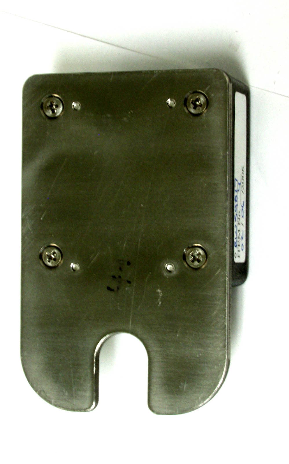
Click to zoom
Application Details
- Equipment Class
- DXX - Part 15 Low Power Communication Device Transmitter
- Date of Grant
- May 01, 2006
- Application Purpose
- Original Equipment
- Date of Application
- May 01, 2006
- Equipment Note
- Remote Sensor/Transmitter
- Frequency Range
- 916.50000000 - 916.50000000
- Company
- Kinectrics, Inc.
- Country
- Canada
Documents & Files
Document Text
Text extracted from the exhibit documents filed with the FCC. Open a document above to read the original.
Users Manual
User’s Guide Revisions and Modifications October 2005 Introduction and Overview The remote monitoring system uses wireless technologies for monitoring temperatures on parts of power system equipment. The system consists of battery-powered remote sensor/transmitters (RST), a ground-based receiver for collecting the data from the sensors (Ground station Collector - GSC) and a data collection computer which collects the data from one or more GSC and makes it available for viewing and other purposes. Experience gained with the first pilot installations led to the development of a second prototype – with incremental improvements over the original system. The second prototype was intended to expand the scope of the trial installation and, at the same time, address some of the issues identified with the initial installation. Specifically, the changes and improvements are as follows: • Redesigned RST layout to facilitate assembly and improve reliability (from assembly-related issues) • New RST is now configurable to emit RF signals constantly, for the purposes of evaluating signal strength for optimal placement of components • Improved antenna performance based on as-assembled conditions • Additional hardware in the GSC to permit signal strength measurements • Modified firmware in the GSC to permit recording of signal strength. Firmware is compatible with old (1 st generation) GSC, except that “zeros” will be recorded in place of signal strength • Simplifed version of the GSC in a handheld configuration for evaluating the received RF signal strength from individual RSTs • Improved communications software for the data collection computer, and improvements to the corresponding portions of the GSC firmware to permit more reliable download of data. Remote Monitoring System – 2 nd Generation Instructions Page 2 of 13 The overall function of the various components are identical to the original system and are illustrated in the following figure. Figure 1 – System overview RST Computer GSC RST Remote Sensor/Transmitter installed on Switchgear GSC Ground Station Collector WSL Wireless Serial Link Master “FreeWave” WSL Station building Switchyard RST RST RST RST RST Cell Modem or standard phone line Remote Monitoring System – 2 nd Generation Instructions Page 3 of 13 PART A - Remote Sensors/Transmitters (RST) The 2 nd Generation RSTs are packaged differently than the original version but otherwise operate identically. The internal firmware is identical in the two versions. The normal operation of the two versions is also identical. However, the 2 nd Generation version has some enhancements not present in the first version. The following describes the differences and other specific notes that pertain to the new version. 1. The RSTs are delivered DISABLED by Kinectrics 2. When installing the RST, keep in mind that the antenna is just below the surface of the “black box”. The antenna radiation pattern is provide separately and should be considered during installation and the placement of the receivers (GST) 3. When installing the RST, apply a small quantity of thermal compound to the bottom of the RST plate to ensure good contact between the equipment and sensor. Do not use excessive quantities – a small “dab” to give a thin layer is sufficient. The bolt used to secure the RST should be securely tightened but care should be taken not to deform the RST plate. Wipe clean any excess thermal compound 4. The RSTs each have a series of pins (“header”) exposed along one side of the box (see figure 2). 5. To ENABLE the RST in normal mode • Carefully insert on activation strip into the pins of the header and make sure it is seated firmly – make sure to make note of the correct orientation (figure 2). The activation strip is NOT mechanically keyed but is colour-coded. The grey side should face up. (note that some of the pin positions on the activation strip are not used). • once the activation strip is installed, the RST is active and in NORMAL mode – temperatures on the base plate are measured and broadcast every 15 minutes. • once activated, the activation strip may be sealed with silicone rubber (provided) to prevent ingress of moisture • The RST uses an internal high temp, long-life battery which should last 5-10 years 6. To ENABLE the RST in TEST mode • Carefully insert the test adapter into header by carefully lining up the pins (figure 3). Note that the test adapter should be properly centered and aligned (note that some of the pin positions on the test adapter are not used). • The red LED on the test adapter should illuminate • The RST will continuously broadcast RF at the carrier frequency (50% duty cycle); no data is transmitted • the handheld receiver (HSM) can be now used to evaluate signal strength • while in test mode, the external battery on the test adapter is used – the internal battery is not depleted. The internal battery is a AA-size 3.6V lithium. The battery should have a very long life but can be replaced with special tools, if required. Remote Monitoring System – 2 nd Generation Instructions Page 4 of 13 Figure 2 – 2 nd Generation remote temperature sensor (RST). The location of the ‘header’ is shown on the left. The activation strip (grey side up) should be carefully inserted and seated fully into the header for NORMAL mode operation. The opening can be filled with silicone rubber, if desired. Figure 3 – Test Adapter connected to the RST. Care should be taken in aligning the pins appropriately. The test adapter will be centred and the red LED will illuminate when installed properly. “header” Activation Strip (grey side up) Test adapter Remote Monitoring System – 2 nd Generation Instructions Page 5 of 13 PART B –Ground station collector The 2 nd Generation GSC is identical to the 1 st generation version, except for the addition of some hardware components to permit the measurement of received signal strength and new firmware. Consequently, the new circuit board is slightly larger than the previo…
Text truncated - open the document above for the full version.
Cover Letter(s)
DATE Equipment Authorisation Division Federal Communications Commission 7435 Oakland Mills Road Columbia, MD 21046 FCC ID: TY3-RST2V2 Product Name: RST2 – (Remote Sensor Transmitter 2) Request for Confidentiality Pursuant to Sections 0.457 and 0.459 of the commissions rules, we hereby request that the following documents be held confidential: • Schematics – Transmitter Schematic.PDF • Operational Description.doc, • System Block Diagrams.doc These materials contain trade secrets and proprietary information and are not customarily released to the public. The public disclosure of this information might be harmful to the company and provide unjustified benefits to our competitors. Dated this 8 Day of February 20 06 By: Dr. John Kuffel Signature Printed Title: General Manager On behalf of : Kinectrics, Inc. Telephone: 416-207-6539
Test Report
FCC Part 15 Subpart C, 15.249 : August 2005 Test Report: 6W59817 Applicant: Kinectrics Inc 800 Kipling Ave. Toronto, Ontario M8Z 6C4 Canada Apparatus: Remote Sensor/Transmitter (RST2) FCC ID: TY3-RST2V2 In Accordance With: FCC Part 15 Subpart C, 15.249 Operation in the 902-928MHz, 2400 - 2483.5 MHz, 5725-5850MHz and 24.0-24.25 GHz Tested By: Nemko Canada Inc. 303 River Road Ottawa, Ontario K1V 1H2 Authorized By: Roman Kuleba, EMC Specialist Date: April 12, 2006 Total Number of Pages: 16 Nemko Canada Inc. REPORT SUMMARY Report Number: 6W59817 FCC ID: TY3-RST2V2 Specification: FCC Part 15 Subpart C, 15.249 Page 2 of 16 Report Summary These tests were conducted on a sample of the equipment for the purpose of demonstrating compliance with Part 15, Subpart C. Radiated tests were conducted in accordance with ANSI C63.4-2003. Radiated emissions are made on an open area test site. A description of the test facility is on file with the FCC. The assessment summary is as follows: Apparatus Assessed: Remote Sensor/Transmitter (RST2) Specification: FCC Part 15 Subpart C, 15.249 Compliance Status: Complies Exclusions: None Non-compliances: None Report Release History: Original Release Author: Mac Huang, EMC Specialist Note that the results contained in this report relate only to the items tested and were obtained in the period between the date of initial receipt of samples and the date of issue of the report. This test report has been completed in accordance with the requirements of ISO/IEC 17025. Nemko Canada Inc. authorizes the applicant to reproduce this report provided it is reproduced in its entirety and for use by the company’s employees only. Any use which a third party makes of this report, or any reliance on or decisions to be made based on it, are the responsibility of such third parties. Nemko Canada Inc. accepts no responsibility for damages, if any, suffered by any third party as a result of decisions made or actions based on this report. Nemko Canada Inc. REPORT SUMMARY Report Number: 6W59817 FCC ID: TY3-RST2V2 Specification: FCC Part 15 Subpart C, 15.249 Page 3 of 16 TABLE OF CONTENTS Report Summary......................................................................................................................................... 2 Section 1 : Equipment Under Test............................................................................................................. 4 1.1 Product Identification .................................................................................................................................4 1.2 Samples Submitted for Assessment............................................................................................................4 1.3 Theory of Operation ...................................................................................................................................4 1.4 Technical Specifications of the EUT ..........................................................................................................5 1.5 Block Diagram of the EUT.........................................................................................................................5 Section 2 : Test Conditions......................................................................................................................... 6 2.1 Specifications .............................................................................................................................................6 2.2 Deviations From Laboratory Test Procedures ............................................................................................6 2.3 Test Environment .......................................................................................................................................6 2.4 Test Equipment...........................................................................................................................................6 Section 3 : Observations ............................................................................................................................. 7 3.1 Modifications Performed During Assessment ............................................................................................7 3.2 Record Of Technical Judgements ...............................................................................................................7 3.3 EUT Parameters Affecting Compliance .....................................................................................................7 3.4 Test Deleted................................................................................................................................................7 3.5 Additional Observations .............................................................................................................................7 Section 4 : Results Summary ..................................................................................................................... 8 4.1 FCC Part 15 Subpart C : Test Results ........................................................................................................9 Appendix A : Test Results ........................................................................................................................ 10 Clause 15.209(a) Radiated Emissions within Restricted Bands ..........................................................................10 Clause 15.249(d) Spurious emissions (except Harmonics)..................................................................................14 Appendix B : Setup Photographs ............................................................................................................ 15 Appendix C : Block Diagram of Test Setups .......................................................................................... 16 Nemko Canada Inc. SECTION 1 : EQUIPMENT UNDER TEST Report Number: 6W59817 FCC ID: TY3-RST2V2 Specification: FCC Part 15 Subpart C, 15.249 Page 4 of…
Text truncated - open the document above for the full version.
Test Setup Photos
Appendix B : Setup Photographs Spurious Emissions Setup:
Contact Information
Applicant
Silvano Rizzetto(Mr.)
Technical Contact
Non-Technical Contact
Nemko CanadaDebbie Millar
[email protected]613 737 9680
Test Firm
Nemko Canada Inc. (Ottawa)Charles Neal
Technical Specifications
| # | Rule Parts | Frequency Range | Power Output |
|---|---|---|---|
| 1 | 15C | 916.5 MHz - 916.5 MHz | - |
Other Applications from Kinectrics, Inc.
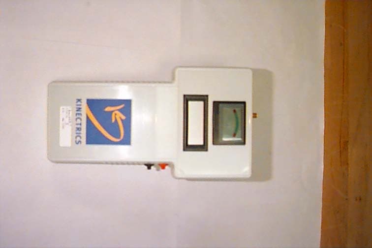
TY3-HSMV1
Apr 03, 2006Handheld Signal Strenght Meter
Equipment Class
CYY - Communications Receiver used w/Pt 15 Transmitter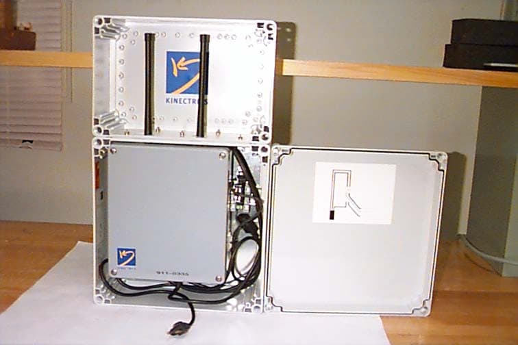
TY3-GSCV3
Apr 03, 2006Ground Station Controller
Equipment Class
CYY - Communications Receiver used w/Pt 15 Transmitter