TYD37920Emergency Wall Communicator
LogicMark, Inc.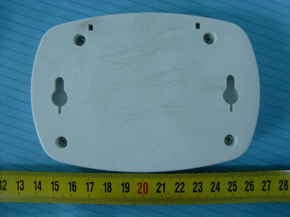
Click to zoom
Application Details
- Equipment Class
- PUB - Part 15 Unlicensed PCS Base Station
- Date of Grant
- Sep 14, 2010
- Application Purpose
- Original Equipment
- Date of Application
- Sep 14, 2010
- Equipment Note
- Emergency Wall Communicator
- Frequency Range
- 1921.53600000 - 1928.44800000
- Company
- LogicMark, Inc.
- Country
- United States
Documents & Files
Document Text
Text extracted from the exhibit documents filed with the FCC. Open a document above to read the original.
Users Manual
v0.2 Guardian Alert English SET UP INSTRUCTIONS Emergency Wall Communicator Model #37920 This accessory is to be used with the LogicMark’s DECT line of Personal Emergency Response Systems. This includes the FreedomAlert and the LifeSentry product line. Up to a total of 4 pendants and Emergency Wall Communicators (EWC) can be learned to one LogicMark “DECT” (1.9 Ghz) base unit. CONTENTS: Emergency Wall Communicator (EWC) AAA Alkaline Batteries 4 pieces Double Stick Velcro Screwdriver 2 Screws 2 Emergency Wall Communicator v0.2 TABLE OF CONTENTS Installing the Batteries ..............................................................................3 Learning the EWC to the Base of Your PERS System ..........................3 Battery Check ............................................................................................4 System Check ............................................................................................5 Warranty ....................................................................................................7 Product Specifications ..............................................................................8 NOTE: Before programming this Emergency Wall Communicator (EWC) to work with your LogicMark DECT base unit, you must acknowledge that all of the Warnings, Limitations of Liability, Disclaimers, FCC information and Testing Instructions written in the LogicMark Personal Emergency Response System (PERS) instruction manuals pertain to the use of this EWC as well when used with these products. By programming this EWC to your LogicMark PERS product, you acknowledge that you have a copy of these instructions and have read them. If you do not have a copy, you can always download one off of our website or by calling our company and requesting one. v0.2 Emergency Wall Communicator 3 Installing the Battery Use the supplied screwdriver to unscrew the battery compartment. Install the 4 AAA alkaline batteries - alternating them as they are installed. Note the polarity on the inside of the battery cover. The spring contacts are meant to touch the negative side of the batteries. Close the battery cover using the screwdriver provided. Learning the EWC to the Base unit of Your PERS System. Note: Throughout this manual - EWC will refer to the Emergency Wall Communicator; Pendant will refer to a hand-held pendant used by the Personal Emergency Response System (PERS) - and Base will refer to the base unit of the PERS system. On the Base Unit: 1. Push and release the RED Code Learn button on the back of the Base unit. (Use the tip of the screwdriver or a ball-point pen to reach through the case). You will hear a voice prompt “Pendant Learning” On the EWC: 2. PUSH the Gray Battery Test button and the RED Emergency button simultaneously –HOLD both buttons for a few seconds until you hear “Pendant Learning” from the EWC - then release both buttons. • If “Base and Pendant out of Range” is heard from the EWC, stop - wait 30 seconds and start at step #1 again. 3. When Pendant learning has been successful you will hear “All Systems are OK” and then it will announce the mode of the Base unit. TABLE OF CONTENTS Installing the Batteries ..............................................................................3 Learning the EWC to the Base of Your PERS System ..........................3 Battery Check ............................................................................................4 System Check ............................................................................................5 Warranty ....................................................................................................7 Product Specifications ..............................................................................8 4 Emergency Wall Communicator v0.2 Notes: • You have up to 45 seconds after pushing the RED Code Learn button on the Base unit to get the EWC to enter “Pendant Learning”. • Learning additional Pendants or EWCs does not erase previously learned Pendants or EWCs. • The Base unit will automatically exit the Pendant learning mode after several seconds or if Pendant learning failed. • Only a combined total of 4 Pendants and EWCs can be learned to a Base unit. If a Pendant has been lost or replaced, erase all the Pendants and relearn all current Pendants and EWCs. (See next paragraph). At a later point in time, you might want to erase your previously learned pendants. You can erase all previously learned Pendants or EWCs by simply holding down the red Code Learn button at the back of the Base unit for 8 seconds. You will hear the confirmation of “Previous Pendant Codes Erased” from the Base unit. After that, you can program a new Pendant to the Base unit following the steps above as desired. Mounting the Product. You have two choices to mount the product to the wall. You can use the two screws provided - or you can use the special Velcro style fastener provided. If using the screws - locate the screws exactly 3 and 1/8 inches apart on the wall. If using the Velcro - make sure the surfaces are clean and dry before mounting. Battery Check: The 4 AAA alkaline batteries should power the unit for over one year in standby mode. When the EWC is used - there are several hours of talk time on fresh batteries. We recommend replacement of the batteries every 6 monhts, just like a smoke detector. However, the EWC has a built-in battery tester to allow you easy confirma- tion of the status of the batteries. When you press the small Gray button v0.2 Emergency Wall Communicator 5 on the EWC, a voice announcement will inform you of the condition of the battery. One of the following messages will be heard: “Battery is ok.” Check the battery condition monthly. “Battery is low.” The batteries should be replaced within the next weeks. “Replace battery now.” The 4 AAA batteries should be replaced now with 4 new AAA alkaline batteries. Please note: If there is no response after pressing the button for…
Text truncated - open the document above for the full version.
External Photos
EXHIBIT B - EUT EXTERNAL PHOTOGRAPHS EUT –TopView EUT – Bottom View
ID Label/Location Info
EXHIBIT A - FCC ID LABELING AND LOCATION FCC ID Label FCC ID Label Location Label here The label shown shall be permanently affixed at a conspicuous location on the device and be readily visible to the user at the time purchase (Labeling requirements per 2.925)
Internal Photos
EXHIBIT C - EUT INTERNAL PHOTOGRAPHS EUT – Battery Cover off View EUT – Cover off View EUT – Main Board Top View EUT – Main Board Shielding off View EUT – Main Board Bottom View Antenna Locatiion
RF Exposure Info
LogicMark, LLC FCC ID: TYD37920 Report #: RSZ10071604 Page 9 of 46 FCC Part 15D Test Report FCC §15.319 (i) & §2.1091 - RF EXPOSURE Applicable Standard According to FCC Part 15.319 (i), Unlicensed PCS devices are subject to the radiofrequency radiation exposure requirements specified inFCC§1.1307(b) and FCC§2.1091 of this chapter, as appropriate. All equipment shall be considered to operate in a “general population/uncontrolled” environment. Applications for equipment authorization of devices operating under this section must contain a statement confirming compliance with these requirements for both fundamental emissions and unwanted emissions. Technical information showing the basis for this statement must be submitted to the Commission upon request. Limits for Maximum Permissible Exposure (MPE) (§1.1310, §2.1091) Limits for General Population/Uncontrolled Exposure Frequency Range (MHz) Electric Field Strength (V/m) Magnetic Field Strength (A/m) Power Density (mW/cm 2 ) Averaging Time (minutes) 0.3–1.34 614 1.63 *(100) 30 1.34–30 824/f 2.19/f *(180/f²) 30 30–300 27.5 0.073 0.2 30 300–1500 / / f/1500 30 1500–100,000 / / 1.0 30 f = frequency in MHz; * = Plane-wave equivalent power density; According to §1.1310 and §2.1091 RF exposure is calculated. MPE Predication Predication of MPE at a given distance S = PG/4πR² Where: S= power density (in appropriate units, e.g. mW/cm 2 ); P = power input to the antenna (in appropriate units, e.g., mW); G =gain of the antenna in the direction of interest relative to an isotropic radiator, the gain is normally numeric gain; R = distance to the center of radiation of the antenna (appropriate units, e.g., cm) Antenna Gain Conducted Power Frequency (MHz) (dBi) (numeric) (dBm)(mW) Evaluation Distance (cm) Power Density (mW/cm 2 ) MPE Limit (mW/cm 2 ) 1928.448 2.14 1.64 18.6873.79mW20 0.024 1.0 Result: Compliant
Test Report
Note: This test report is prepared for the customer shown above and for the device described herein. It may not be duplicated or used in part without prior written consent from Bay Area Compliance Laboratories Corp. (Shenzhen).This report must not be used by the customer to claim product certification, approval, or endorsement by NVLAP*, NIST, or any agency of the Federal Government. * This report may contain data that are not covered by the NVLAP accreditation and are marked with an asterisk “*” (Rev.2) FCC PART 15D MEASUREMENT AND TEST REPORT For LogicMark, LLC 8625 Hampton Way; Fairfax Station, Virginia 22039, USA FCC ID: TYD37920 Report Type: Original Report Product Type: Emergency Wall Communicator Test Engineer: Felix Li Report Number: RSZ10071604 Report Date: 2010-08-30 Reviewed By: Merry Zhao EMC Engineer Prepared By: Bay Area Compliance Laboratories Corp. (Shenzhen) 6/F, the 3rd Phase of WanLi Industrial Building, ShiHua Road, FuTian Free Trade Zone Shenzhen, Guangdong, China Tel: +86-755-33320018 Fax: +86-755-33320008 LogicMark, LLC FCC ID: TYD37920 Report #: RSZ10071604 Page 2 of 46 FCC Part 15D Test Report TABLE OF CONTENTS GENERAL INFORMATION...................................................................................................................................... 4 PRODUCT DESCRIPTION FOR EQUIPMENT UNDER TEST (EUT).................................................................................... 4 OBJECTIVE.................................................................................................................................................................. 4 RELATED SUBMITTAL(S)/GRANT(S) ............................................................................................................................ 4 TEST METHODOLOGY.................................................................................................................................................. 4 TEST FACILITY............................................................................................................................................................ 4 SYSTEM TEST CONFIGURATION ......................................................................................................................... 6 DESCRIPTION OF TEST CONFIGURATION...................................................................................................................... 6 EQUIPMENT MODIFICATIONS...................................................................................................................................... 6 LOCAL SUPPORT EQUIPMENT LIST AND DETAILS........................................................................................................ 6 CONFIGURATION OF TEST SETUP................................................................................................................................. 6 BLOCK DIAGRAM OF TEST SETUP...............................................................................................................................7 SUMMARY OF TEST RESULTS.............................................................................................................................. 8 FCC §15.319 (I) & §2.1091 - RF EXPOSURE............................................................................................................ 9 APPLICABLE STANDARD.............................................................................................................................................. 9 FCC §15.317 & §15.203 - ANTENNA REQUIREMENT........................................................................................ 10 APPLICABLE STANDARD............................................................................................................................................ 10 FCC §15.319 (E) - ANTENNA GAIN........................................................................................................................ 11 APPLICABLE STANDARD............................................................................................................................................ 11 FCC §15.323 (A) - EMISSION BANDWIDTH ........................................................................................................ 12 APPLICABLE STANDARD............................................................................................................................................ 12 TEST EQUIPMENT LIST AND DETAILS........................................................................................................................ 12 TEST PROCEDURE...................................................................................................................................................... 12 TEST DATA................................................................................................................................................................ 13 FCC §15.319 (C) - PEAK TRANSMIT POWER ..................................................................................................... 15 APPLICABLE STANDARD............................................................................................................................................ 15 TEST PROCEDURE...................................................................................................................................................... 15 TEST EQUIPMENT LIST AND DETAILS........................................................................................................................ 15 TEST DATA................................................................................................................................................................ 16 FCC §15.319 (D) - POWER SPECTRAL DENSITY............................................................................................... 18 APPLICABLE STANDARD..................................................................................................................…
Text truncated - open the document above for the full version.
Test Setup Photos
EXHIBIT D - TEST SETUP PHOTOGRAPHS Radiated Emissions - Front View (30 MHz-1000 MHz) Radiated Emissions - Side View (30 MHz-1000MHz) Radiated Emissions - Front View (Above 1 GHz) Radiated Emissions - Rear View (Above 1 GHz) Frequency Stability
Contact Information
Applicant
John Augustine Federico(Senior Director, Product)
Test Firm
Bay Area Compliance Laboratory Corp. (Shenzhen)John Chan
Technical Specifications
| # | Rule Parts | Frequency Range | Power Output |
|---|---|---|---|
| 1 | 15D | 1.92 GHz - 1.93 GHz | 73.80 mW |
Other Applications from LogicMark, Inc.

TYD-GA40711B
Aug 11, 2020LTE Emergency Mobile Phone
Equipment Class
PCT - PCS Licensed Transmitter worn on body
TYD3091160
Nov 15, 2015Guardian Alert 911
Equipment Class
PUE - Part 15 Unlicensed PCS portable Tx held to ear
TYD-GA30711
Jul 29, 20153G mobile phone only call 911
Equipment Class
JBP - Part 15 Class B Computing Device Peripheral
TYD-CS40914
Jan 16, 2014Caretaker Sentry Base Unit
Equipment Class
PUB - Part 15 Unlicensed PCS Base Station
TYD-CS41920
Jan 05, 2014Caretaker Sentry Emergency Wall Communicator
Equipment Class
PUF - Part 15 Unlicensed PCS portable Tx held to face