TZXRS100RanchSensor
Ranch Systems LLC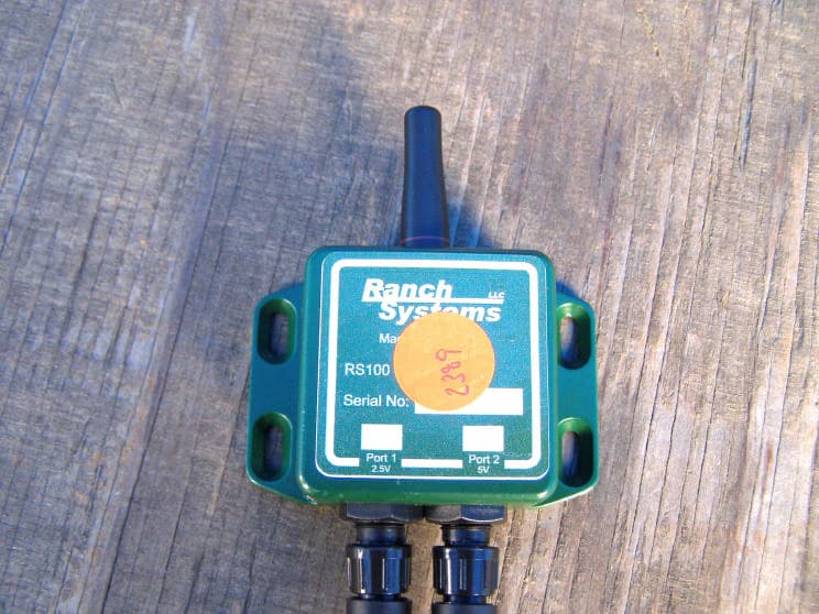
Click to zoom
Application Details
- Equipment Class
- DSC - Part 15 Security/Remote Control Transmitter
- Date of Grant
- Aug 24, 2006
- Application Purpose
- Original Equipment
- Date of Application
- Aug 24, 2006
- Equipment Note
- RanchSensor
- Frequency Range
- 433.92000000 - 433.92000000
- Company
- Ranch Systems LLC
- Country
- United States
Documents & Files
Document Text
Text extracted from the exhibit documents filed with the FCC. Open a document above to read the original.
Users Manual
1 FCC Statement This equipment has been tested and found to comply with the limits for a class B digital device, pursuant to part 15 of the FCC Rules. These limits are designed to provide reasonable protection against harmful interference in a residential installation. This equipment generates, uses, and can radiate radio frequency energy and if not installed and used in accordance with the instructions, may cause harmful interference to radio communications. However, there is no guarantee that interference will not occur in a particular installation. If this equipment does cause harmful interference to radio or television reception, which can be determined by turning the equipment off and on, the user is encouraged to try to correct the interference by one or more of the following measures: • Reorient or relocate the receiving antenna • Increase the separation between the equipment and the receiver • Connect the equipment into an outlet on a circuit different from that to which the receiver is connected • Consult the dealer or an experienced radio/TV technician for help This equipment has been verified to comply with the limits for a class B computing device, pursuant to FCC rules. Operation with non-approved equipment is likely to result in interference to radio and TV reception. The user is cautioned that changes and modifications made to the equipment without the approval of the manufacturer could void the user’s authority to operate this equipment. RanchMaster System Manual 2 WARNING – READ BEFORE USE! Congratulations on choosing the RanchMaster system for your business. We believe that RanchMaster is the most advanced technology available today for agricultural irrigation and climate control. However, it is important to emphasize that this system is still only a tool, and cannot be expected to function error-free, 100% of the time. The following are just some of the risks and limitations that you need to plan for: • Control and Data information is communicated via cellular networks, such as Cingular. These network experience outages, which in turn will prevent the RanchMaster system from working • Sensors occasionally report erroneous values, so ultimately no data value can ever be assumed to be 100% true. Sensor data is a proxy for real conditions in the field, but ultimately you should never take drastic actions before double-checking specific conditions. • Electrically operated valves may malfunction, so for example, the RanchMaster system may report a valve as open when in fact the valve itself is still closed. Correlating to water flow and soil moisture sensors are good ways to detect such problems. • No piece of software is error-free, despite thorough testing. This means that RanchMaster system may perform incorrect and unexpected actions, such as opening a valve without explicit instructions. The user must be vigilant in monitoring such anomalies to avoid loss or damage. RanchMaster sensors can themselves help implement such “closed loop” verification, but it ultimately remains the ranch owner responsibility. 3 Limited Warranty Ranch Systems does not warrant that the RanchMaster solution will operate uninterrupted or error free. Ranch Systems will use commercially reasonable efforts to correct any RanchMaster Solution problems in a timely manner upon identification of issue or receipt of notice. If a customer is dissatisfied with the equipment and service within the first 90 days of equipment installation and activation, they may terminate service. Limited Liability Ranch Systems shall not be liable for direct, indirect, incidental or consequential damages including without limitation damages for harm to business, lost profits or lost revenues (however arising, including negligence), whether or not Ranch Systems has been advised of the possibility of such damages. Ranch Systems shall not be liable for any damage that may arise out of use, or inability to use, the services or products provided hereunder. RanchMaster System Manual 4 RanchMaster System Manual Version 2.1 Copyright © 2006 Ranch Systems LLC All Rights Reserved 5 Table of Contents CHAPTER 1 – GETTING STARTED 7 1.1 Introduction 7 1.2 Features of this manual 7 CHAPTER 2 – ABOUT YOUR SYSTEM 9 2.1 RanchMaster System Overview 9 2.2 Sensor Node Specifications 14 2.3 Base Station Specifications Error! Bookmark not defined. 2.4 Hosted Software Specifications Error! Bookmark not defined. CHAPTER 3 - INSTALLATION 17 3.1 What You Have Received 17 3.2 Base Station Installation 18 3.3 Solar Panel Installation 20 3.4 Sensor Node Installation 20 3.5 Sensor Installation 21 CHAPTER 4 – BASE STATION USAGE 20 4.1 Introduction to manual base station usage 20 4.2 Base station keypad overview 20 4.3 Menu Options 22 CHAPTER 5 – INTERNET SOFTWARE 30 5.1 Logins & Security 30 5.2 Online Features 30 5.3 SMS Commands 46 CHAPTER 6 – TROUBLESHOOTING 46 6.1 Trouble Shooting Overview 46 CHAPTER 7 – CUSTOMER SERVICE 50 RanchMaster System Manual 6 7.1 Customer Service 50 7.2 Contact Information 50 GLOSSARY 51 CONTACT INFORMATION 55 7 Chapter 1 – Getting Started 1.1 Introduction This manual describes the use of the RanchMaster system, including base station, wireless sensor nodes, and corresponding web software. 1.2 Features of this manual This manual contains 7 chapters intended to explain the features and functions of Ranch Systems equipment. Chapter 1 – Getting Started A preview of the manual Chapter 2 – About Your System Overview of RanchMaster system components and technical specifications Chapter 3 – Installation Itemizes your RanchMaster system components and explains the proper methods for setup of each component Chapter 4 – Base Station Software Instructions for the setup and navigation of the RanchMaster base station Chapter 5 – Internet Software RanchMaster System Manual 8 Instructions for the setup and navigation of the Ranch Systems website and how to use it in conjunction with the base station Chapter 6 – Trouble Shooting An explanat…
Text truncated - open the document above for the full version.
Cover Letter(s)
Correspondence by Project Project Number: Correspondence Number Memo TZXRS100-1 1) The test report has a different FCC ID listed then what is listed in the application. Please explain. Response: The Test Report has been Revised to include the correct FCC ID. 2) The test report states that the device was both transmitting and receiving, but no data supporting the receive mode was supplied. Please submit the data for the receive mode. Response: The EUT has no receive mode as the chip (TXM-433-LR-S) is a transmit chip only. The test report has been revised to show this. 3) The operational description submitted does not meet the operational requirements of 15.231(a). Please explain how the device will meet the operational requirements of 15.231(a). Response: The Operational Description has been revised. 4) In the FCC statement located in the User Manual, it mentions that the device was certified to comply with the limits of a class B computing device, which is incorrect. Please correct and send a corrected user manual. Response: The Users Manual has been revised. 5) In the FCC statement located in the User Manual, it mentions that the device requires shielded cables to maintain compliance, which is incorrect. Please correct and send a corrected user manual. Response: The Users Manual has been revised. 1348586678
ID Label/Location Info
1.99” 2.57”
Test Report
Ref Lvl 92 dB V Ref Lvl 92 dB V RBW 1 MHz VBW 1 MHz RF Att 10 dB A I2D Unit dB V P0 TDS SWT 100 ms Center 433.92 MHz10 ms/ 1VIEW1AP 0 10 20 30 40 50 60 70 80 -8 92 1 1 Delta 1 [T1] -0.54 dB 25.250501 ms Date: 29.MAR.2006 14:58:27 Plot Showing the Pulse Train Only shows up once per 100 mS. Ref Lvl 92 dB V Ref Lvl 92 dB V RBW 1 MHz VBW 1 MHz RF Att 10 dB A I2D Unit dB V TRG SWT 15 ms Center 433.92 MHz1.5 ms/ P0 TDS 1VIEW1AP 0 10 20 30 40 50 60 70 80 -8 92 1 1 Delta 1 [T1] -1.17 dB -490.981964 s Date: 29.MAR.2006 15:05:33 Time of Pulse #1 = 490.981964 uS Ref Lvl 92 dB V Ref Lvl 92 dB V RBW 1 MHz VBW 1 MHz RF Att 10 dB A I2D Unit dB V TRG SWT 15 ms Center 433.92 MHz1.5 ms/ P0 TDS 1VIEW1AP 0 10 20 30 40 50 60 70 80 -8 92 1 1 Delta 1 [T1] 3.61 dB 260.521042 s Date: 29.MAR.2006 15:06:21 Time of Pulse #2 = 260.521042 uS Ref Lvl 92 dB V Ref Lvl 92 dB V RBW 1 MHz VBW 1 MHz RF Att 10 dB A I2D Unit dB V TRG SWT 15 ms Center 433.92 MHz1.5 ms/ P0 TDS 1VIEW1AP 0 10 20 30 40 50 60 70 80 -8 92 1 1 Delta 1 [T1] 3.21 dB -1.122244 ms Date: 29.MAR.2006 15:07:30 Time of Pulse #3 = 1.122244 mS Ref Lvl 92 dB V Ref Lvl 92 dB V RBW 1 MHz VBW 1 MHz RF Att 10 dB A I2D Unit dB V TRG SWT 15 ms Center 433.92 MHz1.5 ms/ P0 TDS 1VIEW1AP 0 10 20 30 40 50 60 70 80 -8 92 1 1 Delta 1 [T1] -1.81 dB 1.533066 ms Date: 29.MAR.2006 15:08:30 Time of Pulse #4 = 1.533066 mS Ref Lvl 92 dB V Ref Lvl 92 dB V RBW 1 MHz VBW 1 MHz RF Att 10 dB A I2D Unit dB V TRG SWT 15 ms Center 433.92 MHz1.5 ms/ P0 TDS 1VIEW1AP 0 10 20 30 40 50 60 70 80 -8 92 1 1 Delta 1 [T1] -0.58 dB 901.803607 s Date: 29.MAR.2006 15:09:15 Time of Pulse #5 = 901.803607 uS Ref Lvl 92 dB V Ref Lvl 92 dB V RBW 1 MHz VBW 1 MHz RF Att 10 dB A I2D Unit dB V TRG SWT 15 ms Center 433.92 MHz1.5 ms/ P0 TDS 1VIEW1AP 0 10 20 30 40 50 60 70 80 -8 92 1 1 Delta 1 [T1] 0.72 dB -1.322645 ms Date: 29.MAR.2006 15:13:35 Time of Pulse #6 = 1.322645 mS Ref Lvl 92 dB V Ref Lvl 92 dB V RBW 1 MHz VBW 1 MHz RF Att 10 dB A I2D Unit dB V TRG SWT 15 ms Center 433.92 MHz1.5 ms/ P0 TDS 1VIEW1AP 0 10 20 30 40 50 60 70 80 -8 92 1 1 Delta 1 [T1] -1.87 dB -1.953908 ms Date: 29.MAR.2006 15:16:47 Time of Pulse #7 = 1.953908 mS Ref Lvl 92 dB V Ref Lvl 92 dB V RBW 1 MHz VBW 1 MHz RF Att 10 dB A I2D Unit dB V P0 TDS SWT 35 ms Center 433.92 MHz3.5 ms/ TRG 1VIEW1AP 0 10 20 30 40 50 60 70 80 -8 92 1 1 Delta 1 [T1] 0.61 dB 25.110220 ms Date: 29.MAR.2006 15:03:39 # of #1 Pulses = 2 * 490.981964 uS = 981.9639 uS # of #2 Pulses = 12 * 260.521042 uS = 3.126253 mS # of #3 Pulses = 1 * 1.122244 mS = 1.122244 mS # of #4 Pulses = 1 * 1.533066 mS = 1.533066 mS # of #5 Pulses = 1 * 901.803607 uS = 901.803607 uS # of #6 Pulses = 1 * 1.322645 mS = 1.1322645 mS # of #7 Pulses = 4 * 1.953908 mS = 7.815632 mS Total Time = 16.61323 mS = 16.61323 % Duty Cycle
Contact Information
Applicant
Christopher J Malone(Wireless Technician)
Technical Contact
Compatible Electronics, Inc.Kyle Fujimoto
[email protected]714-579-0500
114 Olinda Drive · Brea, California · United States
Test Firm
Compatible Electronics, Inc.Michael Christensen
Technical Specifications
| # | Rule Parts | Frequency Range | Power Output |
|---|---|---|---|
| 1 | 15.231 | 433.92 MHz - 433.92 MHz | - |