Text extracted from the exhibit documents filed with the FCC. Open a document above to read the original.
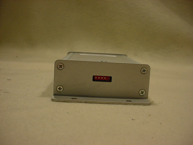
5015 B.U. Bowman Drive Buford, GA 30518 USA Voice: 770-831-8048 Fax: 770-831-8598 FCC Part 15.249 Certification Test Report FCC ID: U22GSESWW FCC Rule Part: 15.249 ACS Report Number: 07-0016-15C Manufacturer: Convia β A Herman Miller Company Model: Wireless Switch Manual Convia tm β A Herman Miller Company ConviaRF Wireless Switch System User Guide March 2007 Convia tm β A Herman Miller Company Components There are two types of components involved in implementing a ConviaRF Wireless Switch System. They are the ConviaRF Wireless Switch and Wireless Switch Coordinator. ConviaRF Wireless Switch (SWW) The Wireless Switch (SWW) can be used in the same way as the wired Convia switch (###). Like the wired switch, the wireless switch can be used to control lights and other devices that are connected to Convia Smart Connectors. Just like the wired switch the user manually presses the up or down switch to turn selected light fixtures on and off. The Wireless Switch It can be programmed to operate a wide configuration of light fixtures and also used to control dimming levels. The Wireless Switch will operate at a minimum of 75 feet from a ConviaRF Wireless Coordinator. Convia tm β A Herman Miller Company ConviaRF Wireless Coordinator (WSC) The Wireless Switch Coordinator (Coordinator) acts as the network interface for the ConviaRF Wireless Switch. It provides a gateway to the ConviaNET communications network and allows ConviaRF Wireless Switch to be an active participant on the network. A key function of the Wireless Switch the Coordinator is that it monitors the ConviaNet communications network for relevant message commands that apply to the Wireless Switch. This allows the Wireless Switch to connect to the network less frequently and increases battery life. ConviaRF Dip Switches ConviaNet RJ45 Ports Antenna Convia tm β A Herman Miller Company How to setup your ConviaRF Wireless Switch System Installation/Setup a. A maximum of 10 ConviaRF Switches can be used with a single Wireless Coordinator. b. Up to 16 ConviaRF Coordinators can be used in one space by setting each to a different dip switch setting. c. The minimum range for a ConviaRF Wireless Coordinator is 75 feet. Multiple Coordinators can be used to cover an extended space. d. The Coordinator can be mounted to the Open Grid or any other wall or ceiling location as long as the antenna is five feet away from any potential metal obstructions. e. The ConviaRF Channel must be selected via dip switches on both the ConviaRF Switch(s) and the Wireless Coordinator. The dip switches must match before communications can be established between them. f. To connect the Wireless Coordinator to the Convia network - plug one end of an approved ConviaNet RJ45 cable into a port on the Coordinator and the other into an RJ45 port of a Smart Connector or other ConviaNet device with an available port. The second RJ45 port may be used to connect other specified devices to the Convia network using the approved ConviaNet Rj45 cables. g. Establishing the wireless connection between the wireless switch and the coordinator is achieved by holding the up and down buttons on the wireless switch until the ConviaIR Wireless Connection indicator light turns solid green. A blinking green light means the wireless switch is attempting to Connect to a ConviaRF Wireless Coordinator. If the light blink rate increases, and then the light goes out this indicates that the wireless connection failed. This means either the Coordinator has reached the maximum of 10 switches or the Wireless Switch is not in range of a Coordinator. Connection states communicated by the Wireless Connection Indicator LED are as follows: i. Connection in process β Green LED light is blinking ii. Connection process Fails β Green LED light blinks faster then goes off iii. Connection successful, Active State β Green LED light on solid iv. Connection successful, Idle State β Green LED off after being on solid for 5 minutes Convia tm β A Herman Miller Company Operation of ConviaRF Wireless Switch Once linked, the ConviaRF Wireless Switch will respond and act similar to a wired Convia Switch as detailed in the βConvia Lighting User Guideβ. With the following notable exception: A previously Connected but idle wireless switch will not respond to wand commands directed at it but will respond (though in a slightly delayed fashion) to wand command directed to other non-wireless devices that had previously been Linked to it. An idle connected Wireless Switch will continue to send on/off and dimmer commands when its buttons are pressed. Once in the active state, A ConviaRF Wireless Switch will respond to wand commands similar to the wired Convia Switch. The CoviaRF Wireless Switch, when in an energy saving idle state, will not be actively connected to the network until one of the following happens: h. The connection is made active by holding the up and down buttons on the wireless switch until the ConviaIR Wireless Connection indicator light turns solid green. i. A programming sequence occurs with a Convia Smart Connector device which the Wireless Switch has previously been Linked to. (There may be a slight delay to moving from idle to active state, up to 2 seconds) Convia tm β A Herman Miller Company How to use the ConviaRF Wireless Switch Connect a ConviaRF Wireless Switch and Light This procedure is the foundation for creating a lighting configuration. It establishes a connection between a Convia switch and a light fixture. 1. To start the programming sequence, use the link button on the wand to select the switch. The Status Indicator Light turns on. 2. Use the link button to select the Smart Connector that controls the light. The Status Indicator Light turns on. Both Status Indicator Light lights stay on until the programming is concluded, as follows: 3. Use the link button to select either the Smart Connector or the switch a second time. The Status Indicator Lights on both the switch and Smart Connector turn off. Thβ¦
Text truncated - open the document above for the full version.
CONFIDENTIALITY REQUEST April 2, 2007 Federal Communications Commission Equipment Authorization Branch 7435 Oakland Mills Road Columbia, MD 21046 Gentlemen: Convia, Inc., respectfully requests confidentiality of certain materials provided with the submission of the Wireless Switch under FCC ID: U22GSESWW in accordance with FCC Regulations 0.459. The confidentiality request applies to the following exhibits. 07-0016 β System Block Diagram.pdf 07-0016 β Schematics.pdf 07-0016 β Theory of Operation.pdf 07-0016 β Parts List.pdf The Wireless Switch has been developed at considerable effort and expense by Convia, Inc. These items are considered as Trade Secrets and therefore public access to the proprietary material could possible result in duplication of equipment that could severely damage the company's business advantage. I appreciate your assistance in this matter. Sincerely, Name: Matt Banach Signature: Title: Director of Engineering Date: 3/30/2007
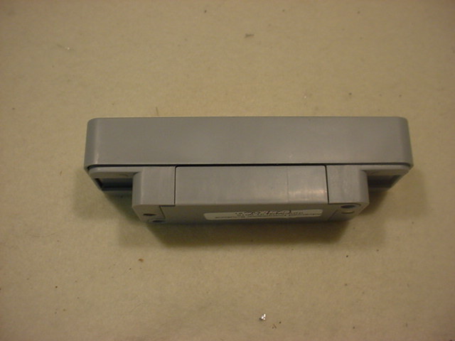
5015 B.U. Bowman Drive Buford, GA 30518 USA Voice: 770-831-8048 Fax: 770-831-8598 FCC Part 15.249 Certification Test Report FCC ID: U22GSESWW FCC Rule Part: 15.249 ACS Report Number: 07-0016-15C Manufacturer: Convia β A Herman Miller Company Model: Wireless Switch External Photos 5015 B.U. Bowman Drive Buford, GA 30518 USA Voice: 770-831-8048 Fax: 770-831-8598 Figure 1: Front View 5015 B.U. Bowman Drive Buford, GA 30518 USA Voice: 770-831-8048 Fax: 770-831-8598 Figure 2: Back View 5015 B.U. Bowman Drive Buford, GA 30518 USA Voice: 770-831-8048 Fax: 770-831-8598 Figure 3: Top View 5015 B.U. Bowman Drive Buford, GA 30518 USA Voice: 770-831-8048 Fax: 770-831-8598 Figure 4: Side View 5015 B.U. Bowman Drive Buford, GA 30518 USA Voice: 770-831-8048 Fax: 770-831-8598 Figure 5: Back View with Battery Dorr Open.
5015 B.U. Bowman Drive Buford, GA 30518 USA Voice: 770-831-8048 Fax: 770-831-8598 FCC Part 15.24 Certification Test Report FCC ID: U22GSESWW FCC Rule Part: 15.249 ACS Report Number: 07-0016-15C Manufacturer: Convia β A Herman Miller Company Model: Wireless Switch Label Information 5015 B.U. Bowman Drive Buford, GA 30518 USA Voice: 770-831-8048 Fax: 770-831-8598 Figure 1: Label Sample - Compliance Information Figure 2: Label Sample β Product Information Figure 3: Label Location Compliance Label Product Label
5015 B.U. Bowman Drive Buford, GA 30518 USA Voice: 770-831-8048 Fax: 770-831-8598 FCC Part 15.249 Certification Test Report FCC ID: U22GSESWW FCC Rule Part: 15.249 ACS Report Number: 07-0016-15C Manufacturer: Convia β A Herman Miller Company Model: Wireless Switch Internal Photos 5015 B.U. Bowman Drive Buford, GA 30518 USA Voice: 770-831-8048 Fax: 770-831-8598 Figure 1: RF PCB Front View 5015 B.U. Bowman Drive Buford, GA 30518 USA Voice: 770-831-8048 Fax: 770-831-8598 Figure 2: RF PCB Back View
5015 B.U. Bowman Drive Buford, GA 30518 USA Voice: 770-831-8048 Fax: 770-831-8598 FCC Part 15.249 Transmitter Certification Test Report FCC ID: U22GSESWW FCC Rule Part: 15.249 ACS Report Number: 07-0016-15C Manufacturer: Convia β A Herman Miller Company Model: Wireless Switch Test Begin Date: January 26, 2007 Test End Date: February 9, 2007 Report Issue Date: March 28, 2007 FOR THE SCOPE OF ACCREDITATION UNDER LAB Code 200612-0 This report is not be used to claim certification, approval, or endorsement by NVLAP, NIST or any government agency. Prepared by: Reviewed by: Jeff Woods Wireless Certifications Engineer ACS, Inc. J. Kirby Munroe Manager Wireless Certifications ACS, Inc. This test report shall not be reproduced except in full. This report may be reproduced in part with prior written consent of ACS, Inc. The results contained in this report are representative of the sample(s) submitted for evaluation. This report contains 15 pages 5015 B.U. Bowman Drive Buford, GA 30518 USA Voice: 770-831-8048 Fax: 770-831-8598 Table of Contents 1.0 General 3 1.1 Purpose 3 1.2 Product Description 3 1.2.1 General 3 1.2.2 Intended Use 3 1.3 Test Methodology and Considerations 3 2.0 Test Facilities 4 2.1 Location 4 2.2 Laboratory Accreditations/Recognitions/Certifications 4 2.3 Radiated Emissions Test Site Description 5 2.3.1 Semi-Anechoic Chamber Test Site 5 2.3.2 Open Area Tests Site (OATS) 6 2.4 Conducted Emissions Test Site Description 7 3.0 Applicable Standards and References 7 4.0 List of Test Equipment 8 5.0 Support Equipment 9 6.0 EUT Setup Block Diagram 9 7.0 Summary of Tests 10 7.1 Section 15.203 - Antenna Requirement 10 7.2 Section 15.207 β Power Line Conducted Emissions 10 7.3 Section 15.109 - Radiated Emissions (Unintentional Radiation) 10 7.3.1 Test Methodology 10 7.3.2 Test Results 10 7.4 Section 15.249(a) Fundamental Field Strength 11 7.4.1 Test Methodology 11 7.4.2 Test Results 11 7.5 Section 15.249(a) Radiated Spurious Emissions 11 7.5.1 Test Methodology 11 7.5.2 Test Results 12 7.5.3 Sample Calculations 12 7.6 Section 15.215 - 20dB Bandwidth 13 7.6.1 Test Methodology 13 7.6.2 Test Results 13 7.7 Section 15.249(d) β Band-edge Compliance and Spurious Emissions 14 7.7.1 Test Methodology 14 7.7.2 Test Results 14 8.0 CONCLUSION 15 Additional Exhibits Included In Filing Internal Photographs External Photographs Test Setup Photographs Product Labeling Schematics Installation/Users Guide Theory of Operation BOM (Parts List) System Block Diagram Model: Wireless Switch FCC ID: U22GSESWW ACS Report: 07-0016-15C Advanced Compliance Solutions Page 3 1.0 GENERAL 1.1 Purpose The purpose of this report is to demonstrate compliance with Part 15, Subpart C of the FCCβs Code of Federal Regulations. 1.2 Product Description 1.2.1 General The Wireless Switch can be used to control lights and other devices that are connected to Convia Smart Connectors. The user manually presses the up or down switch to turn selected light fixtures on and off. Detailed photographs of the EUT are filed separately with this filing. 1.2.2 Intended Use The Wireless Switch can be programmed to operate a wide configuration of light fixtures and also used to control dimming levels. The Wireless Switch will operate at a minimum of 75 feet from a Convia RF Wireless Coordinator. 1.3 Test Methodology and Considerations The model being used for compliance testing contains special test firmware that allows the unit to transmit continuously. All other transmit parameters, such as the RF power setting, are identical to the final product. When operating in the special test mode, the duty cycle is continuous (100%). The transmitter operates at its full data rate of 250 kbps and sends random data. Model: Wireless Switch FCC ID: U22GSESWW ACS Report: 07-0016-15C Advanced Compliance Solutions Page 4 2.0 TEST FACILITIES 2.1 Location The radiated and conducted emissions test sites are located at the following address: Advanced Compliance Solutions 5015 B.U. Bowman Drive Buford, GA 30518 Phone: (770) 831-8048 Fax: (770) 831-8598 2.2 Laboratory Accreditations/Recognitions/Certifications The Semi-Anechoic Chamber Test Site, Open Area Test Site (OATS) and Conducted Emissions Site have been fully described, submitted to, and accepted by the FCC, Industry Canada and the Japanese Voluntary Control Council for Interference by information technology equipment. In addition, ACS is compliant to ISO 17025 as certified by the National Institute of Standards and Technology under their National Voluntary Laboratory Accreditation Program. The following certification numbers have been issued in recognition of these accreditations and certifications: FCC Registration Number: 89450 Industry Canada Lab Code: IC 4175 VCCI Member Number: 1831 Β VCCI OATS Registration Number R-1526 Β VCCI Conducted Emissions Site Registration Number: C-1608 NVLAP Lab Code: 200612-0 Model: Wireless Switch FCC ID: U22GSESWW ACS Report: 07-0016-15C Advanced Compliance Solutions Page 5 2.3 Radiated Emissions Test Site Description 2.3.1 Semi-Anechoic Chamber Test Site The Semi-Anechoic Chamber Test Site consists of a 20β x 30β x 18β shielded enclosure. The chamber is lined with Toyo Ferrite Grid Absorber, model number FFG-1000. The ferrite tile grid is 101 x 101 x 19mm thick and weighs approximately 550 grams. These tiles are mounted on steel panels and installed directly on the inner walls of the chamber. The turntable is 150cm in diameter and is located 160cm from the back wall of the chamber. The chamber is grounded via 1 - 8β copper ground rod, installed at the center of the back wall, it is bound to the ground plane using 3/4" stainless steel braided cable. The turntable is all steel, flush mounted table installed in an all steel frame. The table is remotely operated from inside the control room located 25β from the range. The turntable is electrically bonded to the surrounding ground plane via steel fingers installed on the edge of the turn table. The steel fingers make constant conβ¦
Text truncated - open the document above for the full version.
5015 B.U. Bowman Drive Buford, GA 30518 USA Voice: 770-831-8048 Fax: 770-831-8598 FCC Part 15.249 Certification Test Report FCC ID: U22GSESWW FCC Rule Part: 15.249 ACS Report Number: 07-0016-15C Manufacturer: Convia β A Herman Miller Company Model: Wireless Switch Test Set Up Photos 5015 B.U. Bowman Drive Buford, GA 30518 USA Voice: 770-831-8048 Fax: 770-831-8598 Figure 1: Radiated Emissions 5015 B.U. Bowman Drive Buford, GA 30518 USA Voice: 770-831-8048 Fax: 770-831-8598 Figure 2: Radiated Emissions.
| # | Rule Parts | Frequency Range | Power Output |
|---|---|---|---|
| 1 | 15C | 2.41 GHz - 2.47 GHz | - |

WIRELESS SWITCH COORDINATOR
Equipment Class
DXX - Part 15 Low Power Communication Device Transmitter