U25PAH-1000WIRELESS MICROPHONE
Enping Pasgao Audio Epuipment Factory
Click to zoom
Application Details
- Equipment Class
- TBF - Licensed Broadcast Transmitter Held to Face
- Date of Grant
- Dec 08, 2010
- Application Purpose
- Original Equipment
- Date of Application
- Dec 08, 2010
- Equipment Note
- WIRELESS MICROPHONE
- Frequency Range
- 655.00000000 - 679.00000000
- Country
- China
Documents & Files
Document Text
Text extracted from the exhibit documents filed with the FCC. Open a document above to read the original.
Users Manual
UHF PLL Diversity Wireless Receiver Wireless Microphone Systems User Guide 12 PAW-1000 System Frequency Band Selection Congratulations! Welcome to the PAW-1000 wireless system. To users who need to build an advanced UHF radio system, PAW-1000 provides an excellent solution. With 160 frequency bands, PAW-1000 is applicable for various occasions of radio-cast such as live shows, broadcast, meetings, instrument pickups etc. Touch buttons and liquid crystal displays are equipped within all the components for fast and simple system setup. Most countries closely regulate the radio frequencies used in the transmission of wireless information. These regulations state which devises can use which frequencies, and help to limit the amount of RF (radio frequency) interference in all wireless communications. To be flexible enough to operate worldwide, PAW-1000 system offers a number of frequency ranges. You can choose an appreciate one according to the wireless regulation in your area.Available bands are: UA: 518-548MHz UB: 630-660z UC: 740-770z UD: 800-822z UE: 838-865 MH MH MH MHz To facilitate system setup and protect against RF interference, each system comes with multiple predefined frequency groups and channels. When using a single PAW-1000 system, the operating frequency will generally not have to be changed. In an installation with multiple receiver/transmitter systems, each system must operate on a separate channel. The group and channel system provides an optimum frequency spread when using multiple receiver/transmitter systems. Within a single frequency band, up to 16 individual receiver/transmitter systems may be used in a single installation. System Components PAW-1000 Receiver Features PAH-720 Handheld Transmitter PAH-813 Handheld Transmitter PBT-900 Body Pack Transmitter PBT-1000 Body Pack Transmitter System Setup Rack-Mounting the Receivers Tips for Improving System Performance Troubleshooting Specifications PAH-1000 Handheld Transmitter CATALOGUE 3 4 5 6 7 8 9 10 11 12 12 13 3 4 - + - + PL-10 PL-20PH-20 PH-10 Wireless Microphone Systems User Guide TMglobal sound 1 2 10 3 4 5 6 7 8 9 123456 PBT-1000 UHF PLL BodyPack Transmitter 11 12 On/Off switch Infrared (IR) window Channel 1 LCD panel Please see System Setup on Page 10“” System menu upward button Please see System Setup on Page 10“” System menu downward button Please see System Setup on Page 10“” Sync Button Press to initiate IR connection between receiver and transmitter. System setup button Please see System Setup on Page 10“” Antenna A receiver indicator light Light glows when Antenna A is on . Antenna B RF indicator light Antenna B receiver indicator light Light glows when Antenna B is on . Channel 1 audio indicator light Antenna A RF indicator light 1 2 3 4 5 6 DC power adapter socket Fine adjustment of mute threshold level It is the mute enabling threshold value, which is factory setting and usually does not need to be adjusted. If there are any interference signals, this threshold value can be increased by turning the knob clockwise until RF signal lamp goes out. 1/4in output socket XLR output socket Antenna Jack A 50 ohm. Antenna Jack B 50 ohm PAW-1000 Receiver Features Front Panel Rear Panel PAW-1000 receiver 2 AA batteries“” A 1/4 RF connector” Power supply Two antennas PA-D40 User guide PAH-1000 / PAH-720 / PAH-813 handheld transmitter PBT-1000/PBT-900 bodypack transmitter Microphone (choice of PL-10or PL-20 lavalier, PH-10 or PH-20 headworn) System Components All systems include: Vocalist system includes: Lavalier/ Headworn system includes: bodypack transmitter 1/4 to mini 3-pin guitar cable ” Guitar system includes 11 2345678 9 1 10 12 LAMP POWER ASC BATT PBT-1000 PBT-900 PAH-1000 PAH-813 PAH-720 PBT-1000 UHF PLL BodyPack Transmitter LAMP POWER ASC BATT PBT-1000 PBT-900 6 BATT 1 INFRARED INFRAREDBATT 6 Condensor mic Dynamic mic LCD screen Power source controlling switch Microphone input sensitivity adjustment. Left turn for output level decrease, right turn for output level increase. 10hours PAH-720 Handheld Transmitter Functions: 1 2 3 4 5 1 2 3 4 5 6 The handheld transmitter had five levels as shown on the left. After the finishing the connection of the receiver and the transmitter, the transmitters receiver keeps displaying the numbers of the group and channel for 5 seconds, as shown on the left, then back to the normal status display. The transmitters shows battery power and working frequency, as shown on the left. Battery Status: Group and Channel Display: Normal Display: Transmitter Status Display 1 2 3 5 Functions: 1 2 3 4 Interchangeable microphone head. LCD screen Power/Mute Control switch Middle position is Mute. IR Window This window receives infrared signal so as to keep frequency synchronization. Select button Battery Replacement The life expectancy of two alkaline batteries is about 10 hours. When the power indication symbol on the display screen keeps flashing as shown in the left diagram, the batteries should be re placed immediately, as shown in the above. CLOSEOPEN Push the button 2 second, the display will skip to the group MUTE/ and channel selection. Continuously push two times on the MUTE/ button to turn on function, to turn off the functionMUTE/ MUTE/ with the same operation. Manually selecting the group and channel: Pushing on the select button until the group and channel display alternately, push the button while the group on the display to change on the group, push the button while the channel on display to change the channel. Transmitter data lock and unlock: Push the mute and select bottom at the same time can lock and unlock the transmitter data. On the lock working condition, you can not change the setting on the transmitter, but it will not lock the infrared synchronizer. Battery displayer: Display the transmitter battery level. select select select select + Transmitter Status Display Handheld Transmitter 1 2 4 3 PAH-1000 Handheld Transmitter INFRARED BATT INFRARED BATT INFRAREDBATT 1 2 3…
Text truncated - open the document above for the full version.
Cover Letter(s)
Enping Pasgao Audio Equipment Factory Add: 5th,Dianli Industry Building, XinPing BeiLu, EnPing City, Guangdong Province, China. Tel: +86-574-87576644 Fax: +86-574-87576884 FCC ID: U25PAH-1000 Power of Attorney To Whom It May Concern: We, the undersigned, hereby authorize Guangzhou Huesent Testing Service Co., Ltd. ( Jerry Chen ) on our behalf, to apply to the Federal Communications Commission on our equipment. Any and all acts carried out by Guangzhou Huesent Testing Service Co., Ltd. on our behalf shall have the same effect as acts of our own. This authorization expires on 2011-2-3 Sincerely, Signature of Authorized Applicant: 2010-12-5
External Photos
PAH-1000
ID Label/Location Info
FCC ID Label Sample FCC ID: U25PAH-1000 This device complies with Part 74 of the FCC Rules.
ID Label/Location Info
FCCID Label Location
Internal Photos
Internal Photographs of PAH-1000 FCCID: U25PAH-1000
Operational Description
Wireless microphone circuit description of U25PAH-1000 AUDIO CIRCUIT The audio signal is injected via the microphone sensor into the audio circuit composed of the op. amp IC4 (MC4558), & compandor IC3 (SA571). The signal is compressed via the compandor circuit at a 2:1 ratio and is pre-emphasized by U2. The level of the output signal is controlled by the resistors R45 (10K VR) and R37, R47 to VCO. MODULATOR CIRCUIT The modulator circuit is a direct FM type built around the local oscillator controlled by Crystal X301(10MHz), VCO(IC302 MCD8825B), PLL(IC301 MB15E03). The modulated output from the oscillator is sent to the RF pre-amp. Frequency Set: The frequency can be chosen by setting switch (AN1) or by an IR sensor and the CPU(IC1 16F73 clock 4MHz). And the signal from CPU to PLL can control the carrier frequency. RF PRE-AMPLIFIER & FINAL AMPLIFIER The 2-stage amplifier, using two transistors Q303(Y7) and Q304(R37), culminating with a normal transmitter output of <1mW. The precious LC output filter (L310-314, C333-342) suppress the output harmonics and matches the output to the integrate antenna. LCD DISPLAY CIRCUIT The LCD display (LCD T4036) is driven by IC5(HT1621) and showing the frequency etc. signals output by CPU. POWER STEADY CIRCUIT Use 2xAA batteries as power supply, Q4 (2SC4081) and Q3 (2SD2098) rise the voltage to 7.5V for audio part, and to U1(7805 5V) for CPU also the LCD, PLL and RF AMP. ANT TYPE: Whip ant Modulation Type: 100KF3E Operational frequency range: 655M—679M Hz
Parts List/Tune Up Info
12345678 A B C D 87654321 D C B A Title NumberRevisionSize A3 Date:11-Nov-2008Sheet of File:E:\pcb\PLL.DDBDrawn By: SEG7 1 SEG6 2 SEG5 3 SEG4 4 SEG3 5 SEG2 6 SEG1 7 SEG0 8 CS 9 RD 10 WR 11 DATA 12 VSS 13 OSCO 14 NC 15 OSCI 16 VDD/VLCD 17 IRQ 18 BZ 19 BZ 20 COM1 21 COM2 22 COM3 23 COM4 24 SEG31 25 SGE30 26 SEG29 27 SEG28 28 SEG27 29 SEG26 30 SEG25 31 SEG24 32 SEG23 33 SEG22 34 SEG21 35 SEG20 36 SEG19 37 SEG18 38 SEG17 39 SEG16 40 SEG15 41 SEG14 42 SEG13 43 SEG12 44 SEG11 45 SEG10 46 SEG9 47 SEG8 48 IC5 HT1621 5V R15 15K COM1 1 COM2 2 COM3 3 COM4 4 4F/4G/4E/4D 5 4A/4B/4C 6 5F/5G/5E/5D 7 5A/5B/5C 8 6F/6G/6E/6D 9 6A/6B/6C/MHZ 10 S2/S3/S4/S5 11 */*/S1/BATT 12 3A/3B/3C/DP 13 3F/3G/3E/3D 14 2A/2B/2C 15 2F/2G/2E/2D 16 1A/1B/1C 17 1F/1G/1E/1D 18 LCD1 LCD_T4036 R5 100k 1 2 3 R14 红外线接收头 V C C 8 W P 7 S C L 6 S D A 5 A 0 1 A 1 2 A 2 3 V s s 4 IC2 24CXX X1 C2 4M C3 30P R2 50K C1 1u 5V MLCR 1 RA0 2 RA1 3 RA2 4 RA3 5 RA4 6 RA5 7 VSS 8 OSC1 9 OSC2 10 RC0 11 RC1 12 RC2 13 RC3 14 RC4 15 RC5 16 RC6 17 RC7 18 VSS 19 VDD 20 RB0 21 RB1 22 RB2 23 RB3 24 RB4 25 RB5 26 RB6 27 RB7 28 IC1 16F73 PE1 DATA1 CLOCK1 VCC GND VPP DATA I/O CLK R7 100K R8 100K R9 100K R13 100K 5V R3 1k AN1 POWER 5v Batty R1 5K BT1 电池 2 1 D1 DIODE Q1 NPN_2 Q2 PNP_2 R6 1k V i n 3 GND 2 V o u t 1 U1 78L05 R4 1k 其他电路 - C14 100u 2 1 D2 DIODE 其他5V电路 R11 100K R10 100K 背光控制 TO PLL A D J 8 O U T 1 7 R F 1 6 - I N 5 G N D 4 G I N 3 R I N 2 C F 1 C F 2 1 6 R I N 2 1 5 G I N 2 1 4 V C C 1 3 - I N 2 1 2 R F 2 1 1 O U T 2 1 0 A D J 9 IC3 SA571 R5 4.7K R34 47K R16 1K R38 2.2K - C9 4.7u - C10 4.7u - C4 4.7u - C7 4.7u - C8 4.7u 5 6 7 IC4B MC4558 VCC+ 8 VCC- 4 IC4C MC4558 3 2 1 IC4A MC4558 C78 220P C20 103 Q99014 R36 10K D5 4148 D6 4148 C79 102 C 2 1 103 R12 10K R26 33K R39 2K2 C67 100P C81 10P C26 1 0 4 R41 22K R42 22K R43 3K3 - C11 4.7u - C5 4 . 7 u - C12 4.7u R25 33K - C13 0.1U - C74 1u C22103 - C73 1u R45 10K AF R37 47K R402K2 R44 3K3 C80 102 - C75 1u 7.5V 7.5V AF R16 1K - C4 4.7u C20 103 MK1 MICROPHONE2 7V5 R18 10K R17 820 R19 4K7 Q4 2SC4081 Q3 2SD2098 D4 7.5V - C5 100u - C4 100u C9 104 C10 104 C7 22P C8 104 L1 100uH L2 100uH 21 D3 SS14 - C6 100u POWER R310 3.3K X301 10M C308 30P C311 103 C312 103 - C313 1U - C314 47U R304 4.7K R306 10K C310 22P OSC_IN 1 OSC_OUT 2 VP 3 VCC 4 DO 5 GND 6 Xfin 7 fin 8 R 16 P 15 LD/fout 14 ZC 13 PS 12 LE 11 Data 10 Clock 9 IC301 MB15E03 5V 3V R305 330 R311 680 R312 47 L 3 0 6 1 R 0 C322 3P L 3 0 7 1 0 N C325 104 C324 47P C327 3P Q303 7Y 5V L 3 0 9 6 8 N C331 102 C 3 3 2 4 7 P C330 104 C326 102 L 3 0 8 1 R 0 R313 3.3K C336 101 C337 104 C335 103 L310 15N C334 47P C338 3P L312 15N C333 2P TX1 ANTENNA L302 1R0 L301 1R0 R301 100 C305 100P C304 100P C306 100P C301 100P C302 100P C303 100P A F C309 103 3V AMP PLL PE1 DATA1 CLOCK1 R303 47 Q304 R37 R315 47 R314 1K L313 15N L314 15N C339 0P C341 3P C342 3P C340 3P C323 103 - C319 4.7U - C328 4.7U - C329 4.7U 654 321 IC302 VCO L 3 0 3 6 8 N C316 103 L304 1R0 C320 3P L 3 0 5 1 5 N L311 15N R302 22 5V C321 103 C318 103 - C317 4.7U C307 47P C315 103 L315 1R0 C343 103 - C344 4.7U C345 103 C346 103 - C347 4.7U
Schematics
12345678 A B C D 87654321 D C B A Title NumberRevisionSize A3 Date:11-Nov-2008Sheet of File:E:\pcb\PLL.DDBDrawn By: SEG7 1 SEG6 2 SEG5 3 SEG4 4 SEG3 5 SEG2 6 SEG1 7 SEG0 8 CS 9 RD 10 WR 11 DATA 12 VSS 13 OSCO 14 NC 15 OSCI 16 VDD/VLCD 17 IRQ 18 BZ 19 BZ 20 COM1 21 COM2 22 COM3 23 COM4 24 SEG31 25 SGE30 26 SEG29 27 SEG28 28 SEG27 29 SEG26 30 SEG25 31 SEG24 32 SEG23 33 SEG22 34 SEG21 35 SEG20 36 SEG19 37 SEG18 38 SEG17 39 SEG16 40 SEG15 41 SEG14 42 SEG13 43 SEG12 44 SEG11 45 SEG10 46 SEG9 47 SEG8 48 IC5 HT1621 5V R15 15K COM1 1 COM2 2 COM3 3 COM4 4 4F/4G/4E/4D 5 4A/4B/4C 6 5F/5G/5E/5D 7 5A/5B/5C 8 6F/6G/6E/6D 9 6A/6B/6C/MHZ 10 S2/S3/S4/S5 11 */*/S1/BATT 12 3A/3B/3C/DP 13 3F/3G/3E/3D 14 2A/2B/2C 15 2F/2G/2E/2D 16 1A/1B/1C 17 1F/1G/1E/1D 18 LCD1 LCD_T4036 R5 100k 1 2 3 R14 红外线接收头 V C C 8 W P 7 S C L 6 S D A 5 A 0 1 A 1 2 A 2 3 V s s 4 IC2 24CXX X1 C2 4M C3 30P R2 50K C1 1u 5V MLCR 1 RA0 2 RA1 3 RA2 4 RA3 5 RA4 6 RA5 7 VSS 8 OSC1 9 OSC2 10 RC0 11 RC1 12 RC2 13 RC3 14 RC4 15 RC5 16 RC6 17 RC7 18 VSS 19 VDD 20 RB0 21 RB1 22 RB2 23 RB3 24 RB4 25 RB5 26 RB6 27 RB7 28 IC1 16F73 PE1 DATA1 CLOCK1 VCC GND VPP DATA I/O CLK R7 100K R8 100K R9 100K R13 100K 5V R3 1k AN1 POWER 5v Batty R1 5K BT1 电池 2 1 D1 DIODE Q1 NPN_2 Q2 PNP_2 R6 1k V i n 3 GND 2 V o u t 1 U1 78L05 R4 1k 其他电路 - C14 100u 2 1 D2 DIODE 其他5V电路 R11 100K R10 100K 背光控制 TO PLL A D J 8 O U T 1 7 R F 1 6 - I N 5 G N D 4 G I N 3 R I N 2 C F 1 C F 2 1 6 R I N 2 1 5 G I N 2 1 4 V C C 1 3 - I N 2 1 2 R F 2 1 1 O U T 2 1 0 A D J 9 IC3 SA571 R5 4.7K R34 47K R16 1K R38 2.2K - C9 4.7u - C10 4.7u - C4 4.7u - C7 4.7u - C8 4.7u 5 6 7 IC4B MC4558 VCC+ 8 VCC- 4 IC4C MC4558 3 2 1 IC4A MC4558 C78 220P C20 103 Q99014 R36 10K D5 4148 D6 4148 C79 102 C 2 1 103 R12 10K R26 33K R39 2K2 C67 100P C81 10P C26 1 0 4 R41 22K R42 22K R43 3K3 - C11 4.7u - C5 4 . 7 u - C12 4.7u R25 33K - C13 0.1U - C74 1u C22103 - C73 1u R45 10K AF R37 47K R402K2 R44 3K3 C80 102 - C75 1u 7.5V 7.5V AF R16 1K - C4 4.7u C20 103 MK1 MICROPHONE2 7V5 R18 10K R17 820 R19 4K7 Q4 2SC4081 Q3 2SD2098 D4 7.5V - C5 100u - C4 100u C9 104 C10 104 C7 22P C8 104 L1 100uH L2 100uH 21 D3 SS14 - C6 100u POWER R310 3.3K X301 10M C308 30P C311 103 C312 103 - C313 1U - C314 47U R304 4.7K R306 10K C310 22P OSC_IN 1 OSC_OUT 2 VP 3 VCC 4 DO 5 GND 6 Xfin 7 fin 8 R 16 P 15 LD/fout 14 ZC 13 PS 12 LE 11 Data 10 Clock 9 IC301 MB15E03 5V 3V R305 330 R311 680 R312 47 L 3 0 6 1 R 0 C322 3P L 3 0 7 1 0 N C325 104 C324 47P C327 3P Q303 7Y 5V L 3 0 9 6 8 N C331 102 C 3 3 2 4 7 P C330 104 C326 102 L 3 0 8 1 R 0 R313 3.3K C336 101 C337 104 C335 103 L310 15N C334 47P C338 3P L312 15N C333 2P TX1 ANTENNA L302 1R0 L301 1R0 R301 100 C305 100P C304 100P C306 100P C301 100P C302 100P C303 100P A F C309 103 3V AMP PLL PE1 DATA1 CLOCK1 R303 47 Q304 R37 R315 47 R314 1K L313 15N L314 15N C339 0P C341 3P C342 3P C340 3P C323 103 - C319 4.7U - C328 4.7U - C329 4.7U 654 321 IC302 VCO L 3 0 3 6 8 N C316 103 L304 1R0 C320 3P L 3 0 5 1 5 N L311 15N R302 22 5V C321 103 C318 103 - C317 4.7U C307 47P C315 103 L315 1R0 C343 103 - C344 4.7U C345 103 C346 103 - C347 4.7U
Test Report
FCCID: U25PAH-1000 Report Number: HST201011-4362-FCC Page 1 of 22 Test Report Applicant: Enping Pasgao Audio Equipment Factory Address of Applicant: 5th, DianLi Industry Building, Xinping Beilu, Enping City, Guangdong, CHINA Equipment Under Test (EUT): EUT Name: UHF Wireless Microphone Model No.: PAH-1000, PBT-1000, PAH-315, PBT-305 Trade Mark: NA Serial No.: Not supplied by client Standards: FCC PART 74H:2010 Date of Receipt: Nov. 25, 2010 Date of Test: Nov. 30 to Dec. 2, 2010 Date of Issue: Dec 3, 2010 Test Result : PASS* z In the configuration tested, the EUT complied with the standards specified above. Authorized Signature: Henly Xie / Manager This report refers to the General Conditions for Inspection and Testing Services, printed overleaf This report details the results of the testing carried out on one sample. The results contained in this test report do not relate to other samples of the same product. The manufacturer should ensure that all products in series production are in conformity with the product sample detailed in this report. This report may only be reproduced and distributed in full. If the product in this report is used in any configuration other than that detailed in the report, the manufacturer must ensure the new system complies with all relevant standards. The report must not be used by the client to claim product certification, approval, or endorsement by NVLAP, NIST, or any agency of the federal government. All test results in this report can be traceable to National or International Standards. The test report prepare by: Guangzhou Huesent Testing Service Co., Ltd. No.91, Dongguanzhuang Road, Tianhe District, Guangzhou, China. Tel: 86-20-28263298 Fax: 86-20-28263237 http://www.hst.org.cn E-mail: [email protected] REPORT No: HST201011-4362-FCC Page 2 of 22 Contents 1 TEST SUMMARY .................................................................................................................3 2 GENERAL INFORMATION .................................................................................................. 4 2.1 Client Information ..........................................................................................................4 2.2 General Description of E.U.T......................................................................................... 4 2.3 Details of E.U.T. ............................................................................................................ 4 2.4 Description of Support Units.......................................................................................... 4 2.5 Standards Applicable for Testing ................................................................................... 4 2.6 Test Location ................................................................................................................. 5 2.7 Deviation from Standards .............................................................................................. 5 2.8 Abnormalities from Standard Conditions ....................................................................... 5 3 EQUIPMENTS USED DURING TEST ................................................................................. 6 4 TEST RESULTS ................................................................................................................... 7 4.1 E.U.T. Operation Condition ........................................................................................... 7 4.2 Test Procedure & Measurement Data ........................................................................... 8 4.2.1 Carrier Radiated Power & Radiated Spurious Emissions ............................... 8 4.2.2 Occupied Bandwidth ..................................................................................... 11 4.2.3 Frequency Stability ....................................................................................... 14 4.2.4 Modulation Characteristics............................................................................ 16 4.3 EUT Constructional Details ......................................................................................... 19 REPORT No: HST201011-4362-FCC Page 3 of 22 1 Test Summary Test Test Requirement Standard Paragraph Result Carrier Radiated Power FCC Part 2.1046 74.861 e) 1) 54–72, 76–88 & 174–216 MHz bands, 50 mW 470–608 and 614–806 MHz bands, 250 mW PASS Modulation Deviation FCC Part 2.1047 74.861 e) 3) Within 75kHz PASS Frequency Stability FCC Part 2.1055 74.861 e) 4) <0.005% 50 ppm PASS Operating Bandwidth FCC Part 2.1049 c) 74.861 e) 5) Within 200kHz PASS Unwanted Radiation FCC Part 2.1049 c) 74.861 e) 6) within the mask PASS Radiated Spurious Emission FCC Part 2.1053 74.861 d) 3) < 43+10lgP(W) dB PASS Remark: ♣The EUT has one channel, which is located in the range 655.000 MHz to 679.000MHz . Only test result of a sample in channels 655.2 MHz, 667.1 MHz and 678.8 MHz were recorded in this report. REPORT No: HST201011-4362-FCC Page 4 of 22 2 General Information 2.1 Client Information Applicant: Enping Pasgao Audio Equipment Factory Address of Applicant: 5th, DianLi Industry Building, Xinping Beilu, Enping City, Guangdong, CHINA 2.2 General Description of E.U.T. EUT Name: UHF Wireless Microphone Item No.: PAH-1000, PBT-1000, PAH-315, PBT-305 Tested PAH-1000 only, since the other models are electrical identical to PAH-1000 except the model No. and the color of outlook . Serial No.: Not supplied by client 2.3 Details of E.U.T. Power Supply: 3Vdc, 2 x AA size Battery Main Function: Wireless microphone system with an associated receiver for transmitting voice. The final amplifier Collector Voltage and Collector Current are 0.3V & 3.5mA respectively. Necessary Bandwidth: 2M+2DK= 2 x 30kHz + 2 x 20kHz x 1.0 = 100 kHz 2.4 Description of Support Units Connect the EUT to mains power, and then test the EUT with signal generator. 2.5 Standards Applicable for Testing The standard used was FCC PART 74H, 2008 The EUT belongs to licensed low power auxiliary device…
Text truncated - open the document above for the full version.
Test Setup Photos
FCC ID: U25PAH-1000 SETUP
Contact Information
Applicant
Yupeng Hu(General Manager)
Test Firm
China CEPREI LaboratoryLihui Chen
Technical Specifications
| # | Rule Parts | Frequency Range | Power Output | Emission | Tolerance |
|---|---|---|---|---|---|
| 1 | 74.861 | 655 MHz - 679 MHz | 1.00 mW | 100KF3E | 4.2000000000 ppm |
Other Applications from Enping Pasgao Audio Epuipment Factory
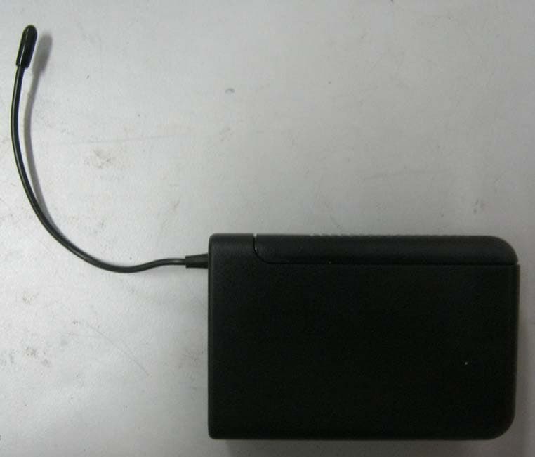
U25S1690T
Aug 08, 2012Transmitter
Equipment Class
TBT - Licensed Broadcast Transmitter Worn on Body
U25RW-100HT
May 31, 2012Transmitter
Equipment Class
TBF - Licensed Broadcast Transmitter Held to Face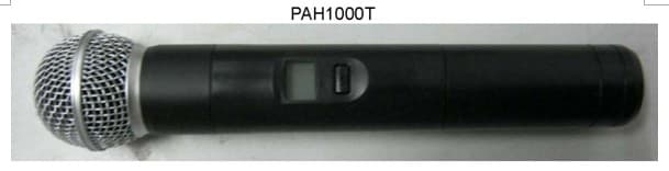
U25PAH1000T
May 29, 2012Transmitter
Equipment Class
TBF - Licensed Broadcast Transmitter Held to Face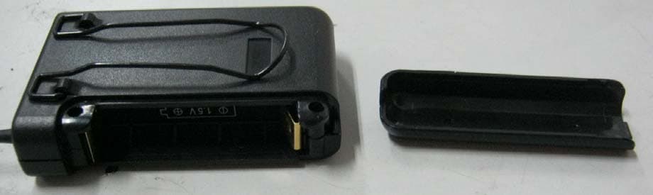
U25PV60T
May 29, 2012Transmitter
Equipment Class
TBT - Licensed Broadcast Transmitter Worn on Body
U25PAH-710
Feb 27, 2007Wireless Microphone Transmitter
Equipment Class
TBF - Licensed Broadcast Transmitter Held to Face