U2QTXRX10002000AMotion Detector Alarm
Rodann Electronics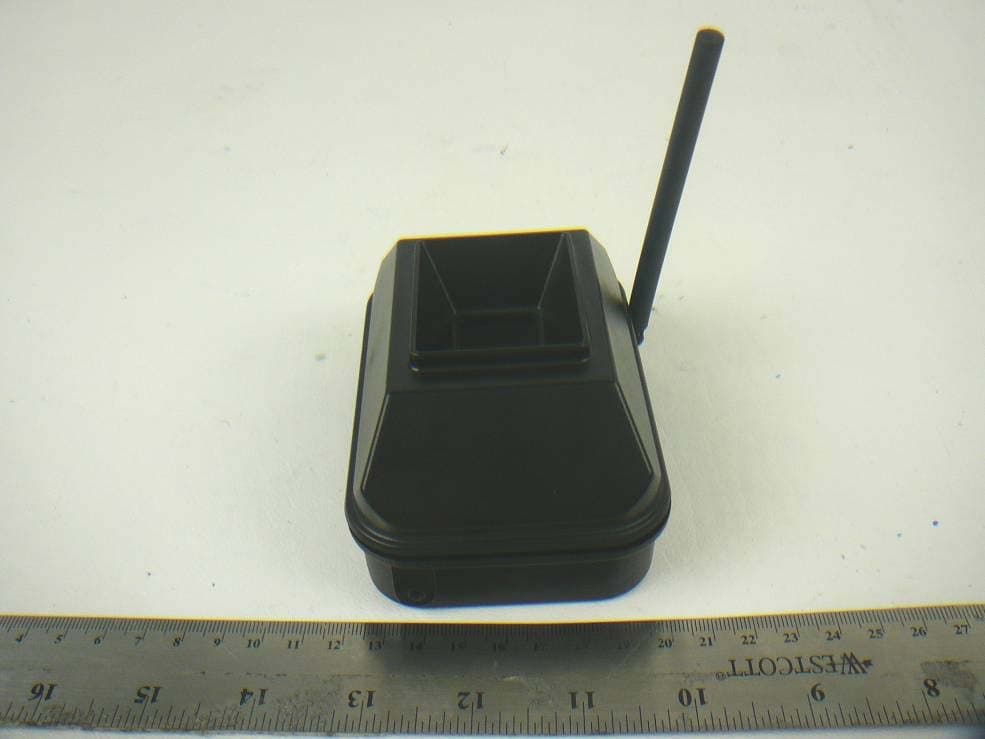
Click to zoom
Application Details
- Equipment Class
- DSC - Part 15 Security/Remote Control Transmitter
- Date of Grant
- Mar 26, 2012
- Application Purpose
- Original Equipment
- Date of Application
- Mar 26, 2012
- Equipment Note
- Motion Detector Alarm
- Frequency Range
- 418.00000000 - 418.00000000
- Company
- Rodann Electronics
- Country
- United States
Documents & Files
Document Text
Text extracted from the exhibit documents filed with the FCC. Open a document above to read the original.
External Photos
Rodann Electronics Mfg. Co. FCC ID: U2QTXRX10002000A Report Number: R1110113-231 Page 26 of 28 FCC Part 15C Report 10 EXHIBIT C - EUT PHOTOGRAPHS 10.1 EUT - Side View 10.2 EUT - Top View
Internal Photos
Rodann Electronics Mfg. Co. FCC ID: U2QTXRX10002000A Report Number: R1110113-231 Page 27 of 28 FCC Part 15C Report 10.3 EUT – Cover off View 10.4 EUT – PCB Top View Rodann Electronics Mfg. Co. FCC ID: U2QTXRX10002000A Report Number: R1110113-231 Page 28 of 28 FCC Part 15C Report 10.5 EUT – PCB Bottom View --- End of Report ---
Operational Description
CIRCUIT DESCRIPTION FOR RXTX10002000A The TX unit is a 9VDC battery powered motion detector wireless transmitter. The dual element pyro detector picks up a change in temperature in motion and activates the wireless transmission circuit as shown in the schematic. This RF circuit transmits at 418 Mhz to a waiting receiver (RX) This circuit through its 6 dipswitches allows for 16 different addresses that are available on the transmitter and 4 different tones available to on the RX (receiver unit). These devices, The RX and TX units are used to announce the entry of either a person or a vehicle when passing through the system. The RX (receiver) uses a 12VDC 500ma power supply that plugs into any 110 volt AC outlet. This unit waits for a signal from the TX (transmitter) unit and activates 4 different tones that the owner can choose from. This unit also allows you to add different devices to the back such as strobe, siren, buzzer, counter, or an additional speaker. This unit has a speaker built into the box. It also operates at 418 Mhz as shown in the schematic.
Test Report
Note: This test report is prepared for the customer shown above and for the device described herein. It may not be duplicated or used in part without prior written consent from Bay Area Compliance Laboratories Corp. This report must not be used by the customer to claim product certification, approval, or endorsement by NVLAP*, NIST, or any agency of the Federal Government. * This report may contain data that are not covered by the NVLAP accreditation and are marked with an asterisk “*” (Rev.2) FCC PART 15C MEASUREMENT AND TEST REPORT For Rodann Electronic Mfg. Co. 1819 S.W. Troon Avenue, Bend, OR 97702, USA FCC ID: U2QTXRX10002000A Report Type: Original Report Product Type: Motion Detector Alarm Test Engineer: Angel Escamilla Report Number: R1110113-231 Report Date: 2012-03-13 Reviewed By: Victor Zhang EMC/RF Lead Prepared By: (SP) Bay Area Compliance Laboratories Corp. 1274 Anvilwood Avenue, Sunnyvale, CA 94089, U.S.A. Tel: (408) 732-9162 Fax: (408) 732-9164 Rodann Electronics Mfg. Co. FCC ID: U2QTXRX10002000A Report Number: R1110113-231 Page 2 of 28 FCC Part 15C Report TABLE OF CONTENTS 1 GENERAL INFORMATION ..............................................................................................................................5 1.1 PRODUCT DESCRIPTION FOR EQUIPMENT UNDER TEST (EUT).........................................................................5 1.2 MECHANICAL DESCRIPTION............................................................................................................................5 1.3 OBJECTIVE.......................................................................................................................................................5 1.4 RELATED SUBMITTAL(S)/GRANT(S) ................................................................................................................5 1.5 TEST METHODOLOGY......................................................................................................................................5 1.6 MEASUREMENT UNCERTAINTY.......................................................................................................................5 1.7 TEST FACILITY.................................................................................................................................................6 2 SYSTEM TEST CONFIGURATION..................................................................................................................7 2.1 JUSTIFICATION.................................................................................................................................................7 2.2 EUT EXERCISE SOFTWARE..............................................................................................................................7 2.3 SPECIAL ACCESSORIES....................................................................................................................................7 2.4 EQUIPMENT MODIFICATIONS...........................................................................................................................7 2.5 POWER SUPPLY AND LINE FILTERS..................................................................................................................7 2.6 LOCAL SUPPORT EQUIPMENT..........................................................................................................................7 2.7 INTERFACE PORTS AND CABLING....................................................................................................................7 2.8 EUT INTERNAL CONFIGURATION DETAILS......................................................................................................7 2.9 TEST SETUP BLOCK DIAGRAM.........................................................................................................................8 3 SUMMARY OF TEST RESULTS.......................................................................................................................9 4 FCC §15.203 – ANTENNA REQUIREMENT..................................................................................................10 4.1 APPLICABLE STANDARD................................................................................................................................10 4.2 TEST RESULT.................................................................................................................................................10 5 FCC §15.231(A) – ECTECTIVE TESTING .....................................................................................................11 5.1 APPLICABLE STANDARD................................................................................................................................11 5.2 TEST EQUIPMENT LIST AND DETAILS............................................................................................................11 5.3 TEST ENVIRONMENTAL CONDITIONS.............................................................................................................11 5.4 TEST RESULT.................................................................................................................................................12 6 FCC §15.205, §15.209 & §15.231(B) – FIELD STRENGTH OF EMISSIONS..............................................13 6.1 APPLICABLE STANDARD................................................................................................................................13 6.2 TEST EQUIPMENT LIST AND DETAILS............................................................................................................15 6.3 RADIATED EMISSIONS EUT SETUP................................................................................................................15 6.4 TEST PROCEDURE..........................................................................................................................................16 6.5 CORRECTED AMPLITUDE & MARGIN CALCULATION..........................................................…
Text truncated - open the document above for the full version.
Test Setup Photos
Rodann Electronics Mfg. Co. FCC ID: U2QTXRX10002000A Report Number: R1110113-231 Page 24 of 28 FCC Part 15C Report 9 EXHIBIT B - TEST SETUP PHOTOGRAPHS 9.1 Radiated Emissions below 1 GHz - Front View 9.2 Radiated Emissions below 1 GHz – Rear View Rodann Electronics Mfg. Co. FCC ID: U2QTXRX10002000A Report Number: R1110113-231 Page 25 of 28 FCC Part 15C Report 9.3 Radiated Emissions above 1 GHz - Front View 9.4 Radiated Emissions above 1 GHz – Rear View
Contact Information
Applicant
Alex V Skarbek(President)
Test Firm
Bay Area Compliance LaboratoryJohn Chan
Technical Specifications
| # | Rule Parts | Frequency Range | Power Output |
|---|---|---|---|
| 1 | 15.231 | 418 MHz - 418 MHz | - |