U3FHOMECELL20Celluar Amplifier
HomeCell, LLC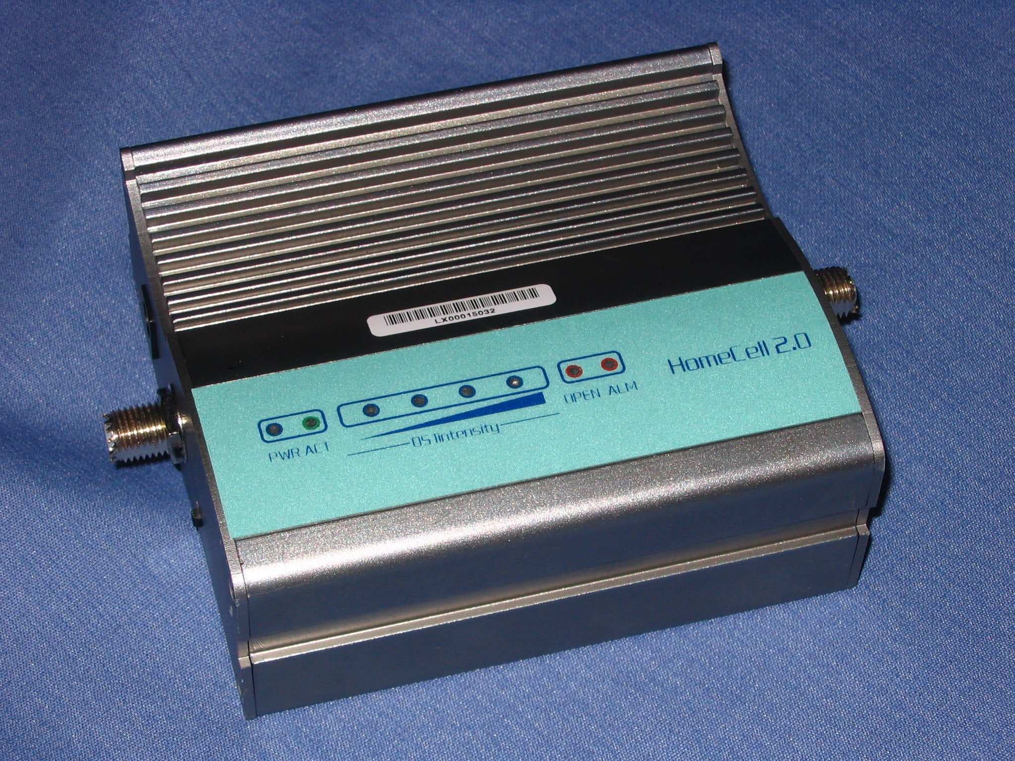
Click to zoom
Application Details
- Equipment Class
- PCB - PCS Licensed Transmitter
- Date of Grant
- Apr 30, 2007
- Application Purpose
- Original Equipment
- Date of Application
- Apr 29, 2007
- Equipment Note
- Celluar Amplifier
- Frequency Range
- 1930.00000000 - 1990.00000000
- Company
- HomeCell, LLC
- Country
- United States
Documents & Files
Document Text
Text extracted from the exhibit documents filed with the FCC. Open a document above to read the original.
Users Manual
HomeCell 2.0 Users Manual 1 HomeCellHomeCell 1.0 Overview HomeCell 2.0 brings you cell service were little, sporadic or no cell service exists due to physical signal blockage. If you are one of the millions that need to walk outside, go upstairs, or lean up against a window to get cellular signal in your own home then HomeCell is the product for you. Unlike other “booster” products HomeCell works with all cell phone providers with the exception if iDEN “walkie talkie” service. is a dual frequency bi-directional amplifier for the purpose of boosting “cellular” signals to create coverage where poor or now coverage exists. An omni directional antenna is mounted where good signal exists and a cable is connected between this antenna and HomeCell, the amplifier. The amplifier amplifies the signal it receives from the antenna, amplifies it and retransmits the signal in the area of the HomeCell amplifier. Conversely the cellular telephone signal in the immediate area of HomeCell is received by the amplifier and distributed back to the local cell tower through the cable and the antenna outside the residence. In addition, HomeCell is capable of performing in both “cellular” bands. These are the 800 MHz “Cellular” band and the 1800 MHz “PCS” bands. This allows for HomeCell to be transparent to the customer’s cellular usage. 2.0 Package Contents HomeCell 2.0 comes with everything you need to install the unit and start getting better service in your home including: - Outdoor antenna - Outdoor antenna mounting hardware - 30 feet of pre-connecteoized cable - HomeCell 2.0 bi-directional dual band amplifier 2 - Indoor antenna - AC/DC adapter An additional 30 foot piece of pre-conectorized extension cable is also available if required for installation. 3.0 Installation 3.1 Outdoor Antenna Installation. Choose a location for the outside antenna where you know you get good cellular signal. You can use the “signal level bars” on your phone or if you know where you get good service from experience to determine the location. Generally the higher above the ground the antenna installation the better the signal will be. The antenna can also be mounted in the attic of your home. Remember, you will need to think about the outside location with respect to the inside amplifier location. Remember that you are going to have to install a 30 foot cable between the two locations. Install the antenna with the hardware included. The antenna should be mounted vertically. 3 3.2 Indoor HomeCell Location Choose a central location in your home where the signal is the worse to locate the HomeCell amplifier. You can find this place by using the “signal level bars” on your cell phone or if you know from experience where the dead zones are. Pick a location centralized to the dead zones and within 30 feet of the outside antenna location. There also needs to be a power outlet close in order to power HomeCell with the AC/DC adapter included. Be sure HomeCell is “off” before connecting the AC/DC adapter and the cable. 3.3 Cable Installation The 30 pre-connectorized cable included needs to be installed between the outdoor antenna and the HomeCell amplifier. The connectors on the cable are different so that one matches the outside antenna and one matches the HomeCell amplifier. Most likely a drill will have to be used to run the cable through a wall or floor. Be sure the cable is attached to HomeCell before turing the power on. 3.4 HomeCell Installation HomeCell should be place in a table or shelf. Be sure the power is off. Connect the pre-connectorized cable to HomeCell. Connect the indoor antenna to HomeCell. Connect power to HomeCell and turn on the power switch. YOU CAN NOW MAKE CELL CALLS WHERE YOU NEVER HAVE BEFORE ! 4.0 Troubleshooting 4.1 HomeCell does not work with iDEN services like Nextel. 4.2 The antenna connected to HomeCell can be rotated and it’s position changed in order to maximize coverage in the home. 4.3 There must be separation between the outdoor antenna and HomeCell. If there is not enough separation the error light will turn red on HomeCell. Move the two antennas further apart, or change the relative elevations of the two antennas. 4.4 If the cell phone you are using is too close to the HomeCell unit the red error light will come on. Move away from the unit. 4.5 When a call is detected the ACT (active) light will flicker. 4.6 There are “signal bars” on the device that show the outside antenna reception signal. 4 5.0 Specifications 5.1 Frequency of operations i. “cellular” uplink 824-849 MHz, downlink 869-8955 MHz ii. “pcs” uplink 1850-1910 MHz, downlink 1930-1990 MHz b. System Compatibility i. AMPS, GPRS, TDMA, PCS, CDMA, GSM850, GSM1900 c. Maximum Output Power i. 824-849 MHz – 3 Watts ii. 1850-1910 MHz – 2 Watts d. Power i. AC input power – 100-120 VAC ii. 5 VDC, 1.5 A FCC Information This equipment has been tested and found to comply with the limits of a Class B digital device, pursuant to Part 15 of the FCC Rules. These limits are designed to provide reasonable protection against harmful interference in the residential installation. This equipment generates, uses and can radiate radio frequency energy and, if not installed and used in accordance with the instructions, may cause harmful interference to radio communications. However, there is no guarantee that interference will not occur in a particular installation. If this equipment does cause harmful interference to radio or television reception, which can be determined by turning off the equipment, the user is encouraged to try and correct the interference by one or more of the following measures: - Reorient or relocate the receiving antenna - Increase the separation between the equipment and receiver - Connect to the equipment to a different power outlet and a different circuit than the receiver. - Consult technical assistance or and electricians help. Technical Support Go to technical support at www.Home_Cell.com 5 Limited Warranty HomeCell, LLC, warrants yo…
Text truncated - open the document above for the full version.
Cover Letter(s)
HomeCellHomeCell January 31, 2007 Federal Communications Commission 7435 Oakland Mills Road Columbia, MD 21046 Subject: Initial submittal for certification and request for FCC to withhold schematic diagrams from public disclosure. Applicant: HomeCell, LLC Product: Cellular Amplifier Model: HomeCell 2.0 FCC Registration Number: 0012972204 Dear Sir/Madam: HomeCell, LLC respectfully submits the following information as submittal for certification HomeCell 2.0 under FCC Parts 47 CFR 2.925, 2.907, 2.1033. Also, HomeCell, LLC respectfully request that the submitted schematic diagrams be withheld from public disclosure. If you have any questions please contact me at 828/464-9012 or [email protected]. Sincerely, John C. Chamberlain
External Photos
Front/Right Side Front/Left Side Front Side
ID Label/Location Info
HomeCellHomeCell Model HomeCell 2.0 Serial # 0001 FCC ID U3FHOMECELL20 www.homecell.com This device complies with Part 15 of the FCC rules. Operation is subject to subject to the following two conditions: (1) this device may not use cause harmful interference and (2) this device must accept any interference received, including interference that may cause undesired operation.
Internal Photos
Boards in Chassis/ Left Side Boards in Chassis/ Right Side Boards Inserted into Chassis RF Board & Indicator Board RF Board – Side A RF Board – Side B Indicator Board – Side A Indicator Board – Side B
Operational Description
HomeCell 2.0 Dual Frequency Bi-Directional Amplifier Theory of Operation 1.0 Overview HomeCell 2.0 is a dual frequency bi-directional amplifier for the purpose of boosting “cellular” signals to create coverage where poor or now coverage exists. An omni directional antenna is mounted where good signal exists and a cable is connected between this antenna and HomeCell, the amplifier. The amplifier amplifies the signal it receives from the antenna, amplifies it and retransmits the signal in the area of the HomeCell amplifier. Conversely the cellular telephone signal in the immediate area of HomeCell is received by the amplifier and distributed back to the local cell tower through the cable and the antenna outside the residence. In addition, HomeCell is capable of performing in both “cellular” bands. These are the 800 MHz “Cellular” band and the 1800 MHz “PCS” bands. This allows for HomeCell to be transparent to the customer’s cellular usage. 2.0 Operational Specifications HomeCell 2.0 is a bi-directional dual band RF amplifier. “Uplink” is defined as HomeCell transmitting amplified cell phone hand set information to the wireless service provider, “Downlink is defined as the signal from the cellular or wireless provider received by HomeCell and redistributed in the “non-service” area. The two “bands” are: 1) The traditional “cellular band”, (uplink 824-849 MHz), (downlink 869-894 MHz), and 2) The traditional “PCS band”, (uplink 1850-1910 MHz), (downlink 1930-1990MHz) Signal protocol supported TDMA, CDMA, GSM850, GSM1900, AMPS, GPRS, and PCS. The maximum output power of the Cellular Band Uplink is 3 watts. The maximum output power of the PCS Band Uplink is 2 watts. Uplink maximum gain in both bands is 55 dB. Downlink maximum gain in both bands is 60 dB. DC Power is supplied via an AC converter with 5 volt/max 1 amp output to connector J7. 3.0 Internal Operation Downlink Circuitry - Input to the downlink circuitry starts at the BNC connector J6 per the schematic diagram. The two bands are then separated through a duplexer and each band subsequently passes through another duplexer to separate the transmit form the receive bands. The downlink signal is then processed through a series of band pass filters and amplifiers to give the desired output. The amplified downlink signal is then re-coupled to the uplink signal and the other band respectively and presented at the into antenna connector J5. Uplink Circuitry – Input to the uplink circuitry is the reverse path of the downlink circuitry. Input to the uplink circuitry starts at the connector J5. The two bands are then separated through a duplexer and each band subsequently passes through another duplexer to separate the transmit form the receive bands. The uplink signal is then processed through a series of band pass filters and amplifiers to give the desired output. The last amplifier stage is a feedback controlled amplifier that maintains signal output to the required 3 watts for the “cellular” band and 2 watts for the “PCS” band . The amplified uplink signal is then re-coupled to the downlink signal and the other band respectively and presented at the into antenna connector J6.
Parts List/Tune Up Info
Comment Pattern Quantity Components B4224 B4224 10 A23, A25, A30, A32, A34, A35, A36, A37, A38, A39 BPF B7759 DCS4D 5 A10, A14, A15, A17, A18 BPF CER0059A CER0059A 4 A5, A6, A7, A8 CER0111A CER0111A 2 A12, A20 CON2 SIP2 1 J10 CON3 SIP3 1 J8 CON4 SIP4 1 J9 CON5 SIP5 1 J1 CON5 SIP5 1 J2 LTF2012D LTF2012D 5 A4, A11, A19, A21, A24 MINI-UHF linker SMA-NEW 2 J5, J6 RF Amplifier MNA-5 DQ849 11 A1, A2, A3, A9, A13, A16, A26, A27, A2 9, A31, A33 Power socket PWR2.5 KLD-0202 1 J7 RF Amplifier RF3108 RF3108 1 A22 Detector SMS7630 SOD-123 3 D1, D2, D3 Operation Amplifier TLC272C SO-8 2 U1, U2 MCU LPC915 TSSOP14 1 A28 Capacitance CC41-0402-0.1uF±5% 402 2 C20, C24 Capacitance CC41-0603-0.1uF±5% 603 3 C27, C33, C44 Capacitance CC41-0603-1000PF±5% 603 18 C1, C2, C5, C8, C10, C11, C13, C15, C18, C19, C22, C25, C30, C31, C34, C40, C42, C46 Capacitance CC41-0603-100PF±5% 603 14 C3, C4, C6, C7, C9, C12, C1 4, C17, C29, C32, C36, C41, C47, C48 Capacitance CC41-0603-1uF±5% 603 1 C21 Capacitance CC41-0805-0.1uF±5% 805 2 C37, C49 Capacitance CC41-0805-100PF±5% 805 1 C26 Volatile Resistanceistance 5K 3266 1 VR1 Power switch SW-L 1 S1 Resistance RI11-0402-1/32W-18Ω±5% 402 2 R3, R31 Resistance RI11-0402-1/32W-1KΩ±5% 402 2 R20, R23 Resistance RI11-0402-1/32W-300Ω±5% 402 5 R2, R4, R19, R34, R35 Resistance RI11-0402-1/32W-43Ω±5% 402 2 R16, R24 Resistance RI11-0603-1/16W-110Ω±5% 603 2 R17, R22 Resistance RI11-0603-1/16W-180Ω±5% 603 1 R28 Resistance RI11-0603-1/16W-1KΩ±5% 603 20 R12, R13, R14, R18, R27, R29, R30, R32, R38, R39, R47, R49, R55, R56, R57, R58, R59, R6 0, R61, R62 Resistance RI11-0603-1/16W-220Ω±5% 603 2 R40, R48 Resistance RI11-0603-1/16W-33Ω±5% 603 11 R5, R6, R7, R9, R10, R11 , R36, R37, R42, R43, R44 Resistance RI11-0603-1/16W-51Ω±5% 603 13 R1, R8, R15, R26, R33, R 41, R45, R46, R50, R51, R52, R53, R54 Aluminium Electro Capacitance 1000uF/10V RB.1/.2 2 C38, C39 Transistor B35 SOT-23 3 Q1, Q2, Q3 Ta Electro Capacitance 10uF/10V 3216 2 C43, C45 Ta Electro Capacitance 33uF/10V 3528 4 C16, C23, C28, C35 LM1117T SOT-223 1 U3 Bill of Material for HomeCell 2.0
RF Exposure Info
MAXIMUM PERMISSIBLE EXPOSURE (MPE) CALCULATIONS The § 1.1310 Radiofrequency radiation exposure limits are listed in the table below. Frequency Range (MHz) Power Density Limit (mW/cm 2 ) 0.3-3.0 100 3.0-30 900/ Frequency2 30-300 1.0 300-1500 Frequency/300 Limits for Occupational/Controlled Exposures 1500-100,000 5.0 0.3-1.34 100 1.34-30 180/Frequency2 30-300 0.2 300-1500 Frequency/1500 Limits for General Population/Uncontrolled Exposure 1500-100,000 1.0 Calculations The radiated RF power (calculated using the stated antenna gain and the measured conducted output power) was used to calculate the maximum RF exposure at a 20 cm distance using the formula: Maximum RF Exposure at 20cm = (EIRP in mW)/(4Pi(20cm) 2 ) Cell Band: The maximum measured radiated power for the cell band was 28.86 dBm. In order to convert to EIRP a 2.15dB factor is added to the ERP to get 31.01 dBm or 1260 mW (Isotropic). Substituting this into the equation above, we get a Maximum RF Exposure (MPE) at 20cm of: MPE at 20cm = 1260 mW / (4Pi(20cm) 2 ) MPE at 20cm = 0.25 mW/cm 2 PCS Band: The maximum measured radiated power for the PCS band was 16.5 dBm or 44.7 mW. For the PCS band, there is no need to apply the 2.15dB factor to convert to EIRP since the measured radiated power is already in reference to an isotropic radiator. Substituting 44.7mW into the equation above, we get a Maximum RF Exposure (MPE) at 20cm of: MPE at 20cm = 44.7mW / (4Pi(20cm) 2 ) MPE at 20cm = 0.0089mW/cm 2 Test Results The worst case MPE at 20cm of 0.25mW/cm 2 is much less than the 0.565 mW/cm 2 limit for general population/uncontrolled exposure shown in the table above for the cell band. For the PCS band, the worst case MPE at 20cm of 0.0089mW/cm 2 is much less than the 1.0 mW/cm 2 limit.
Test Report
This report is for the exclusive use of Intertek's Client and is provided pursuant to the agreement between Intertek and its Client. Intertek's responsibility and liability are limited to the terms and conditions of the agreement. Intertek assumes no liability to any party, other than to the Client in accordance with the agreement, for any loss, expense or damage occasioned by the use of this report. Only the Client is authorized to copy or distribute this report and then only in its entirety. Any use of the Intertek name or one of its marks for the sale or advertisement of the tested material, product or service must first be approved in writing by Intertek. The observations and test results in this report are relevant only to the sample tested. This report by itself does not imply that the material, product, or service is or has ever been under an Intertek certification program. TEST REPORT Report Number: 3108903LEX001 Project Number: 3108903 Evaluation of the Cellular Amplifier Model Number: HomeCell 2.0 FCC ID: U3FHOMECELL20 FCC Part 22 Subpart H FCC Part 24 Subpart E For HomeCell, LLC Test Performed by: Test Authorized by: Intertek 731 Enterprise Drive Lexington, KY 40510 HomeCell, LLC 1699 Poe Circle Hickory, NC 28601 Prepared By:_______________________________Date:____1/15/2007________ Jason Centers, Senior Project Engineer Approved By:______________________________Date:____1/15/2007_________ Bryan C. Taylor, EMC Team Leader Intertek 731 Enterprise Drive, Lexington, KY 40510 Telephone: 859-226-1000 Fax: 859-226-1040 Web: www.etlsemko.com 731 Enterprise Drive, Lexington KY 40510 Evaluation For:HomeCell, LLC FCC ID: U3FHOMECELL20 Model Number: HomeCell 2.0 Report Number: 3108903LEX001 Page 2 of 67 FCC Part 22H and 24E Evaluation TABLE OF CONTENTS 1 JOB DESCRIPTION .......................................................................................................................... 3 1.1 COMPANY INFORMATION............................................................................................................ 3 1.2 TEST SAMPLE INFORMATION....................................................................................................... 3 1.3 SYSTEM SUPPORT EQUIPMENT.................................................................................................... 4 1.4 CABLES USED DURING TESTING................................................................................................. 4 1.5 SYSTEM BLOCK DIAGRAM(S) ...................................................................................................... 5 1.6 MODE(S) OF OPERATION / ENGINEERING JUDGMENTS................................................................ 6 2 EXECUTIVE SUMMARY................................................................................................................. 7 2.1 MODIFICATIONS REQUIRED FOR COMPLIANCE............................................................................ 7 3 TEST FACILITY................................................................................................................................ 8 3.1 TEST EQUIPMENT......................................................................................................................... 8 4 CONDUCTED RF POWER .............................................................................................................. 9 4.1 TEST PROCEDURE........................................................................................................................ 9 4.2 TEST RESULTS............................................................................................................................. 9 5 RADIATED RF POWER................................................................................................................. 12 5.1 TEST PROCEDURE...................................................................................................................... 12 5.2 TEST RESULTS........................................................................................................................... 12 6 MAXIMUM PERMISSIBLE EXPOSURE (MPE) CALCULATIONS ...................................... 15 6.1 CALCULATIONS.......................................................................................................................... 15 6.2 TEST RESULTS........................................................................................................................... 15 7 EMISSION LIMITATIONS, OCCUPIED BANDWIDTH, INPUT/OUTPUT BANDWIDTH COMPARISON......................................................................................................................................... 16 7.1 TEST PROCEDURE...................................................................................................................... 16 7.2 TEST RESULTS........................................................................................................................... 16 8 OUT OF BAND EMISSION AT ANTENNA TERMINALS & INTERMODULATION ATTENUATION....................................................................................................................................... 31 8.1 TEST PROCEDURE...................................................................................................................... 31 8.2 TEST RESULTS........................................................................................................................... 32 9 FIELD STRENGTH OF SPURIOUS RADIATION ..................................................................... 66 9.1 TEST PROCEDURE...................................................................................................................... 66 9.2 TEST RESULTS........................................................................................................................... 66 731 Enterprise Drive, Lexington KY 40510 Evaluation For:HomeCell, LLC FCC ID: U3FHOMECELL20 Model Number: HomeCell 2.0 Report Number: 3108903LEX001 Pa…
Text truncated - open the document above for the full version.
Test Setup Photos
Radiated Test Configuration - Front Radiated Test Configuration - Back Conducted Test Configuration
Contact Information
Applicant
John Charles Chamberlain(President)
Technical Contact
HomeCell LLCJohn C Chamberlain
[email protected]828-256-6191
1699 Poe Circle · Hickory, North Carolina · United States
Test Firm
Intertek Testing Services NA Inc.Charles Parker
Technical Specifications
| # | Rule Parts | Frequency Range | Power Output | Emission | Tolerance |
|---|---|---|---|---|---|
| 14 | 24E | 1.93 GHz - 1.99 GHz | 11.70 mW | DXW | Amp |