U47LIVE20TRBROADCAST RADIO
AEQ Broadcast International, Inc.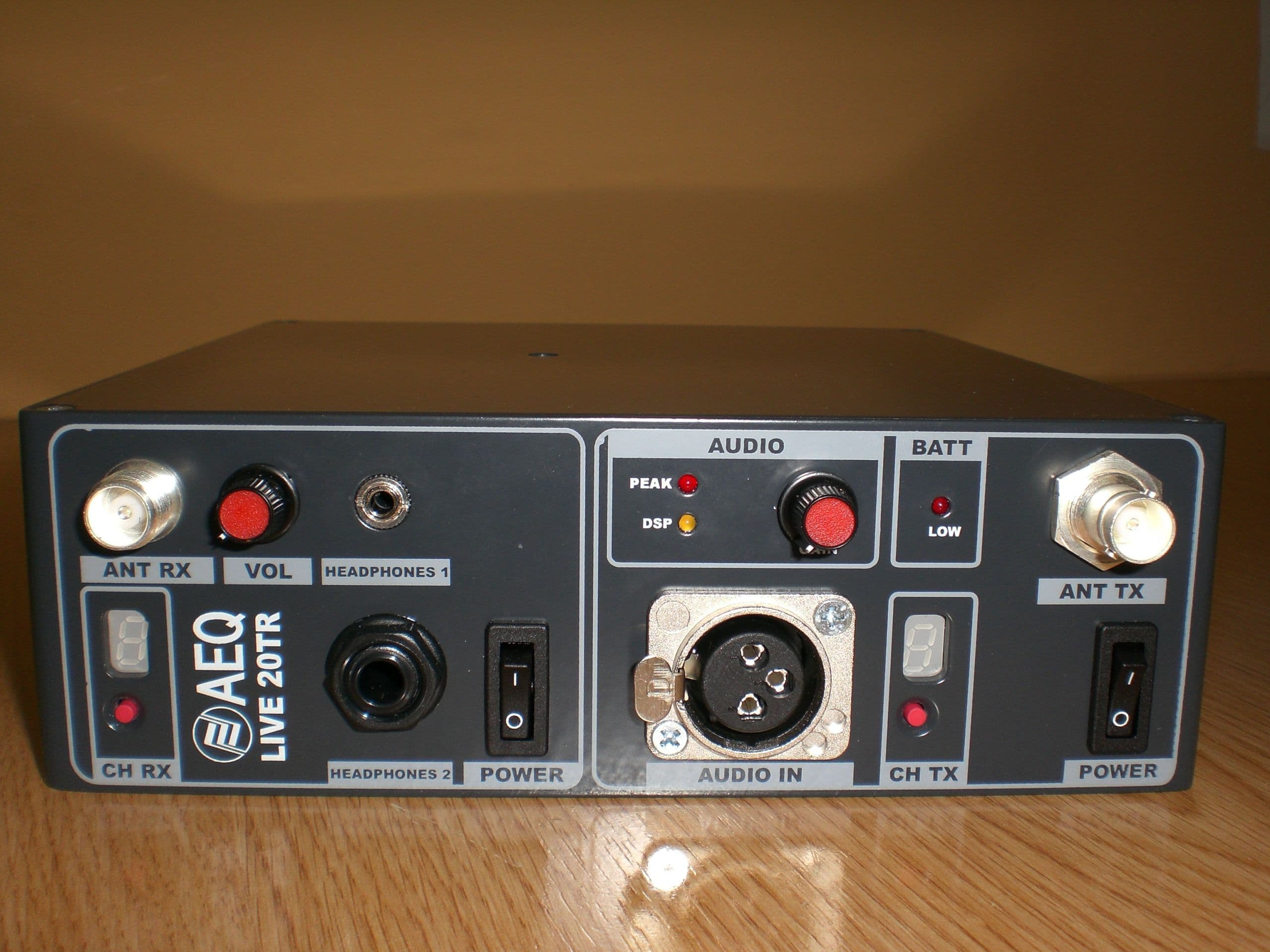
Click to zoom
Application Details
- Equipment Class
- TNB - Licensed Non-Broadcast Station Transmitter
- Date of Grant
- May 30, 2007
- Application Purpose
- Original Equipment
- Date of Application
- May 28, 2007
- Equipment Note
- BROADCAST RADIO
- Frequency Range
- 166.25000000 - 170.50000000
- Country
- United States
Documents & Files
Document Text
Text extracted from the exhibit documents filed with the FCC. Open a document above to read the original.
Users Manual
AEQ LIVE 20 TR . USER MANUAL ED 05/07 AEQ LIVE 20 TR . 2 LIVE 20 TR USER’S MANUAL 1. LIVE 20 TR General description 1.1 General Description 1.2 Construction 1.3 Front panel description 1.4 FCC Compliance 1.5 Warning to Users 2. LIVE 20 TR Hardware description 2.1 On/Off Switch 2.2 Display and channel selector 2.3 Audio input 2.4 TX Antenna connector 2.5 Low battery indicator 2.6 Audio level adjustment 2.7 Peak audio indicator 2.8 Power supply 2.9 Other connectors 3. LIVE 20TR Technical specifications 3.1 Technical characteristics 3.2 Mechanical specifications 4. ACCESORIES 5. CH-20 BATTERY CHARGER 5.1 General description 5.2 Front and rear view 5.3 Connection and starting to work 5.4 Indications 5.5 Characteristics 5.6 Protections 5.7 Connectors pin-outs ANNEX 1 – Connector pin-out ANNEX 2 – Security recommendations A.E.Q. Warranty AEQ LIVE 20 TR . 3 1. LIVE 20 TR GENERAL DESCRIPTION 1.1 LIVE 20 TR GENERAL DESCRIPTION The AEQ LIVE 20 TR is a high specification FM transmitter for portable and mobile service. The signal generators together with the RF output module and the audio processor forms a high quality transmitter capable of faithfully broadcasting work in any situation. Transmit frequency are delivered in digital frequency synthesizers and allow the selection of up to 16 pre-programmed channels. The audio processor allows the use of dynamic microphones as well as line level sources. A mechanized aluminium enclosure assures outstanding mechanical stability and immunity to interference and crosstalk. In standard service the LIVE 20 TR is powered by a removable rechargeable battery pack, which can be recharged in the unit as well. Also supplied with the LIVE 20 TR is a ¼ wavelength centered antenna. A 9 pin sub-D connector in the left side of the unit allows external reprogramming. AEQ LIVE 20 TR . 4 1.2 CONSTRUCTION The boards of the AEQ LIVE 20 TR are made of epoxy glass fiber type FR4 with a thickness of 1,6 mm, 2 side type. The AEQ LIVE 20 TR is equipped with Surface Mounted Devices (SMD) that give the equipment a high grade of robustness. If one SMD is damaged, the defective component should be replaced with a new one. Do not sense unsoldered components, even if they seem to be faultless. AEQ LIVE 20 TR . 5 1.3 FRONT PANEL VIEW AUDIO PHONES 2CH RXCH TX PEAK LOW DSP ANT RX AUDIO IN ANT TX BAT POWERPOWER GAIN PHONES 1VOL OO 1123 4567 AEQ LIVE 20 TR . 6 1.- ON/OFF switch 2.- Display and channel selector 3.- Audio input 4.- Tx antenna connector 5.- Low battery indicator 6.- Audio level adjustment 7.- Peak audio indicator Note: The Rx section is not equipped 1.4 FCC Compliance This device complies with part 15 of the FCC rules. Operation is subject to the condition that this device does not cause harmful interface. Any changes or modifications not expressly approved by the party responsible for compliance could void the user’s authority to operate the equipment. 1.5 Warning to Users Changes or modifications not expressly approved by the party responsible for compliance could void the user’s authority to operate the equipment. AEQ LIVE 20 TR . 7 2. LIVE 20 TR HARDWARE 2.1 ON/OFF SWITCH To switch on the equipment you must act over the switch labelled POWER. When the “power” switch is activated, the internal microcontrollers will start executing some routines. Once the routines have been successfully executed, the equipment will provide the RF output power. Until the microcontrollers have finished with the verification of the PLLs locking, the equipment will not provide RF power to the output. The equipment will automatically start in the last selected channel. 2.2 DISPLAY AND CHANNEL SELECTOR The equipment is provided with a selector and an hexadecimal display in order to select the working frequencies. The display will show the selected channel in hexadecimal format (0 to F). The channel push button selector allows to the user to change the selected channel. It has a little action delay to prevent undesired frequency changes. If the user maintains the button pressed, then the channel display changes continuously. The 16 registries can only be changed by factory staff connecting a PC to the SUB-D(9p), located in one side of the equipment. The frequency range of each equipment is specific and is adjusted at the factory before shipment. AEQ LIVE 20 TR . 8 CHANNEL FREQUENCIES: CHANNEL FREQUENCY 0 161.00000 1 161.00625 2 161.01250 3 161.01875 4 161.02500 5 161.03125 6 161.03750 7 161.04375 8 161.05000 9 161.05625 A 161.06250 B 161.06875 C 161.07500 D 161.08125 E 161.08750 F 161.09375 2.3 AUDIO INPUT The audio input connector Is a XLR, 3 pin audio connector which allows the connection of any kind of balanced or unbalanced audio signal source with levels varying from MIC level to LINE level. 2.4 TX ANTENNA CONNECTOR The TX Antenna connector Is a BNC connector used to connect the proper antenna to the equipment. The user can choose to connect the antenna to the equipment directly or to connect an antenna with a cable. The output impedance of this port is 50 ohms. This port can be used as well to check the equipment specifications in a laboratory bench. 2.5 LOW BATTERY INDICATOR The low-battery indicator Is a red LED that shows the battery working status. If the red led stays dark, then the battery is still in good working conditions. AEQ LIVE 20 TR . 9 If the red led is lighting, then means that the approximate remaining work time is around 20 minutes. The decision to send the low battery message to the red light is taken by one of the inner microcontrollers. One ADC (Analog to Digital Converter) takes the battery voltage data and then the microcontroller takes the decision to turn on or not the red led. 2.6 AUDIO LEVEL ADJUSTMENT The audio GAIN selector is a multi-position switch that provides audio level adjustments for a wide variety of audio sources. Its associated set of precision resistors allows the user to select gain preset ranging from MIC level sources to LINE level sources. This fe…
Text truncated - open the document above for the full version.
ID Label/Location Info
Proposed Location – Side of DUT FCC ID: U47LIVE20TR This device complies with part 15 of the FCC rules. Operation is subject to the condition that this device does not cause harmful interface. Label Here
ID Label/Location Info
Proposed Location – Side of DUT FCC ID: U47LIVE20TR This device complies with part 15 of the FCC rules. Operation is subject to the condition that this device does not cause harmful interface. Label Here
Test Report
849 NW STATE ROAD 45 NEWBERRY, FL 32669 USA PH: 888.472.2424 OR 352.472.5500 FAX: 352.472.2030 EMAIL: [email protected] HTTP://WWW.TIMCOENGR.COM FCC PART 74 TEST REPORT Applicant AEQ Broadcast International Inc. Address 4121 SW 47 th Avenue, Ste 1303 Fort Lauderdale, FL 33314 USA FCC ID U47LIVE20TR MODEL NUMBER Live 20TR PRODUCT DESCRIPTION Low Power Auxiliary Broadcast Radio DATE SAMPLE RECEIVED February 27, 2007 DATE TESTED March 15, 2007 Tested By Joe Scoglio Approved By Mario de Aranzeta REPORT NO. 487UT7TestReport.pdf TEST RESULTS PASS FAIL THE ATTACHED REPORT SHALL NOT BE REPRODUCED EXCEPT IN FULL WITHOUT THE WRITTEN APPROVAL OF TIMCO ENGINEERING, INC. Certificate # 0955-01 TABLE OF CONTENTS ATTESTATION STATEMENT...............................................................................3 REPORT SUMMARY............................................................................................4 TEST ENVIRONMENT.........................................................................................4 TEST SETUP.......................................................................................................4 DEVICE UNDER TEST INFORMATION................................................................5 TEST EQUIPMENT LIST......................................................................................6 TEST PROCEDURE............................................................................................8 TEST RESULT..................................................................................................11 RF POWER OUTPUT.................................................................................................11 MODULATION CHARACTERISTICS...........................................................................12 OCCUPIED BANDWIDTH..........................................................................................16 SPURIOUS EMISSIONS AT ANTENNA TERMINALS (CONDUCTED)...........................18 FIELD STRENGH OF RADIATED SPURIOUS EMISSIONS..........................................19 FREQUENCY STABILITY...........................................................................................20 APPLICANT: AEQ International Inc. FCCID: U47LIVE20TR Report #: W:\A\AEQ\487UT7\487UT7TestReport.doc Page 2 of 20 ATTESTATION STATEMENT Certificate # 0955-01 This equipment has been tested in accordance with the standards identified in this test report. To the best of my knowledge and belief, these tests were performed using the measurement procedures described in this report and demonstrate that the equipment complies with the appropriate standards. All instrumentation and accessories used to test products for compliance to the indicated standards are calibrated regularly in accordance with ISO 17025 requirements. I attest that the necessary measurements were made, under my supervision, at TIMCO ENGINEERING, INC. located at 849 N.W. State Road 45, Newberry, Florida 32669. Authorized Signatory Name: Mario de Aranzeta Signature: On file Function: Engineer Date: 5/25/2007 Tester name: Nam Nguyen Date: 5/25/2007 APPLICANT: AEQ International Inc. FCCID: U47LIVE20TR Report #: W:\A\AEQ\487UT7\487UT7TestReport.doc Page 3 of 20 REPORT SUMMARY Disclaimer The test results relate only to the items tested. Report Purpose To demonstrate the DUT to comply with FCC Pt 74 and for a low power auxiliary broadcast radio Applicable Rule Part(s) Pt 74, Pt 15.209, ANSI C63.4: 2003, ANSI/TIA-603-C: 2004 Related Test Report Digital Portion Verified TEST ENVIRONMENT Test Facilities All required tests were performed by Timco Engineering Inc. that is located at 849 NW State Road 45 Newberry, FL 32669 Timco’s test facilities accreditation is on file with regulatory agencies. Test Conditions Temperature: 26ºC Relative Humidity: 50% TEST SETUP Deviation from the rules There was no deviation from the test standards. Modification to the DUT No modification was made to the DUT. Test Exercise (e.g. software description, test signal, etc.) The DUT was placed in continuous transmit mode of operation based upon the applicant’s instruction. Accessories tested with N/A. The DUT is a stand-alone device. Cable(s) Manufacturer supplied cables APPLICANT: AEQ International Inc. FCCID: U47LIVE20TR Report #: W:\A\AEQ\487UT7\487UT7TestReport.doc Page 4 of 20 DEVICE UNDER TEST INFORMATION DUT Description Low Power Auxiliary Broadcast Radio FCC ID U47LIVE20TR Model Name Live 20TR Operating Frequency 161.625 – 161.725 MHz Occupied Bandwidth 200 kHz Emission Designators F3E Calculation of Designators Bn = 2M + 2DK M=3000 Hz D=5000 Hz (Peak Deviation) K=1 Bn=2 (3000) + 2(5000) (1) = 16 kHz Modulation(s) FM User Power Range & Control There are NO user power controls DC Voltages and Current into Final Amplifier 3.0V Battery Vce = 2.9 V Ice = 28 mA Test Item Pre-Production Type of Equipment Fixed and Mobile APPLICANT: AEQ International Inc. FCCID: U47LIVE20TR Report #: W:\A\AEQ\487UT7\487UT7TestReport.doc Page 5 of 20 TEST EQUIPMENT LIST Device Manu. Model Serial Number Cal/Char Date Due Date 3/10-Meter OATS TEI N/A N/A Listed 3/27/04 3/26/07 3-Meter OATS TEI N/A N/A Listed 1/11/06 1/10/09 AC Voltmeter HP 400FL 2213A14499 CAL 12/29/06 12/29/08 Analyzer Blue Tower Quasi- Peak Adapter HP 85650A 2811A01279 CAL 4/13/05 4/13/07 Analyzer Blue Tower RF Preselector HP 85685A 2926A00983 CAL 9/5/05 9/5/07 Analyzer Blue Tower Spectrum Analyzer HP 8568B 2928A04729 2848A18049 CAL 4/13/05 4/13/07 Coaxial Cable #64 Semflex Inc. 60637 Timco #64 CHAR 11/28/05 11/28/07 Analyzer Open- Frame Tower Preamplifier HP 8449B 3008A01075 CAL 8/8/05 8/8/07 Analyzer Open- Frame Tower Quasi-Peak Adapter HP 85650A 2046A00305 CAL 8/8/05 8/8/07 Analyzer Open- Frame Tower RF Preselector HP 85685A 3107A01282 CAL 2/6/06 2/6/08 Analyzer Open- Frame Tower Spectrum Analyzer HP 8566B/85662A 2627A03154/2648A14276 CAL 8/8/05 8/8/07 Analyzer Silver Tower Quasi- Peak Adapter HP 85650A 3303A01844 CAL 10/30/06 10/30/08 Analyzer Silver Tower RF Preselector H…
Text truncated - open the document above for the full version.
Test Report
FCC PART 74 TEST REPORT Applicant AEQ Broadcast International Inc. Address 4121 SW 47 th Avenue, Ste 1303 Fort Lauderdale, FL 33314 USA FCC ID U47LIVE20TR MODEL NUMBER Live 20TR PRODUCT DESCRIPTION Low Power Auxiliary Broadcast Radio Remote Pickup Broadcast Radio DATE SAMPLE RECEIVED February 27, 2007 DATE TESTED March 15, 2007 Tested By Joe Scoglio Approved By Mario de Aranzeta REPORT NO. 487UT7TestReport.pdf TEST RESULTS PASS FAIL THE ATTACHED REPORT SHALL NOT BE REPRODUCED EXCEPT IN FULL WITHOUT THE WRITTEN APPROVAL OF TIMCO ENGINEERING, INC. 849 NW STATE ROAD 45 NEWBERRY, FL 32669 USA PH: 888.472.2424 OR 352.472.5500 FAX: 352.472.2030 EMAIL: [email protected] HTTP://WWW.TIMCOENGR.COM Certificate # 0955-01 APPLICANT: AEQ International Inc. FCCID: U47LIVE20TR Report #: W:\A\AEQ\487UT7\487UT7TestReport mario.doc Page 2 of 20 TABLE OF CONTENTS ATTESTATION STATEMENT ...............................................................................3 REPORT SUMMARY............................................................................................4 TEST ENVIRONMENT .........................................................................................4 TEST SETUP.......................................................................................................4 DEVICE UNDER TEST INFORMATION ................................................................5 TEST EQUIPMENT LIST......................................................................................6 TEST PROCEDURE ............................................................................................8 TEST RESULT ..................................................................................................10 RF POWER OUTPUT .................................................................................................10 MODULATION CHARACTERISTICS...........................................................................11 OCCUPIED BANDWIDTH..........................................................................................15 SPURIOUS EMISSIONS AT ANTENNA TERMINALS (CONDUCTED) ...........................17 FIELD STRENGH OF RADIATED SPURIOUS EMISSIONS..........................................19 FREQUENCY STABILITY...........................................................................................20 APPLICANT: AEQ International Inc. FCCID: U47LIVE20TR Report #: W:\A\AEQ\487UT7\487UT7TestReport mario.doc Page 3 of 20 ATTESTATION STATEMENT Certificate # 0955-01 This equipment has been tested in accordance with the standards identified in this test report. To the best of my knowledge and belief, these tests were performed using the measurement procedures described in this report and demonstrate that the equipment complies with the appropriate standards. All instrumentation and accessories used to test products for compliance to the indicated standards are calibrated regularly in accordance with ISO 17025 requirements. I attest that the necessary measurements were made, under my supervision, at TIMCO ENGINEERING, INC. located at 849 N.W. State Road 45, Newberry, Florida 32669. Authorized Signatory Name: Mario de Aranzeta Signature: On file Function: Engineer Date: 6/28/2007 Tester name: Nam Nguyen Date: 6/28/2007 APPLICANT: AEQ International Inc. FCCID: U47LIVE20TR Report #: W:\A\AEQ\487UT7\487UT7TestReport mario.doc Page 4 of 20 REPORT SUMMARY Disclaimer The test results relate only to the items tested. Report Purpose To demonstrate the DUT to comply with FCC Pt 74 and for a low power auxiliary broadcast radio and Remote Pickup Broadcast Service Applicable Rule Part(s) Pt 74, Pt 15.209, ANSI C63.4: 2003, ANSI/TIA-603-C: 2004 Related Test Report Digital Portion Verified TEST ENVIRONMENT Test Facilities All required tests were performed by Timco Engineering Inc. that is located at 849 NW State Road 45 Newberry, FL 32669 Timco’s test facilities accreditation is on file with regulatory agencies. Test Conditions Temperature: 26ºC Relative Humidity: 50% TEST SETUP Deviation from the rules There was no deviation from the test standards. Modification to the DUT No modification was made to the DUT. Test Exercise (e.g. software description, test signal, etc.) The DUT was placed in continuous transmit mode of operation based upon the applicant’s instruction. Accessories tested with N/A. The DUT is a stand-alone device. Cable(s) Manufacturer supplied cables APPLICANT: AEQ International Inc. FCCID: U47LIVE20TR Report #: W:\A\AEQ\487UT7\487UT7TestReport mario.doc Page 5 of 20 DEVICE UNDER TEST INFORMATION DUT Description Low Power Auxiliary Broadcast Radio Remote Pickup Broadcast Service FCC ID U47LIVE20TR Model Name Live 20TR Emission Designators F3E Calculation of Designators Bn = 2M + 2DK M=3000 Hz D=5000 Hz (Peak Deviation) K=1 Bn=2 (3000) + 2(5000) (1) = 16 kHz Bn = 2M + 2DK M=3000 Hz D=2500 Hz (Peak Deviation) K=1 Bn=2 (3000) + 2(2500) (1) = 11 kHz Modulation(s) FM User Power Range & Control There are NO user power controls DC Voltages and Current into Final Amplifier 11.0V Battery Vce = 10.9 V Ice = 350 mA Test Item Pre-Production Type of Equipment Fixed, Mobile, and Portable APPLICANT: AEQ International Inc. FCCID: U47LIVE20TR Report #: W:\A\AEQ\487UT7\487UT7TestReport mario.doc Page 6 of 20 TEST EQUIPMENT LIST Device Manu. Model Serial Number Cal/Char Date Due Date 3/10-Meter OATS TEI N/A N/A Listed 3/27/04 3/26/07 3-Meter OATS TEI N/A N/A Listed 1/11/06 1/10/09 AC Voltmeter HP 400FL 2213A14499 CAL 12/29/06 12/29/08 Analyzer Blue Tower Quasi- Peak Adapter HP 85650A 2811A01279 CAL 4/13/05 4/13/07 Analyzer Blue Tower RF Preselector HP 85685A 2926A00983 CAL 9/5/05 9/5/07 Analyzer Blue Tower Spectrum Analyzer HP 8568B 2928A04729 2848A18049 CAL 4/13/05 4/13/07 Coaxial Cable #64 Semflex Inc. 60637 Timco #64 CHAR 11/28/05 11/28/07 Analyzer Open- Frame Tower Preamplifier HP 8449B 3008A01075 CAL 8/8/05 8/8/07 Analyzer Open- Frame Tower Quasi-Peak Adapter HP 85650A 2046A00305 CAL 8/8/05 8/8/07 Analyzer Open- Frame T…
Text truncated - open the document above for the full version.
Test Setup Photos
Test Setup Photo
Contact Information
Applicant
Gerardo Vargas(Manager)
Test Firm
Timco Engineering, Inc.Sid Sanders
Technical Specifications
| # | Rule Parts | Frequency Range | Power Output | Emission | Tolerance |
|---|---|---|---|---|---|
| 5 | 74 | 166.25 MHz - 170.5 MHz | 2.5 W | 11K0F3E | 2 ppm |