U56-CN-CX312INTELLIGENT BATTERY GUARD
ZHUHAI CHENNAN ENTERPRISE CO., LTD.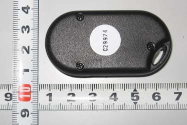
Click to zoom
Application Details
- Equipment Class
- DXX - Part 15 Low Power Communication Device Transmitter
- Date of Grant
- Mar 28, 2007
- Application Purpose
- Original Equipment
- Date of Application
- Mar 28, 2007
- Equipment Note
- INTELLIGENT BATTERY GUARD
- Frequency Range
- 433.85000000 - 433.95000000
- Country
- China
Documents & Files
Document Text
Text extracted from the exhibit documents filed with the FCC. Open a document above to read the original.
Users Manual
Warnings & Safety Information • Whenever you work with a lead-acid ba tter y , someone should al ways be within range of your voice or c lose enough to come to your aid. • W ear eye protection and proper c lothing. Avoid touching your eyes while working with a lead-acid ba tter y . • Ha ve plenty of fresh wa ter and soa p nearby in case ba tter y acid comes into contact with skin, c lothing, or eyes. • If ba tter y acid comes into contact with skin or c lothing, wash the area immedia tely with soa p and wa ter . Seek medical a ttention if irrita tion or pain develops and persists after washing. If acid enters the eyes, fl ush with cold running wa ter for a t least 10 minutes, and seek medical a ttention immedia tely . • Do not smoke, use ma tches or a cigarette lighter , or allo w a spark or fl ame near a ba tter y . • Do not allo w metal to come into contact with the ba tter y posts. It may spark or short-circuit the ba tter y , and may cause an explosion. • Remove rings, bracelets, necklaces, and wa tches when working with a lead-acid ba tter y . • Ba tter y posts, terminals, and rela ted accessories contain lead and lead compounds. W a sh your hands after handling. Features & Specifications NO TE: It is strongly recommended to review the installation instructions in their entirety in order to ensure a full understanding of the operation and installation of the Intelligent Batter y Guard. INTELLIGENT BATTERY GUARD The Intelligent Ba tter y Guard is an innova tive accessor y tha t easily installs onto an y 12 V ba tter y . It protects the driver from getting stranded with a dead ba tter y , and protects the vehic le a gainst theft. Using unique micro-electronic technolog y , the Intelligent Ba tter y Guard continually monitors the ba tter y charge, and automa tically isola tes the ba tter y from the electrical system if it detects tha t the po wer is falling belo w the level tha t is required to start the engine. This ensures tha t there is al ways enough po wer to start the engine. The Intelligent Ba tter y Guard also acts as an anti-theft system. Technical Specifications DIMENSIONS Base: 2 1/4 x 2 3/4” (5.8 x 7.2 cm ) Height: 2” (5.3 cm ) Brackets: 1 1/4 x 5/8 x 1/8” (3.2 cm x 1.5 cm x 3 mm ) WEIGHT Intelligent Ba tter y Guard: 8 1/2 oz (245 g ) Remote control unit: 3/5 oz (18.2 g ) Accessories: 5 1/2 oz (159 g ) P acka ging: 7 1/2 oz (212 g ) T otal weight: 24 1/4 oz (687.2 g ) POWER CONSUMPTION Normal opera tion mode: 10 mA Current dra wn for ignition: up to 1100 A Current dra wn under normal opera ting conditions: 250 A OPERATIONAL TEMPERATURE RANGE: -60 to 200°F (-51 to 90°C); the Intelligent Ba tter y Guard is made from non-combustible ma terials. Package Contents: INTELLIGENT BATTERY GUARD UNIT 1. P ositive (+) side of Intelligent Ba tter y Guard with Butterfl y Connector 2. Black Ground Wire 3. White Antenna Wire 4. Manual reset s witch 5. Buzzer REMOTE CONTROL UNIT (X2) NO TE: The ba tteries provided in the accessor y kit must be installed. 2-Year Warranty What does this warranty co ver? This product is manufactured from parts and components tha t are new or equivalent to new , in accordance with industr y standard practices. This warranty covers an y defects in workmanship or ma terials. How long does co verage last ? This warranty lasts for 2 years from the da te of purchase . What does this warranty not co ver ? This warranty will not a pply where the product has been misused, neglected, improperly installed, physically dama ged or altered , either internally or externally , or dama ged from improper use or use in an unsuitable environment. What will we do? Motomaster® Canada will, a t its option, repair or replace the defective product free of charge. Motomaster® Canada will, a t its o wn option, use new and/or reconditioned parts made by various manufacturers in performing warranty repair and building replacement products. If Motomaster® Canada repairs or replaces a product, its warranty term is not extended. Motomaster® Canada o wns all parts removed from repaired products. How do you get ser vice? T o qualify for the warranty , da ted proof of purchase must be provided and the product must not ha ve been disassembled or modifi ed without prior authoriza tion. If your product requires warranty ser vice, please return it to the place of purchase along with a copy of your da ted proof of purchase. Installation Instructions TOOLS REQUIRED: Open-end 17 mm or adjustable wrench, standard and Phillips The positive ba tter y post is ta pered. V e rify tha t the cable is screwdrivers mounted correctly . NO TE: Before beginning installa tion, verify tha t the ba tter y is able to hold a proper charge. Check using a voltmeter or consult a qualifi ed technician. If the ba tter y is not able to hold a minimum charge, it may be a t the end of its life c y c le. NO TE: After installa tion, verify tha t all connections are tight. NO TE: Instruction stickers ha ve been added to several key connection points in order to assist with installa tion. STEP 1: Disconnecting the Ba tter y Cables: A. Disconnect the black/nega tive (–) cable from the nega tive (–) post/bolt on the ba tter y . The positive cable must not come into contact with the ACC c lip. B. Disconnect the red/positive (+) cable from the positive (+) post/bolt on the ba tter y . STEP 2: Connecting the Intelligent Ba tter y Guard: A. Connect the positive (+) c lamp on the positive (+) side of the Intelligent Ba tter y Guard to the positive (+) post/bolt on the ba tter y . NO TE: The positive (+) c lamp of the Intelligent Ba tter y Guard is loca ted on the side of the unit tha t has 12 V + printed on it. CONFIGURATION OPTIONS Ba tter y loca tion and position differ depending on the vehic le, The Intelligent Ba tter y Guard can be confi gured for various top mounting, side mounting, and chassis mounting installa tions (see belo w). Top Mounting Options Chassis Mounting Option Side Mounting Options STEP 3: TOP & SIDE MOUNTING OPTION…
Text truncated - open the document above for the full version.
Block Diagram
Block Diagram (433.9MHz)
Cover Letter(s)
深圳市博顿电子技术服务有限公司 Bontek Compliance Laboratory Ltd 深圳市福田区竹子林紫竹六路金民大厦802-804 Rm 802~804, Jinmin Bld., Zizhu 6 th Rd., Zhuzhi Lin, Futian, Shenzhen 518040, Guangdong, P. R. China Tel: 86-755-82871080 Fax: 86-755-82871368 Http:/ / www.bontek.com.cn DATE: March 29, 2007. Dear TCB Section of Timco Engineering, Inc., Thank you for cooperation. I would like to submit FCC application of ZHUHAI CHENNAN ENTERPRISE CO.,LTD /FCCID: U56-CN-CX312 by your TCB Approval today. Best Regards, Bontek compliance Laboratory Ltd. Tony Wu EMC Engineer
External Photos
External Photographs
ID Label/Location Info
FCC ID Label Sample for FCCID: U56-CN-CX312 FCCID: U56-CN-CX312
Internal Photos
Internal Photographs
Operational Description
DESCRIPTION OF OPERATION The encoder generates a digital code serially transmit (typical designation) when press any button into the Central Processor Unit (modulator or called as mixer) stage in circuit. The serially digital signal mixed with the carrier at modulator (mixer) stage by way of FSK mode (Frequency Modulation) and to the Transmitter antenna. The modulation depth is designed such as ± 5KHz in this application, that means the pulse (may be at high level state or low level state) will trigger the oscillator to generate a frequency at a specified fundamental frequency +5KHz or −5KHz, depended on the designation. For example, if the carrier frequency defined as fundamental frequency +5KHz at high level state, then the alternative carrier frequency will be fundamental frequency −5KHz at low level state. The Central Processor will trigger the oscillator to generate a carrier frequency when receive the signal. The encoder generates a pulse code serially transmit (typical designation) when press any button into the Central Processor Unit (modulator or called as mixer) stage in circuit. The pulse signal mixed with the carrier at modulator (mixer) stage by way of Pulse Modulation and to the Transmitter antenna. The Central Processor will trigger the oscillator to generate a carrier frequency when any button was press . The tramsmitter is powered by the 12V battery.
Schematics
1 2 34 ABCD 4 3 2 1 D CBA 4015F -1 原理图 名称拟制 审核 批准 型号 日期 日期 日期 NT-4015F 433.92MHz A0 1 A1 2 A2 3 A3 4 A4 5 A5 6 A6 7 A7 8 Vss 9 D3 10 D2 11 D1 12 D0 13 OSC 14 Dout 15 Vcc 16 U1HS2260-R4 R38.2M D44148 D24148 D24148 D14148 K3 SW-PB K2 SW-PB K1 SW-PB K4 SW-PB +12 VCC VCC R110K D5LED VCC R447K B 1 C 2 E 3 Q1 DV5 B 1 C 2 E 3 Q23356 VCC R247K C15pF C22pF ANT1 ANT C30.5pF DATA DATA C4104P 433.92MHZ CY
Test Report
Test Report of FCC Part 15 C for FCC Certificate On Behalf of ZHUHAI CHENNAN ENTERPRISE CO.,LTD Product description: Intelligent Battery Guard Model No.: CN-CX312(Tx: NT-4015F, Rx: NT-R17A) FCC ID: U56-CN-CX312 Prepared for: ZHUHAI CHENNAN ENTERPRISE CO.,LTD Fl.2, Building A, No.3, Ping Gong Yi Rd, Nanping Industry Zone, Zhuhai, Guangdong, China Prepared by: Bontek Compliance Laboratory Ltd Rm 802~804, 8/F, Jinmin Bld., Zizhu 6 th Rd.,Zhuzi Lin, Futian, Shenzhen 518040, P.R. China. Tel: 86-755-82871080 Fax: 86-755-82871368 Issue Date: March 29, 2007 Test Date: March 23~28, 2007 Test by: Reviewed By: Kendy Wang Tony Wu TABLE OF CONTENTS 1 - GENERAL INFORMATION ......................................................................................................................................... 3 1.1 Product Description for Equipment Under Test (EUT) ............................................................ 3 1.2 Test Standards........................................................................................................................ 3 1.3 Test Summary......................................................................................................................... 4 1.4 Test Methodology ................................................................................................................... 4 1.5 Test Facility............................................................................................................................. 4 1.6 Test Equipment List and Details .............................................................................................5 2 - SYSTEM TEST CONFIGURATION............................................................................................................................. 6 2.1 Justification ............................................................................................................................. 6 2.2 EUT Exercise Software........................................................................................................... 6 2.3 Special Accessories................................................................................................................ 6 2.4 Equipment Modifications......................................................................................................... 6 2.5 Basic Test Setup Block Diagram ............................................................................................ 6 3 – DISTURBANCE VOLTAGE AT THE MAINS TERMINALS ....................................................................................... 8 3.1 Measurement Uncertainty....................................................................................................... 8 3.2 Applicable Standard................................................................................................................ 8 3.3 Test Description ...................................................................................................................... 8 4- RADIATED DISTURBANCES...................................................................................................................................... 9 4.1 Measurement Uncertainty....................................................................................................... 9 4.2 Limit of Radiated Disturbances ............................................................................................... 9 4.3 EUT Setup .............................................................................................................................. 9 4.4 Test Receiver Setup ............................................................................................................. 10 4.5 Test Procedure ..................................................................................................................... 10 4.6 Corrected Amplitude & Margin Calculation ........................................................................... 11 4.7 Radiated Emissions Test Result ........................................................................................... 11 5- 20DB BANDWIDTH ................................................................................................................................................... 13 5.1 Measurement Uncertainty.....................................................................................................13 5.2 Limit of 20dB Bandwidth ....................................................................................................... 13 5.3 EUT Setup ............................................................................................................................ 13 5.4 Test Procedure ..................................................................................................................... 13 5.5 Emissions within Band Edges Test Result............................................................................ 14 6- DUTY CYCLE............................................................................................................................................................. 16 6.1 Measurement Uncertainty.....................................................................................................16 6.2 EUT Setup ............................................................................................................................ 16 6.3 Test Procedure ..................................................................................................................... 16 6.4 Measurement Result............................................................................................................. 16 Report No.: BCT07CR-163E Page 2 of 18 1 - GENERAL INFORMATION 1.1 Product Description for Equipment Under Test (EUT) Client Information Applicant: ZHUHAI CHENNAN ENTERPRISE CO.,LTD Address of applicant: Fl.2, Building A, No.3, Ping Gong Yi Rd, Nanping Industry Zone, Zhuhai, Guangdong, China Tel: 86-756-8818007 Fax: 86-756-…
Text truncated - open the document above for the full version.
Test Setup Photos
TEST SETUP PHOTOGRAPHS Radiated Emission
Contact Information
Applicant
Jinxiong Guo(Marketing Manager)
Test Firm
Shenzhen Huatongwei International Insp. Co., LtdMoffy Yu
Technical Specifications
| # | Rule Parts | Frequency Range | Power Output |
|---|---|---|---|
| 1 | 15C | 433.85 MHz - 433.95 MHz | - |