U5DRB741RB742GTO TRANSMITTER
Linear Electronics Manufactory
Click to zoom
Application Details
- Equipment Class
- DSC - Part 15 Security/Remote Control Transmitter
- Date of Grant
- Mar 10, 2008
- Application Purpose
- Original Equipment
- Date of Application
- Mar 10, 2008
- Equipment Note
- GTO TRANSMITTER
- Frequency Range
- 318.00000000 - 318.00000000
- Country
- China
Documents & Files
Document Text
Text extracted from the exhibit documents filed with the FCC. Open a document above to read the original.
Users Manual
Instructions for Gate Operator Radio Controls: Single Entry Transmitter 1. Remove the Transmitter Cover Open the transmitter by removing the two screws on each side of the spring clip on the back of the transmitter. This will expose the battery and the dip switches. The code can now be changed using a small screwdriver. 2. Setting New Code There are nine (9) dip switches, each of which can be placed in three different positions (+,0,-). DO NOT set all switches in the same position, such as all +, all -, or all zeros. WARNING: No other adjustments should be made inside the transmitter. Now that your have selected your personal code, reassemble the transmitter. 3. Commit New Code to Memory in... MM500/502/250/350 and PRO-SW3000/4000/ SL1000/2000 Gate Operators On the gate opener control board locate the LEARN TRANSMITTER but- ton. A. Press and hold the transmitter button. B. Press and hold the LEARN TRANSMITTER button on the control board for 5 seconds or until the buzzer sounds. C. Release the transmitter button. D. Release the LEARN TRANSMITTER button on the control board. The new code is learned. Commit New Code to Memory in... FM700/702/1000/2000 On the gate opener control board locate the LEARN button. A. Turn control box power switch OFF. B. Press and hold the LEARN button on the control board, and turn the power switch ON. Release LEARN button. Wait 15 seconds for the receiver to charge. C. Press and hold transmitter button until the red STATUS LED comes ON. D. Release transmitter button. The new code is stored in control board memory. 4. Using your transmitter The transmitter can either be hand held or mounted on the sun visor of your vehicle. To activate your gate operator, simply depress your transmitter button until the gate begins to move. CAUTION: Each transmitter is set to a factory preset code. It must be changed to safeguard against unauthorized or unwanted operation. INSTRUCTIONS FOR SINGLE BUTTON TRANSMITTER Read the following instructions thoroughly before using transmitter. FCC Regulation: This device complies with Part 15 of the FCC Rules. Operation is subject to the following two conditions: (1) This device may not cause harmful interference, and (2) This device must accept any interference received, including interference that may cause undesired operation. Warning: Changes or modifi cations to this unit not expressly approved by the party responsible for compliance could void the user’s authority to operate the equipment. NOTE: This equipment has been tested and found to comply with the limits for a Class B digital device, pursuant to Part 15 of the FCC Rules. These limits are designed to provide reasonable protection against harmful interference in a residential in- stallation. This equipment generates, uses and can radiate radio frequency energy and, if not installed and used in accordance with the instructions, may cause harmful interference to radio communications. However, there is no guarantee that interference will not occur in a particular installation. If this equipment does cause harm- ful interference to radio or television reception, which can be determined by turning the equipment off and on, the user is encouraged to try to correct the interference by one or more of the following measures: • Reorient or relocate the receiving antenna. • Increase the separation between the equipment and receiver. • Connect the equipment into an outlet on a circuit different from that to which the receiver is connected. • Consult the dealer or an experienced radio/TV technician for help. LEARN TRANSMITTER or LEARN Button on gate opener control board 1 2 3 4 5 6 7 8 9 EC E A23S 12V ALKALINE BA TT ER Y + 0 – LED + 0 ECE 1 2 3 4 5 6 7 8 9 IMPORTANT: If you already have a transmitter that operates your gate and are simply adding an additional transmitter, set the DIP switches in the new transmitter to match your old one and you are done. NOTE: If the red light on the transmitter is dim or fl ickers when the transmitter button is pushed, the transmitter battery may be weak. Replace when necessary with a A23S 12 Volt battery. INSTRUCTIONS FOR DUAL BUTTON TRANSMITTERS + 0 ECE 1 2 3 4 5 6 7 8 Your GTO ® Accessory is warranted by the manufacturer against defects in materials and manufacturer workmanship for a period of one (1) year from date of purchase, provided the recommended installation procedures have been followed. GTO ® sells its products through authorized retail and on-line channels to ensure that consumers obtain quality pre-sale and after sale support and service. The warranty on GTO ® sells its products through authorized retail and on-line channels to ensure that consumers obtain quality pre-sale and after sale support and service. The ® sells its products through authorized retail and on-line channels to ensure that consumers obtain quality pre-sale and after sale support and service. The products is NOT VALID if the products have been purchased from an unauthorized, on-line E-tailer (e.g., E-bay® sellers who are not authorized GTO ® warranty on GTO ® warranty on GTO resellers), or if a product’s serial number has been altered, removed, or replaced in any way. To verify that you are buying from an authorized, on-line GTO ® products is NOT VALID if the products have been purchased from an unauthorized, on-line E-tailer (e.g., E-bay® sellers who are not authorized ® products is NOT VALID if the products have been purchased from an unauthorized, on-line E-tailer (e.g., E-bay® sellers who are not authorized e-tailer, visit www.gtoinc.com, or call 1-800-543-GATE. In the case of product failure due to defective material or manufacturer workmanship within the one (1) year warranty period, the opener will be repaired or replaced (at the manufacturer’s option) at no charge to the customer, if returned freight prepaid to GTO, Inc., 3121 Hartsfi eld Road, Tallahassee, Florida, USA 32303. IMPOR- TANT: Call (850) 575-4144 or Fax (850) 575-8950 for a Return Goods Authorization (…
Text truncated - open the document above for the full version.
Block Diagram
25FEB2008 25FEB2008 25FEB2008 25FEB2008 X7 Linear Electronics Manufactory GTO Transmitter Block Drawing 183-0089 DESIGN: 1 SHEET: OF 1 A4 1:1 00 APPROVED : PILCHER SLLI X.W.LI REV: SIZE: CODE: DATED:DATED: CHECKED: DATED:DATED: RELEASED: COMPANY:TITLE: DRAWING NO: SCALE: REVISION RECORD APPROVED: ECO NO: ABD DATE: 1 2 3 4 5 6 DCAB C LTR PCB COPPER LOOP ANTENNA RB741/RB742 ( 318MHz ) CODE SWITCH SW3 CODE IC U1 HT2026 RESONATOR Colbitts OSC Q1, L2, C6,C7,R7 Transmitter Frequency is 318MHz RB741/RB742 SELECT R5,D2,D5 X1 318MHz BATTERY 12VDC LED SW2 D4 SW1 D3
External Photos
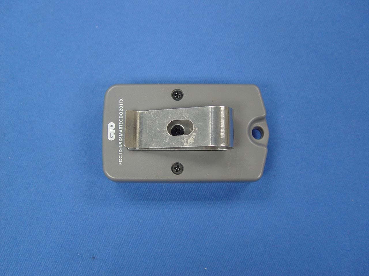
EUT (RB741, 1 button) - Front View EUT (RB741, 1 button) - Back View EUT (RB742, 2 button) - Front View EUT (RB742, 2 button) - Back View
ID Label/Location Info
FCC ID Label Sample for Model: RB741 & RB742 FCC ID: U5DRB741RB742
ID Label/Location Info
FCC ID Label This device complies with Part 15 of the FCC Rules. Operation is subject to the following two conditions: (1)this device may not cause harmful interference, and (2) this device must accept any interference received, including interference that may cause undesired operation The Label must not be a stick-on paper. The Label on these products must be permanently affixed to the product and readily visible at the time of purchase and must last the expected lifetime of the equipment not be readily detachable. Proposed Label Location on EUT EUT Bottom View/proposed FCC Mark Location FCC ID: U5DRB741RB742
Internal Photos
PCB (RB741, 1 button)-Front View PCB (RB741, 1 button)-Back View PCB (RB742, 2 button)-Front View PCB (RB742, 2 button)-Back View
Operational Description
Circuit Description of RB741 & RB742 Both RB741 (one button) and RB742 (two button) are RF transmitters for gate operator radio control system. RB741 and RB742 share the same PCB, but different assemblies. Parts (R2, D2, D5) are only installed for the second button version - RB742. Each transmitter is supplied with a 12V DC battery. The red LED on the transmitter lights on when the button is pressed, to indicate RF transmission. The red light is dim indicates that the battery in transmitter may be weak and need be replaced. HT6026 (U1) is an encoder. The HT6026 detects the setting on the 9 posts 3 throws switch (SW3) and generates code. Each post of SW3 can be set in ternary states (low, high, or open). Then, there are 3 9 = 19683 different codes for user. L2, C6, C7, Q1, and X1 are parts of the Colpitts oscillator. The oscillator generates 318MHz carrier wave. Above code signal will modulate the Colpitts oscillator. RF signal is sent out by antenna formed in PCB trace.
Schematics
X7 25FEB2008 25FEB2008 25FEB2008 183-0089 DESIGN: GTO Transmitter Schematic (2 button) 1 SHEET: OF 1 A4 1:1 00 25FEB2008 APPROVED : PILCHER SLLI X.W.LI Linear Electronics Manufactory REV: SIZE: CODE: DATED:DATED: CHECKED: DATED:DATED: RELEASED: COMPANY:TITLE: DRAWING NO: SCALE: REVISION RECORD APPROVED: ECO NO: ABD DATE: 1 2 3 4 5 6 DCAB C LTR PCB COPPER LOOP ANTENNA RB741/RB742 ( 318MHz ) Remarking : R2, D2 , D5 not installed for 1 button Q1 MMBTH10 X1 318MHz BATTERY 12VDC D2 BAS316 LED R1 4.7K SW2 R2 10K R4 620K R768R C7 10pF C6 1.8pF C4 0.1uF D5 BAS316 D4 BAS316 SW1 D3 BAS316 D1 5.1V 1 A1 2 A2 3 A3 4 A4 5 A5 6 A6/D6 7 A7/D7 8 VSS 16 VDD 15 DOUT 14 TE 13 RTC 12 CTC 11 RS 10 A9/D9 9 A8/D8 U1 HT6026 1 2 34 5 6 7 8 9 10 11 SW3 CODE SWITCH R8 100OHM R6 100OHM L2 AIR COIL 17T5 C3 100pF C5 NC C8 NC L1 1uH R5 100 C9 1uF C2 0.1uF C1 0.01uF R3 43K R9 82K
Test Report
FCC TEST REPORT Page 1 of 29 FCC ID : U5DRB741RB742 Applicant : Linear Electronics Manufactory Hourui Second Industrial Zone Hourui Village, Xixiang, Bao An County, Equipment Under Test (EUT) : Product description :GTO Transmitter Model No. : RB741 & RB742 Standards : FCC 15 Subpart C Paragraph 15.231 Date of Test : Feb.28, 2008 Test Engineer : Tiger Su Reviewed By : PERPARED BY: Waltek Services (Shenzhen) Co., Ltd. 8C,West Tower, Aidi Building, No.5003 Binhe Rd, Futian District, Shenzhen518045, Guangdong, China. Tel: 86-755-83551033 Fax: 86-755-83552400 Linear Electronics Manufactory FCC ID: U5DRB741RB742 Page 2 of 29 2 Contents Page 1 COVER PAGE..........................................................................................................................................................1 2 CONTENTS ..............................................................................................................................................................2 3 TEST SUMMARY....................................................................................................................................................4 4 GENERAL INFORMATION..................................................................................................................................5 4.1 CLIENT INFORMATION............................................................................................................................................5 4.2 GENERAL DESCRIPTION OF E.U.T...........................................................................................................................5 4.3 DETAILS OF E.U.T. .................................................................................................................................................5 4.4 DESCRIPTION OF SUPPORT UNITS...........................................................................................................................5 4.5 STANDARDS APPLICABLE FOR TESTING..................................................................................................................5 4.6 TEST FACILITY........................................................................................................................................................6 4.7 TEST LOCATION......................................................................................................................................................6 5 EQUIPMENT USED DURING TEST ...................................................................................................................7 6 CONDUCTED EMISSION TEST ..........................................................................................................................8 6.1 TEST EQUIPMENT....................................................................................................................................................8 6.2 TEST PROCEDURE...................................................................................................................................................8 6.3 CONDUCTED TEST SETUP.......................................................................................................................................9 6.4 EUT OPERATING CONDITION.................................................................................................................................9 6.5 CONDUCTED EMISSION LIMITS.............................................................................................................................10 6.6 CONDUCTED EMISSION TEST RESULT...................................................................................................................10 7 RADIATION EMISSION TEST...........................................................................................................................11 7.1 TEST EQUIPMENT..................................................................................................................................................11 7.2 MEASUREMENT UNCERTAINTY.............................................................................................................................11 7.3 TEST PROCEDURE.................................................................................................................................................11 7.4 RADIATED TEST SETUP.........................................................................................................................................12 7.5 SPECTRUM ANALYZER SETUP...............................................................................................................................12 7.6 CORRECTED AMPLITUDE & MARGIN CALCULATION............................................................................................13 7.7 SUMMARY OF TEST RESULTS................................................................................................................................13 7.8 EUT OPERATING CONDITION...............................................................................................................................14 7.9 RADIATED EMISSIONS LIMIT.................................................................................................................................14 7.10 RADIATED EMISSIONS TEST RESULT................................................................................................................15 7.10.1 Radiated Emission Test Data ................................................................................................................15 8 PERIODIC OPERATION .....................................................................................................................................17 9 BAND EDGE ..........................................................................................................................................................21 9.1 TEST PROCEDURE......................................................................................…
Text truncated - open the document above for the full version.
Test Setup Photos
Radiation Emission Test View For 30MHz-1000MHz Radiation Emission Test View For 1GHz-5GHz
Contact Information
Applicant
Nicholas Hung(General Manager)
Test Firm
Solid Industrial Co., Ltd.Yang Dengfang
Technical Specifications
| # | Rule Parts | Frequency Range | Power Output |
|---|---|---|---|
| 1 | 15.231 | 318 MHz - 318 MHz | - |
Other Applications from Linear Electronics Manufactory
U5DLINEARRB741
Apr 24, 2007Gate Opener Transmitter
Equipment Class
DSC - Part 15 Security/Remote Control Transmitter