U6VCCMGPRSCommunications Device with Bluetooth and GPRS
SHL Telemedicine Internetional Ltd.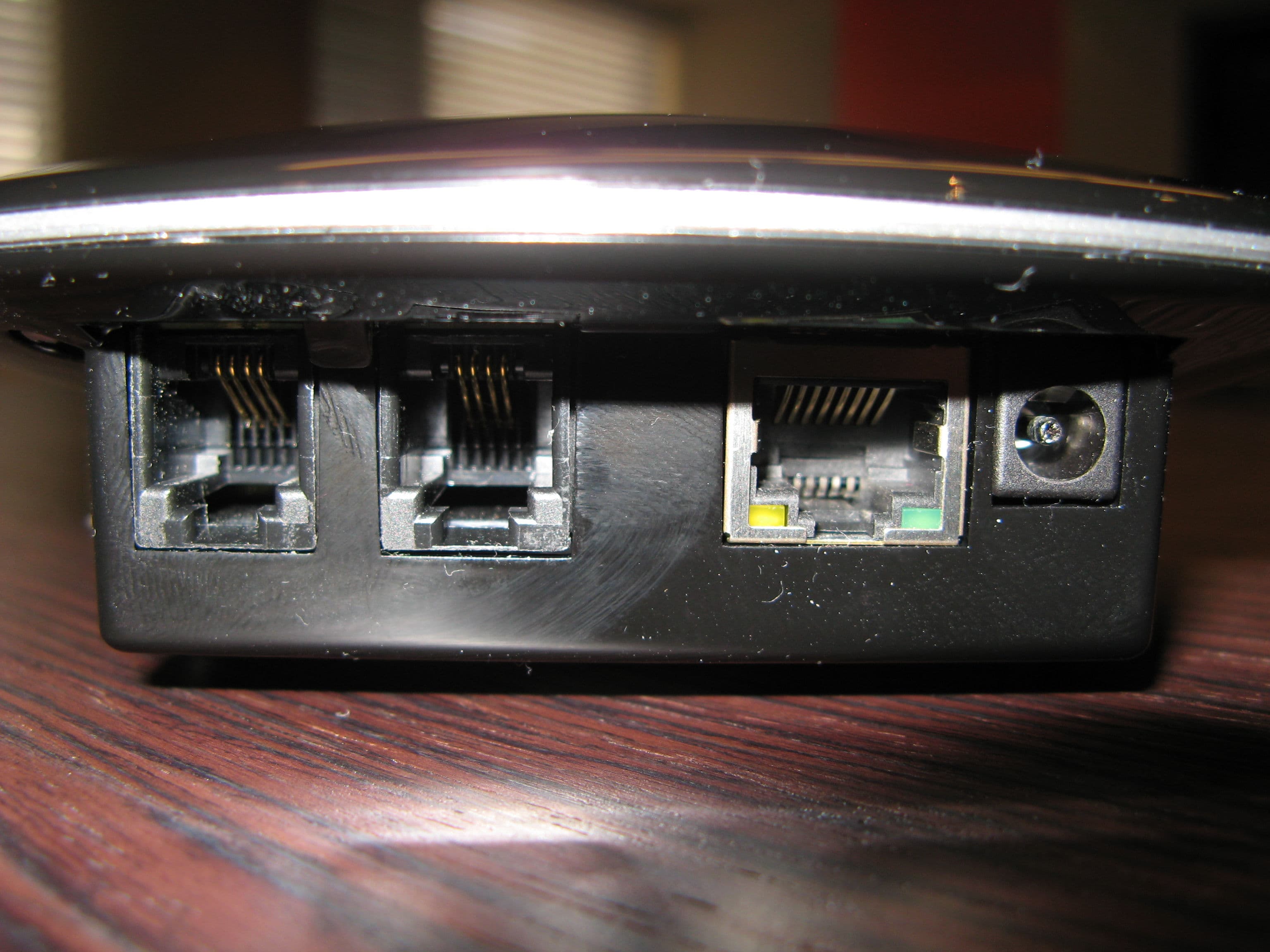
Click to zoom
Application Details
- Equipment Class
- DSS - Part 15 Spread Spectrum Transmitter
- Date of Grant
- Oct 24, 2012
- Application Purpose
- Original Equipment
- Date of Application
- Oct 24, 2012
- Equipment Note
- Communications Device with Bluetooth and GPRS
- Frequency Range
- 2402.00000000 - 2480.00000000
- Country
- Israel
Documents & Files
Document Text
Text extracted from the exhibit documents filed with the FCC. Open a document above to read the original.
Users Manual
CCM - Communication Center Module With GPRS Module User Manual October -2012 REV 2.20 CCM - Communication Center Module __________________________________________________________________________________________________ Customer service telephone number: 1-800-221818 1 Note The Quick Guide provided to you with your CCM shows the configuration for your CCM. It is strongly recommend that you read this manual carefully and in its entirety before using the CCM. The CCM can communicate with the MC in two different ways: LAN (internet) or Cellular network. The measurement devices can communicate with the CCM in three different ways: serial communication (using port 1 and port 2), USB or Bluetooth. This user manual describes all the available communication for the CCM. The quick guide provided to you with your CCM shows the communications available in your package. If you have any questions about how to use this device, do not hesitate to call our customer service for support: 1-800-221818 This telephone number appears at the bottom of each page. Warning • You can only use the CCM with devices provided by SHL. CCM - Communication Center Module __________________________________________________________________________________________________ Customer service telephone number: 1-800-221818 2 Table of Contents 1. Indications for use 3 2. Description of the CCM 4 3. Communication Options 7 4. Setting up the CCM 8 5. Taking a measurement 9 6. Handling Errors 11 7. Troubleshooting 13 8. Maintaining your CCM 14 9. Equipment classification 15 10. Operating and storage conditions 16 11. Technical specifications 17 12. Limited warranty 18 CCM - Communication Center Module __________________________________________________________________________________________________ Customer service telephone number: 1-800-221818 3 1. Indications for use The CCM device is intended to receive and transmit measurements from one or more medical devices to a remote location. The data from the medical device can be received via Bluetooth, a Serial port or a USB port. The CCM device can transmit the data to the remote location via cellular network or LAN. Warning The use of the device should always be in conjunction with a receiver capable of receiving the data. CCM - Communication Center Module __________________________________________________________________________________________________ Customer service telephone number: 1-800-221818 4 2. Description of the CCM The Communication Center Module (CCM) is a stand-alone device that receives data from measurement devices at a remote location (for example, the patient's home) and transmits the data to the Medical Center (MC). System diagram Blood pressure Weight Glucometer Etc. Bluetooth Serial Port USB LAN Cellular Modem Device To CCMToMC CCM - Communication Center Module __________________________________________________________________________________________________ Customer service telephone number: 1-800-221818 5 CCM diagram CCM Components Note: The CCM contains several LEDs (light-emitting diodes) that serve as indicator lamps. Note: All the CCM sockets are labelled on to bottom side of the CCM. 1 Power Supply (PWR). 2 Speaker 3 LAN Socket (LAN). 4 Serial Ports (Port 1, port 2). 5 USB Port (USB). 6 Multifunction Button 7 Reset button 8 SHL Heart Logo 3 4 6 9 BOTTOM VIEW TOP VIEW FRONT VIEW REAR VIEW 1 5 2 7 8 12 10 11 CCM - Communication Center Module __________________________________________________________________________________________________ Customer service telephone number: 1-800-221818 6 9 Telephone sockets (Line, Phone) – not in use. Three LEDs on top of the CCM. 10 Red indicates an error 11 Blue indicates a Bluetooth connection 12 Yellow indicates a cable connection (serial or USB), and shows if there are untransmitted measurements. Two LAN LEDs. 13 and 14 Green and Yellow indicates a LAN connection 15 Red LED on the rear side indicates a cellular communication 13 14 15 CCM - Communication Center Module __________________________________________________________________________________________________ Customer service telephone number: 1-800-221818 7 3. Communication Options Caution The User Manual describes all the ways a measurement device can communicate with the CCM. The User Manual also describes all the ways the CCM can communicate with the MC. Please refer to the communication options available at your CCM as defined in the quick guide. How does the CCM communicate with the MC? The CCM can communicate with the MC in one of two different ways: LAN Interface: Connects the CCM to the MC using your local area network (LAN) - (see component 3 on the CCM diagram above). This way is the fastest way to send the data to the MC. Cellular Modem : Connects the CCM to the MC using a cellular modem. How does a measurement device communicate with the CCM? A measurement device can communicate with the CCM in one of three different ways: Serial Port: This is a cable connection to the CCM. The CCM can communicate with two 2 devices at the same time (see component 4 on the CCM diagram above). Bluetooth Wireless: This is wireless communication to the CCM. It can communicate with up to 7 devices at the same time. USB: This is also a cable connection to the CCM. It connects to a USB port on your CCM (see component 5 on the CCM diagram above). CCM - Communication Center Module __________________________________________________________________________________________________ Customer service telephone number: 1-800-221818 8 4. Setting up the CCM Step 1: Power up the CCM Connect the power cord plug into an electrical outlet (Figure 1) and the transformer cable (Figure 2) into the back side of the CCM (Figure 3). All the LED's on the CCM light up and stay lit for 2 seconds. The orange SHL heart logo stays lit as long as the CCM is connected. Step 2: CCM to MC Communication LAN Interface: This is a LAN connection to the MC. Connect one end of the LAN cable into the …
Text truncated - open the document above for the full version.
Block Diagram
CCM GPRS Architecture Block Diagram Architecture Block Diagram - GPRS The following shows the CCM architectural block diagram: RTC + Backup Capacitor Speaker LEDs RS232 Ports Basic Communication Card GPRS Balcony card PIC32 μC + ICP BT Module Class 1 2400MHz Flash USB UART I 2 C I/O COM Port Cellular Modem GSM/DCS/PCS LAN Power Supply UART SPI
Cover Letter(s)
RFI Global Services Ltd Pavilion A, Ashwood Park, Ashwood Way, Basingstoke, Hampshire, RG23 8BG Tel: +44 (0) 1256 312000 Fax: +44 (0) 1256 312001 Email: [email protected] Website: www.rfi-global.com Registered in England and Wales Company number: 2117901 FCC ID: U6VCCMGPRS This is to confirm the applicability of Part 15C Test Report EF/2006/20016 (01 April 2006), Test Report RFI-RPT-RP77787JD08A (08 November 2010), and Part 22/ 24 Test Report RFI-RPT-RP76937JD03B (20 Sept. 2010) for application FCC ID: U6VCCMGPRS. These reports cover the conducted EMC measurements of the previously certified Bluetooth module (FCC ID: QOQWT11) and GPRS module (FCC ID: RI7GE865), which are integrated, unmodified, in the CCM equipment. RFI Global Services Ltd
Operational Description
CCM - Communication Center Module Operational Description - GPRS 1.0 Release Date: 27/10/2012 Mariano Lasebnik Page 1 of 4 Confidential. The copyright of this document is the property of SHL Telemedicine Ltd. This document is issued on the condition that it is not reproduced, nor its contents disclosed to any third party without the prior written consent of SHL Telemedicine. CCM Project Communication Center Module Operational Description GPRS CCM - Communication Center Module Operational Description - GPRS 1.0 Release Date: 27/10/2012 Mariano Lasebnik Page 2 of 4 Confidential. The copyright of this document is the property of SHL Telemedicine Ltd. This document is issued on the condition that it is not reproduced, nor its contents disclosed to any third party without the prior written consent of SHL Telemedicine. Overview The CCM GPRS includes 2 integrated RF-modules. GSM and BT modules: Telit GE865-QUAD GSM/DCS/PCS module Bluegiga WT11-A BT version 2.0 + EDR, Class 1 CCM Operational Description The Communication Center Module (CCM) device inputs data from medical measurement devices that are attached to it (for example, at a patient's home). The CCM then transmits this data to a remote Medical Center (MC) for analysis and diagnosis. The CCM can receive instructions from the MC, which can be played for the patient. The use of the device is always in conjunction with a medical center capable of receiving and handling the data. CCM Communication Options CCM ↔ MC The CCM can communicate with the MC via LAN as its default. In addition, a CCM have a Cellular balcony card installed inside it. • LAN Interface: Uses the Internet or Local Area Network (LAN) connected to it. The CCM uses this communication method as the default option, even when a balcony card is installed. • Cellular Modem (GPRS): Uses the cellular modem balcony card in the CCM. CCM ↔ Measurement Devices Measurement devices can communicate with the CCM using one of the following methods: • Bluetooth Wireless: The CCM can communicate with up to seven measurement devices simultaneously via Bluetooth wireless communication. • Serial Port: The CCM can communicate with up to two measurement devices simultaneously via the two RJ-45 connectors at the rear of the CCM. • USB: The CCM can communicate with a measurement device via the mini- USB port on the CCM. CCM - Communication Center Module Operational Description - GPRS 1.0 Release Date: 27/10/2012 Mariano Lasebnik Page 3 of 4 Confidential. The copyright of this document is the property of SHL Telemedicine Ltd. This document is issued on the condition that it is not reproduced, nor its contents disclosed to any third party without the prior written consent of SHL Telemedicine. Cellular Communication to MC The communication to the MC is handled via a Cellular connection when no LAN (Internet) communication is available and a cellular balcony card is installed in the CCM. After power on the CCM the cellular communication is initiated. The transmission is intermittent, that is, very short data transmission (less than 100 KB) several times per day (maximum). GSM Operation The CCM GPRS device contains a Telit GE865-QUAD GSM modem operating in the United States on GSM 850 / PCS 1900 MHz to communicate user medical data to the central medical centre. The modem is used to establish a GPRS data session over the cellular network (voice communications is not supported). The GE865-QUAD module used has GPRS Class 10 functionality and has a nominal peak output power of 2 watts (+33dBm) at GSM 850 and 1 watt (+30dBm) at PCS 1900) respectively. GSM burst frequency is 216Hz = 4,63ms There are 8 timeslots so 4,63 / 8 = 578us GPRS class10 is 2 TX timeslot, 2 of 8 slots = 25% Therefore the duty cycle is 25% Antenna The antenna is designed as a PCB printed antenna. The GE865-QUAD uses a PCB printed antenna antenna, which has a maximum gain of 2.30dBi at 850 MHz and 3.01dBi at 1900 MHz. The modulation type used is GMSK. CCM - Communication Center Module Operational Description - GPRS 1.0 Release Date: 27/10/2012 Mariano Lasebnik Page 4 of 4 Confidential. The copyright of this document is the property of SHL Telemedicine Ltd. This document is issued on the condition that it is not reproduced, nor its contents disclosed to any third party without the prior written consent of SHL Telemedicine. Handling BT Devices The CCM is defined to interact with different devices via Bluetooth. Bluetooth Operation The CCM GPRS device contains a Bluegiga WT11-A module operating in the 2402 to 2480 MHz ISM frequency band. The maximum output power is 63 mW (+18dBm) This device is a Frequency Hopping device with 79 hopping frequencies Modulation types used are GFSK, pi/4-DQPSK and 8DPSK. Data rates up to 1 Mbps are supported with GFSK modulation. Data rates up to 2 Mbps are supported with pi/4-DQPSK modulation. Data rates up to 3 Mbps are supported with 8DPSK modulation. Bluetooth Antenna The antenna is an integrated chip antenna and is build in the Bluegiga WT11-A module. The antenna is ACX AT3216, Chip Antenna, 0.5dBi.
Test Report
REPORT NO: EF/2006/20016 ID: QOQWT11 DATE: Apr. 01, 2006 Page: 1 of 60 The results shown in this test report refer only to the sample(s) tested unless otherwise stated. This test report cannot be reproduced, except in full, without prior written permission of the Company. SGS Taiwan Ltd. No. 134, Wu Kung Rd., Wuku Industrial Zone, Taipei Country, Taiwan. / 台北縣五股工業區五工路134號 台灣檢驗科技股份有限公司 t (886-2) 2299-3939 f (886-2) 2298-2698 www.sgs.com.tw ELECTROMAGNETIC EMISSIONS COMPLIANCE REPORT INTENTIONAL RADIATOR CERTIFICATION TO FCC PART 15 SUBPART C REQUIREMENT FULL MODULE APPROVE OF Product Name: Bluetooth Class I EDR Module Brand Name: Bluegiga Model Name: WT11# Model Differences: N/A FCC ID: QOQWT11 Report No.: EF/2006/20016 Issue Date: Apr. 01, 2006 FCC Rule Part: §15.247 Prepared for: Bluegiga Technologies Sinikalliontie 11, 02630 ESPOO, FINLAND Prepared by: SGS Taiwan Ltd. No. 134, Wu Kung Rd., Wuku Industrial Zone, Taipei County, Taiwan. Note: This report shall not be reproduced except in full, without the written approval of SGS Taiwan Ltd. This document may be altered or revised by SGS Taiwan Ltd. personnel only, and shall be noted in the revision section of the document. REPORT NO: EF/2006/20016 ID: QOQWT11 DATE: Apr. 01, 2006 Page: 2 The results shown in this test report refer only to the sample(s) tested unless otherwise stated. This test report cannot be reproduced, except in full, without prior written permission of the Company. SGS Taiwan Ltd. No. 134, Wu Kung Rd., Wuku Industrial Zone, Taipei Country, Taiwan. / 台北縣五股工業區五工路134號 台灣檢驗科技股份有限公司 t (886-2) 2299-3939 f (886-2) 2298-2698 www.sgs.com.tw VERIFICATION OF COMPLIANCE Applicant: Bluegiga Technologies Sinikalliontie 11, 02630 ESPOO, FINLAND Equipment Under Test: Bluetooth Class I EDR Module Brand Name: Bluegiga FCC ID Number: QOQWT11 Model No.: WT11# Model Difference: N/A File Number: EF/2006/20016 Date of test: Mar. 12, 2006 ~ Mar. 31, 2006 Date of EUT Received: Mar. 12, 2006 We hereby certify that: The above equipment was tested by SGS Taiwan Ltd. The test data, data evaluation, test proce- dures, and equipment configurations shown in this report were made in accordance with the procedures given in ANSI C63.4 (2003) and the energy emitted by the sample EUT tested as described in this report is in compliance with conducted and radiated emission limits of FCC Rules Part 15.247. The test results of this report relate only to the tested sample identified in this report. Test By: Date Apr. 01, 2006 Alex Hsieh Prepared By: Date Apr. 01, 2006 Elisa Chen Approved By: Date Apr. 01, 2006 Vincent Su REPORT NO: EF/2006/20016 ID: QOQWT11 DATE: Apr. 01, 2006 Page: 3 The results shown in this test report refer only to the sample(s) tested unless otherwise stated. This test report cannot be reproduced, except in full, without prior written permission of the Company. SGS Taiwan Ltd. No. 134, Wu Kung Rd., Wuku Industrial Zone, Taipei Country, Taiwan. / 台北縣五股工業區五工路134號 台灣檢驗科技股份有限公司 t (886-2) 2299-3939 f (886-2) 2298-2698 www.sgs.com.tw Version Version No. Date 00 Apr. 01, 2006 REPORT NO: EF/2006/20016 ID: QOQWT11 DATE: Apr. 01, 2006 Page: 4 The results shown in this test report refer only to the sample(s) tested unless otherwise stated. This test report cannot be reproduced, except in full, without prior written permission of the Company. SGS Taiwan Ltd. No. 134, Wu Kung Rd., Wuku Industrial Zone, Taipei Country, Taiwan. / 台北縣五股工業區五工路134號 台灣檢驗科技股份有限公司 t (886-2) 2299-3939 f (886-2) 2298-2698 www.sgs.com.tw Table of Contents 1. GENERAL INFORMATION .........................................................................................................7 1.1. Product Description ............................................................................................................................7 1.2. Related Submittal(s) / Grant (s) ..........................................................................................................7 1.3. Test Methodology ...............................................................................................................................7 1.4. Test Facility.........................................................................................................................................7 1.5. Special Accessories .............................................................................................................................7 1.6. Equipment Modifications....................................................................................................................7 2. SYSTEM TEST CONFIGURATION ............................................................................................8 2.1. EUT Configuration .............................................................................................................................8 2.2. EUT Exercise ......................................................................................................................................8 2.3. Test Procedure.....................................................................................................................................8 2.4. Configuration of Tested System..........................................................................................................9 3. SUMMARY OF TEST RESULTS ...............................................................................................10 4. DESCRIPTION OF TEST MODES ............................................................................................10 5. CONDUCTED EMISSION TEST................................................................................................11 5.1. Standard Applicable ..........................................................................................................................11 5.2. EUT Setup.........................................................................................................................................11 5.3. Measurement Procedure..........…
Text truncated - open the document above for the full version.
Test Report
TEST REPORT FROM RFI GLOBAL SERVICES LTD Test of: CCM FCC ID: U6VCCM To: FCC Part 15.247(d) & 15.207 Test Report Serial No: RFI-RPT-RP77787JD08A This Test Report Is Issued Under The Authority Of Chris Guy, Head of Global Approvals: Checked By: A. Henriques Signature: Date of Issue: 08 November 2010 The Bluetooth ® word mark and logos are owned by the Bluetooth SIG, Inc. and any use of such marks by RFI Global Services Ltd. is under license. Other trademarks and trade names are those of their respective owners. This report is issued in Adobe Acrobat portable document format (PDF). It is only a valid copy of the report if it is being viewed in PDF format with the following security options not allowed: Changing the document, Selecting text and graphics, Adding or changing notes and form fields. This report may not be reproduced other than in full, except with the prior written approval of RFI Global Services Ltd. The results in this report apply only to the sample(s) tested. TEST REPORT SERIAL NO: RFI-RPT-RP77787JD08A VERSION NO. 1.0 ISSUE DATE: 08 NOVEMBER 2010 Page 2 of 19 RFI Global Services Ltd This page has been left intentionally blank. TEST REPORT SERIAL NO: RFI-RPT-RP77787JD08A VERSION NO. 1.0 ISSUE DATE: 08 NOVEMBER 2010 RFI Global Services Ltd Page 3 of 19 Table of Contents 1. Customer Information .................................................................................................................. 4 2. Summary of Testing ..................................................................................................................... 5 2.1. General Information 5 2.2. Summary of Test Results 5 2.3. Methods and Procedures 5 2.4. Deviations from the Test Specification 5 3. Equipment Under Test (EUT) ....................................................................................................... 6 3.1. Identification of Equipment Under Test (EUT) 6 3.2. Description of EUT 6 3.3. Modifications Incorporated in the EUT 6 3.4. Additional Information Related to Testing 7 3.5. Support Equipment 7 4. Operation and Monitoring of the EUT during Testing ............................................................... 8 4.1. Operating Modes 8 4.2. Configuration and Peripherals 8 5. Measurements, Examinations and Derived Results .................................................................. 9 5.1. General Comments 9 5.2. Test Results 10 5.2.1. Transmitter AC Conducted Spurious Emissions 10 5.2.2. Transmitter Radiated Emissions 12 6. Measurement Uncertainty .......................................................................................................... 18 Appendix 1. Test Equipment Used ................................................................................................ 19 TEST REPORT SERIAL NO: RFI-RPT-RP77787JD08A VERSION NO. 1.0 ISSUE DATE: 08 NOVEMBER 2010 Page 4 of 19 RFI Global Services Ltd 1. Customer Information Company Name: SHL Telemedicine International Ltd Address: 90 Yigal Alon Tel Aviv 67891 Israel TEST REPORT SERIAL NO: RFI-RPT-RP77787JD08A VERSION NO. 1.0 ISSUE DATE: 08 NOVEMBER 2010 RFI Global Services Ltd Page 5 of 19 2. Summary of Testing 2.1. General Information Specification Reference: 47CFR15.247(d) Specification Title: Code of Federal Regulations Volume 47 (Telecommunications) 2010: Part 15 Subpart C (Intentional Radiators) - Section 15.247(d) Specification Reference: 47CFR15.207 and 47CFR15.209 Specification Title: Code of Federal Regulations Volume 47 (Telecommunications) 2010: Part 15 Subpart C (Intentional Radiators) - Sections 15.207 and 15.209 Site Registration: FCC: 209735 Location of Testing: RFI Global Services Ltd, Wade Road, Basingstoke, Hampshire, RG24 8AH. Test Dates: 6 October to 26 October 2010 2.2. Summary of Test Results FCC Reference (47CFR) Measurement Result Part 15.207 Transmitter AC Conducted Emissions Part 15.247(d) & 15.209(a) Transmitter Radiated Emissions Key to Results = Complied = Did not comply 2.3. Methods and Procedures Reference: ANSI C63.4 (2009) Title: American National Standard for Methods of Measurement of Radio-Noise Emissions from Low-Voltage Electrical and Electronic Equipment in the Range of 9 kHz to 40 GHz Reference: ANSI C63.10 (2009) Title: American National Standard for Testing Unlicensed Wireless Devices 2.4. Deviations from the Test Specification For the measurements contained within this test report, there were no deviations from, additions to, or exclusions from the test specification identified above. TEST REPORT SERIAL NO: RFI-RPT-RP77787JD08A VERSION NO. 1.0 ISSUE DATE: 08 NOVEMBER 2010 Page 6 of 19 RFI Global Services Ltd 3. Equipment Under Test (EUT) 3.1. Identification of Equipment Under Test (EUT) Brand Name: SHL Telemedicine Model Name or Number: CCM Serial Number(s): 1001019; 1001011 IMEI Number: 357460032903218; 357460032901717 Hardware Version Number: 2.0 Software Version Number: 2.0 FCC ID: U6VCCM Description: AC/DC adapter Brand Name: EDACPOWER Electronics Model Name or Number: EA1020CR 3.2. Description of EUT The equipment under test was a communication system for medical devices. The EUT has an integral antenna and is powered from a 120 VAC 60 Hz AC adapter supplying a 15 Volt DC output. 3.3. Modifications Incorporated in the EUT No modifications were applied to the EUT during testing. TEST REPORT SERIAL NO: RFI-RPT-RP77787JD08A VERSION NO. 1.0 ISSUE DATE: 08 NOVEMBER 2010 RFI Global Services Ltd Page 7 of 19 3.4. Additional Information Related to Testing Tested Technology: Bluetooth Power Supply Requirement: Nominal 15 VDC via AC adapter Type of Unit: Transceiver Channel Spacing: 1 MHz Mode: Basic Rate Enhanced Data Rate Modulation: GFSK π/4-DQPSK 8DQPSK Packet Type: (Maximum Payload) DH5 2DH5 3DH5 Data Rate (Mbit/s): 1 2 3 Transmit Frequency Range: 2402 MHz to 2480 MHz Transmit Channels Tested: Channel ID Channel Number Channel Frequency (MHz) Bottom 0 2402 Middle 39 2441 Top 78 2480 3.5. Support Equipment The following support equipment was used to exercise the …
Text truncated - open the document above for the full version.
Contact Information
Applicant
Roni Kazaz
Technical Contact
SHL Telemedicine International Ltd.Roni Kazaz
[email protected]+972-3-5612212
90 Yigal Alon st. · Tel Aviv · Israel
Non-Technical Contact
SHL Telemedicine International Ltd.Iki Alroy
[email protected]+972-3-5612212
Test Firm
UL VS LtdDarren Rust
Technical Specifications
| # | Rule Parts | Frequency Range | Power Output |
|---|---|---|---|
| 1 | 15C | 2.40 GHz - 2.48 GHz | 23.00 mW |
Other Applications from SHL Telemedicine Internetional Ltd.

U6VCBSENC
Sep 06, 2007Cardio Sen`C
Equipment Class
PCB - PCS Licensed Transmitter