U7ORFID1RFID Option
ITW Food Equipment Group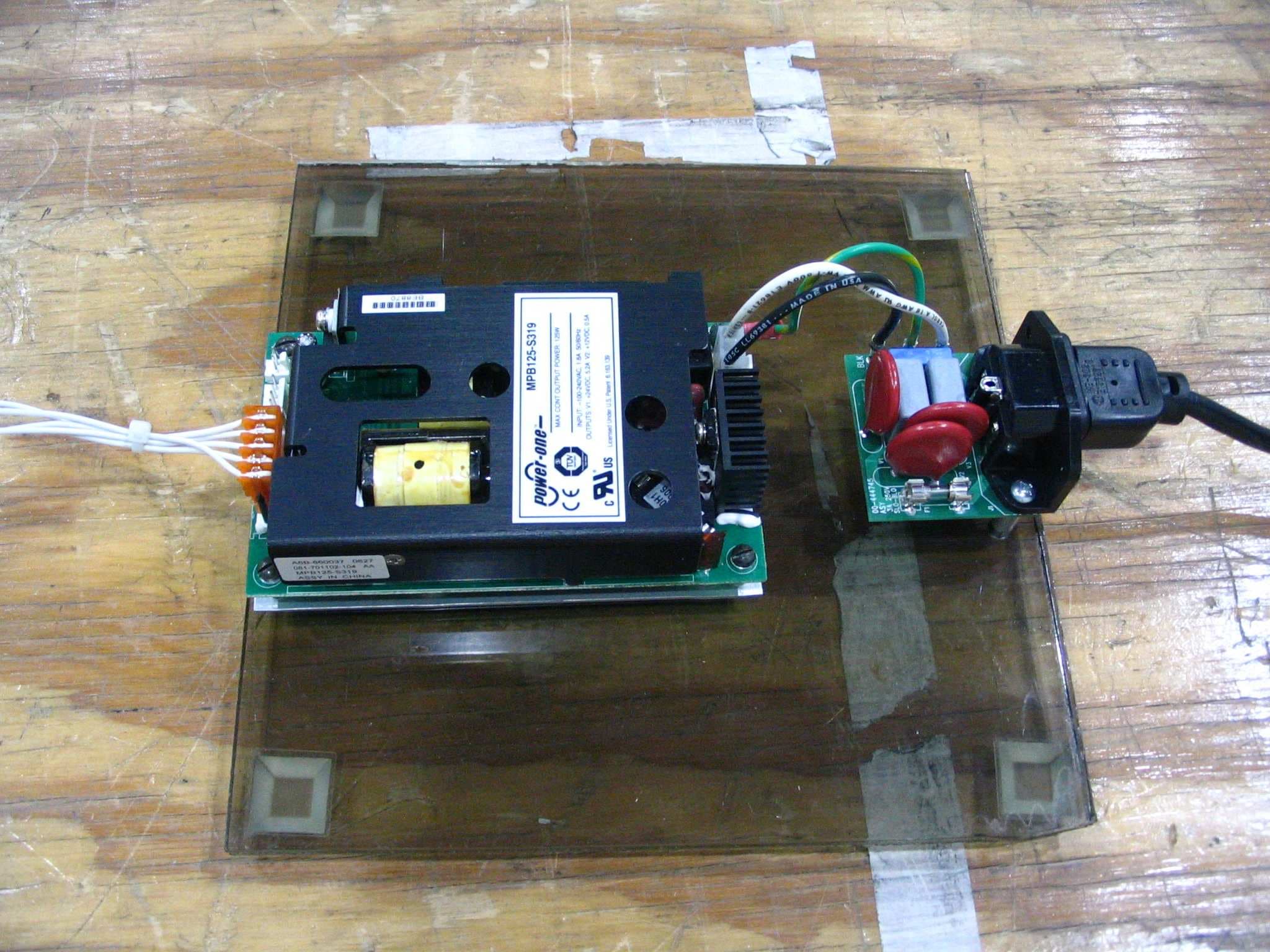
Click to zoom
Application Details
- Equipment Class
- DCD - Part 15 Low Power Transmitter Below 1705 kHz
- Date of Grant
- Oct 02, 2007
- Application Purpose
- Original Equipment
- Date of Application
- Oct 02, 2007
- Equipment Note
- RFID Option
- Frequency Range
- 0.13420000 - 0.13420000
- Company
- ITW Food Equipment Group
- Country
- United States
Documents & Files
Document Text
Text extracted from the exhibit documents filed with the FCC. Open a document above to read the original.
Users Manual
F-35516 (May 2007) HLX Scale System Operator Manual ML-29278HLX Scale 701 S. RIDGE AVENUE TROY, OHIO 45374 www.hobartcorp.com Review Copy 6/1/07 Review Copy 6/1/07 HLX Scale System Operator Manual F-35516 (May 2007)iTable of Contents TABLE OF CONTENTS Chapter 1: Introduction. . . . . . . . . . . . . . . . . . . . . . . . . . . . . . . . . . . . . . . . . . . . . . . . . . . . . . . . . . . . . . .1-1 Welcome . . . . . . . . . . . . . . . . . . . . . . . . . . . . . . . . . . . . . . . . . . . . . . . . . . . . . . . . . . . . . .1-1 FCC Note . . . . . . . . . . . . . . . . . . . . . . . . . . . . . . . . . . . . . . . . . . . . . . . . . . . . . . . . . . . . .1-1 Verify Correctness of Weight and Price . . . . . . . . . . . . . . . . . . . . . . . . . . . . . . . . . . . . . .1-2 Operator Manual Terminology . . . . . . . . . . . . . . . . . . . . . . . . . . . . . . . . . . . . . . . . . . . . .1-2 Important Information . . . . . . . . . . . . . . . . . . . . . . . . . . . . . . . . . . . . . . . . . . . . . . . . . . .1-2 Chapter 2: Understanding the System . . . . . . . . . . . . . . . . . . . . . . . . . . . . . . . . . . . . . . . . . . . . . . . . . . .2-1 Electrical Connections . . . . . . . . . . . . . . . . . . . . . . . . . . . . . . . . . . . . . . . . . . . . . . . . . . .2-1 Communication Connections . . . . . . . . . . . . . . . . . . . . . . . . . . . . . . . . . . . . . . . . . . . . . .2-1 Operator Start Screen . . . . . . . . . . . . . . . . . . . . . . . . . . . . . . . . . . . . . . . . . . . . . . . . . . . .2-2 Chapter 3: Using the HLX Scale System . . . . . . . . . . . . . . . . . . . . . . . . . . . . . . . . . . . . . . . . . . . . . . . . .3-1 Power Up the System . . . . . . . . . . . . . . . . . . . . . . . . . . . . . . . . . . . . . . . . . . . . . . . . . . . .3-1 Logging onto the System . . . . . . . . . . . . . . . . . . . . . . . . . . . . . . . . . . . . . . . . . . . . . . . . .3-1 Using RFID Option . . . . . . . . . . . . . . . . . . . . . . . . . . . . . . . . . . . . . . . . . . . . . . . . . . . . .3-2 Shutting Down the System . . . . . . . . . . . . . . . . . . . . . . . . . . . . . . . . . . . . . . . . . . . . . . . .3-3 Power Button . . . . . . . . . . . . . . . . . . . . . . . . . . . . . . . . . . . . . . . . . . . . . . . . . . . . . . . . . .3-4 Operator Start Screen Menu Buttons and Flashkeys . . . . . . . . . . . . . . . . . . . . . . . . . . . .3-4 Run Screen . . . . . . . . . . . . . . . . . . . . . . . . . . . . . . . . . . . . . . . . . . . . . . . . . . . . . . . . . . . .3-5 Modifying the Run Screen . . . . . . . . . . . . . . . . . . . . . . . . . . . . . . . . . . . . . . . . . . . . . . . .3-6 Running a Product . . . . . . . . . . . . . . . . . . . . . . . . . . . . . . . . . . . . . . . . . . . . . . . . . . . . . .3-7 Using the Operator Run Screen Drop-Down Menus . . . . . . . . . . . . . . . . . . . . . . . . . . . .3-8 Product Drop-Down Menu . . . . . . . . . . . . . . . . . . . . . . . . . . . . . . . . . . . . . . . . . . . . . . . .3-9 Settings Drop-Down Menu. . . . . . . . . . . . . . . . . . . . . . . . . . . . . . . . . . . . . . . . . . . . . . .3-15 Help Drop-Down Menu . . . . . . . . . . . . . . . . . . . . . . . . . . . . . . . . . . . . . . . . . . . . . . . . .3-18 Chapter 4: Maintenance & Cleaning . . . . . . . . . . . . . . . . . . . . . . . . . . . . . . . . . . . . . . . . . . . . . . . . . . . .4-1 Removing the Label Cassette . . . . . . . . . . . . . . . . . . . . . . . . . . . . . . . . . . . . . . . . . . . . .4-1 Installing the Label Cassette . . . . . . . . . . . . . . . . . . . . . . . . . . . . . . . . . . . . . . . . . . . . . . .4-1 Removing the Label Roll . . . . . . . . . . . . . . . . . . . . . . . . . . . . . . . . . . . . . . . . . . . . . . . . .4-2 Loading the Label Cassette. . . . . . . . . . . . . . . . . . . . . . . . . . . . . . . . . . . . . . . . . . . . . . . .4-2 Removing the Scale Platter. . . . . . . . . . . . . . . . . . . . . . . . . . . . . . . . . . . . . . . . . . . . . . . .4-3 Installing the Scale Platter . . . . . . . . . . . . . . . . . . . . . . . . . . . . . . . . . . . . . . . . . . . . . . . .4-3 Adjusting Console Position . . . . . . . . . . . . . . . . . . . . . . . . . . . . . . . . . . . . . . . . . . . . . . .4-3 Adjusting the Scale Feet . . . . . . . . . . . . . . . . . . . . . . . . . . . . . . . . . . . . . . . . . . . . . . . . . .4-4 Cleaning the Printhead . . . . . . . . . . . . . . . . . . . . . . . . . . . . . . . . . . . . . . . . . . . . . . . . . . .4-5 Cleaning the Exterior of Scale . . . . . . . . . . . . . . . . . . . . . . . . . . . . . . . . . . . . . . . . . . . . .4-6 Troubleshooting . . . . . . . . . . . . . . . . . . . . . . . . . . . . . . . . . . . . . . . . . . . . . . . . . . . . . . . .4-6 Index: . . . . . . . . . . . . . . . . . . . . . . . . . . . . . . . . . . . . . . . . . . . . . . . . . . . . . . . . . . . . . . . . . . . . . . . . . . . . I-1 Review Copy 6/1/07 HLX Scale System Operator Manual Table of ContentsiiF-35516 (May 2007) Java is a trademark of Sun Microsystems, Inc. Copyright © 2007 General Software Inc. All Rights Reserved © Hobart, A division of ITW Food Equipment Group LLC 2007 Review Copy 6/1/07 HLX Scale System Operator Manual F-35516 (May 2007)1-1Introduction Chapter 1: Introduction Introduction WelcomeThe HLX Scale System is perfect for your over-the-counter weighing applications. This weighing system can handle a broad variety of products for deli, produce, seafood, and cheese depart- ments. It enhances your merchandising capabilities with multiple fonts, graphics, and label types. HLX Scale System All necessary operator data appears on the touch screen. FCC Note This equipment has been tested and found to comply with the limits for a Class A digital device, pursuant to Part 15 of the FCC rules. These limits are designed to provide reasonable protection against harmful interference when the equipment is operated in a c…
Text truncated - open the document above for the full version.
Users Manual
©HOBART 2007 F25238 (April 2007)Page 1 of 4 INSTALLATION INSTRUCTIONS RFID UPGRADE KIT PART NO. 445130 RFID UPGRADE KIT CONTENTS ID #Part #QTY. Description . . .. . . 1Instructions 14450991Cable assembly, RFID antenna 24448471Cable assembly, RFID 34450291Board assembly, RFID 4SD-037-712Screw, drive #6 54451281Label, RFID FCC Reference Picture Required Reference Material HLX Service Counter Scale Service Manual. Installation Procedure 1.Make a backup of the HLX data base. 2.If scale is powered, touch System > Shutdown and follow prompts to shut down. WARNING: DISCONNECT THE ELECTRICAL POWER TO THE MACHINE AND FOLLOW LOCKOUT / TAGOUT PROCEDURES. 3.Remove MAIN HOUSING. 4.Disconnect cable from J22 on main board. NOTE: On J22 the retainer that secures the ribbon cable must be pulled up to release pressure on the cable before pulling cable out of connector. When installing, fully seat cable, then press retainer down to secure cable. 5.Release console assembly from base by pushing in and holding console latch buttons, pivoting the assembly to its highest upward position and lifting console assembly upward. A.Lay on a padded surface to protect touch screen. 6.Remove six screws securing back housing and lift housing off. F25238 (April 2007) ©HOBART 2007Page 2 of 4 7.Disconnect J1 from console adapter board. NOTE: On J1 the retainer that secures the ribbon cable must be pulled up to release pressure on the cable before pulling cable out of connector. When installing, fully seat cable, then press retainer down to secure cable. 8.Remove four screws securing display mounting plate with display and lift out display assembly. 9.Mount RFID board using two screws from kit to secure board to console housing. 10. Connect antenna cable plug to RFID board J2. Tuck wires behind post as shown and route cable down to corner of housing. 11. Tuck cable with stripped insulation part behind post as shown. 12. Working clockwise, tuck in the other areas as shown. 13. Tuck other part of cable with stripped insulation behind post as shown. 14. Working clockwise, continue to tuck antenna into areas shown. Be sure touch screen ribbon cable is in front of antenna cable. ©HOBART 2007 F25238 (April 2007)Page 3 of 4 15. Connect antenna cable plug to J1 on RFID board. Dress wires as shown. 16. Make sure hands are clean. Use a cleaner such as Windex® Glass Cleaner. Spray cleaner on lint free cloth and clean all dirt and lint from inside touch screen surface and front of display before reassembly. 17. Reinstall display assembly. 18. Connect end of cable from kit to J4 on console adapter board. 19. Connect cable from console adapter board to RFID board J3 20. Three jumpers must be installed on RFID board. Each jumper is connecting two pins at each location 1, 2, and 4. Numbers 1, 2, and 4 must be visible. 21. Reassemble in reverse order. 22. Apply power to scale. 23. When scale displays the operate screen, insert USB service key. 24. Touch System > Service Mode > Peripherals > RFID. NOTE: If RFID does not show in the peripherals menu, check that cable connections between console adapter board and RFID board are good. 25. Screen similar to below should display. F25238 (April 2007) ©HOBART 2007Page 4 of 4 26. RFID tag can be a wristband or other device. Wristband shown. 27. When tag is within 9" of the center of the display, the display should change to display tag identification number. Face of tag must be parallel with display. 28. When tag is moved out of range, and after a delay, numbers change to all zeros indicating tag is not being sensed. NOTE: If display does not show tag ID number, check that antenna is properly connected to RFID board. If still not operating, check with known good tag. If still not operating, replace antenna and/or RFID board. 29. Affix RFID FCC label onto scale next to data plate. This label is required to be in place on any scale using RFID. 30. Check for proper operation.
Block Diagram
134.2 kHz
Cover Letter(s)
World Headquarters 701 Ridge Avenue Troy, Ohio 45374 937 332-3000 EQUIPMENT. SYSTEMS AND SERVICES FOR THE WORLD’S FOOD INDUSTRY... IN OVER 100 COUNTRIES 1 of 1 Letter of Agency I appoint Intertek Testing Services NA Inc. to act on our behalf in front of the Federal Communications Commission with respect to all matters relating to certification of equipment under the FCC rules until further notice. I further certify that no party (as defined in 1.2002 of CFR 47, 1995) to this application, including myself, is subject to denial of federal benefits, that includes FCC benefits, pursuant to Section 5301 of the Anti-Drug Abuse Act of 1988, 21 U.S.C.,853A. Equipment: _________________RFID-1__(FCC ID U70RFID1)_____________________ Dated this _3rd __day of__August_______, 2007_. Signature __James Meyer ________________________ Name __Manager, Product Support Engineering ___ Title __ITW Food Equipment Group ___________ Company __937-332-2432_______________________ Telephone
External Photos
RFID Module and Antenna Power Supply HLXP Scale
ID Label/Location Info
Label location
Operational Description
Functional Description RFID-1 installed in HLX Scale/Printer RFID-1 description The RFID upgrade kit (p.n. 445130) is factory or field installed into model HLX scale/printers by Hobart factory trained service technicians, per installation instructions in the Appendix. The transmitter portion of the RFID reader operates at 134.2 KHz and is subject to FCC part 15, subpart C, “Intentional Radiator”, paragraphs 15.207 and 15.209. The digital electronics portion of the RFID reader and the HLX scale/printer to which it installed is subject to FCC part 15, subpart B, “Unintentional Radiator”, paragraph 15.109 under the Class A limits. RFID transponder read operation The transponder is a battery-less device that is powered from the magnetic field generated by the RFID reader and antenna. The transponder can be in the form of a wristband, key fob or access card, among others. The reader drives the resonant antenna for 50 msec at 134.2 KHz to charge a nearby transponder. After the charge cycle, the antenna is no longer driven and is switched to a receive mode. The transponder sends its unique 64 bit code within 20 msec to the reader by frequency modulation (logic 1 is ~122 KHz & logic 0 is ~134 KHz). The antenna, also resonant in receive mode, amplifies the weak transponder signal. Several stages of amplification & band pass filtering precede the frequency demodulation. RFID system details The two main components of the RFID reader are the RFID reader board assembly (p.n. 445029) and RFID antenna (p.n. 445099) which are installed in the operator console by the service technician per installation instructions, F-25238 (see the Appendix). The RFID reader board assembly contains a TI low frequency RFID reader module (TI p.n. RI-STU-MRD1). RFID reader board description The RFID reader board assembly is powered by +24VDC supplied from the HLX power supply routed through the main board assembly and console board assembly. The +24VDC is converted to +8.3 VDC by a buck switching regulator, then post regulated by a +5VDC linear regulator which supplies both the RFID logic and antenna drive circuits. Communication between the RFID reader micro controller and the host processor on the main board is by UART at 5VDC logic levels. Higher quality resonating circuit capacitors and receiver band pass filter circuit replace similar functions on the TI RFID module for better receive performance. Although there are 3 jumpers on the RFID reader board to allow resonant tuning of the antenna, the installation instructions describe a fixed jumper setting slightly off resonance. Regardless, emissions tests were performed with the antenna tuned to resonate at its driven frequency of 134.2 KHz, to test at maximum radiated power. RFID antenna description The RFID loop antenna is an unshielded cable that is 42” long with 8 conductors of #22 wire. The loop is located at the inside perimeter of the operator console housing. Connectors at both ends of the cable attach to the RFID reader board and are wired through the reader board to make an 8 turn coil of 47 μH inductance having a Q of ~32.5 at 134.2 KHz resonant frequency. To limit transponder read range to ~9 to 12 inches and to eliminate resonant tuning of the coil, a 2Ω resistor on the RFID reader board is included in the antenna circuit to lower the coil’s Q to ~12.3. The antenna is used for both transmission and reception. RFID-1 block diagram RFID Reader board April 26, 2007 J1 J2 Resonati ng cap acito rs (6) Bandpass filter/amp Limiter Amplifier FM demodulator Micro controller Buck regulator Linear regulator +5 VDC +8.3 VDC +24 VDC TXD RXD Dri ver J3 RFID module RFID loop antenna Appendix – RFID kit installation instructions
Test Report
This report is for the exclusive use of Intertek's Client and is provided pursuant to the agreement between Intertek and its Client. Intertek's responsibility and liability are limited to the terms and conditions of the agreement. Intertek assumes no liability to any party, other than to the Client in accordance with the agreement, for any loss, expense or damage occasioned by the use of this report. Only the Client is authorized to copy or distribute this report and then only in its entirety. Any use of the Intertek name or one of its marks for the sale or advertisement of the tested material, product or service must first be approved in writing by Intertek. The observations and test results in this report are relevant only to the sample tested. This report by itself does not imply that the material, product, or service is or has ever been under an Intertek certification program. TEST REPORT Report Number: 3130393-001 Project Number: 3130393 Evaluation of the RFID Option Model: RFID-1 FCC ID: U70RFID1 FCC Part 15 Subpart C RSS-210 For Hobart Corporation Test Performed by: Test Authorized by: Intertek 731 Enterprise Drive Lexington, KY 40510 Hobart Corporation 701 South Ridge Avenue Troy, OH 45374 Prepared By:_______________________________Date:____8/28/2007________ Jason Centers, Senior Project Engineer Approved By:______________________________Date:____8/28/2007_________ Bryan C. Taylor, Team Leader Intertek 731 Enterprise Drive, Lexington, KY 40510 Telephone: 859-226-1000 Fax: 859-226-1040 Web: www.etlsemko.com 731 Enterprise Drive, Lexington KY 40510 Evaluation For:Hobart Corporation FCC ID: U70RFID1 Model No: RFID-1 IC ID: 7282A-RFID1 Report Number: 3130393-001 Page 2 of 16 FCC Part 15 & RSS-210 Evaluation TABLE OF CONTENTS 1 JOB DESCRIPTION .......................................................................................................................... 3 1.1 COMPANY INFORMATION............................................................................................................ 3 1.2 TEST SAMPLE INFORMATION....................................................................................................... 3 1.3 SYSTEM SUPPORT EQUIPMENT.................................................................................................... 3 1.4 CABLES USED DURING TESTING................................................................................................. 4 1.5 SYSTEM BLOCK DIAGRAM(S) ...................................................................................................... 4 1.6 MODE(S) OF OPERATION / ENGINEERING JUDGMENTS................................................................ 5 2 EXECUTIVE SUMMARY................................................................................................................. 6 2.1 MODIFICATIONS REQUIRED FOR COMPLIANCE............................................................................ 6 3 TEST FACILITY................................................................................................................................ 7 3.1 TEST EQUIPMENT......................................................................................................................... 7 4 FIELD STRENGTH OF SPURIOUS RADIATION ....................................................................... 8 4.1 TEST PROCEDURE........................................................................................................................ 8 4.2 TEST RESULTS............................................................................................................................. 9 5 CONDUCTED VOLTAGE EMISSIONS....................................................................................... 12 5.1 TEST METHOD: .......................................................................................................................... 12 5.2 TEST RESULTS: .......................................................................................................................... 13 731 Enterprise Drive, Lexington KY 40510 Evaluation For:Hobart Corporation FCC ID: U70RFID1 Model No: RFID-1 IC ID: 7282A-RFID1 Report Number: 3130393-001 Page 3 of 16 FCC Part 15 & RSS-210 Evaluation 1 JOB DESCRIPTION 1.1 Company Information Company Information Manufacturer: Hobart Corporation Address: 701 South Ridge Avenue Troy, OH 45374 Contact Name: James Meyer Telephone Number: (937) 332-2432 Email Address: [email protected] 1.2 Test Sample Information The Hobart Scale/Printer devices are used in food retail markets, typically at service counters such as fresh meat, seafood and deli counters, to weigh products, calculate price and print a label with UPC bar code to apply to the product. Many operators use each scale/printer in the department and it is important to keep track of transactions by operator and product information changes, such as price per pound. The Radio Frequency Identification (RFID) module option to the Scale/Printer allows the operator to be automatically signed on, to speed up the transaction time. Test sample Model Number: RFID-1 Serial Number: Not Labeled FCC ID: U70RFID1 IC ID: 7282A-RFID1 Device Category: Mobile RF Exposure Category: General Population/Uncontrolled Environment Transmission: FM Frequency Range (MHz) 0.1342 Antenna Type: loop antenna Antenna Location: Internal 1.3 System Support Equipment Description Manufacturer Model Number Keyboard Slim X-Structure OG2358 USB Mouse Slim X-Structure Not Labeled 731 Enterprise Drive, Lexington KY 40510 Evaluation For:Hobart Corporation FCC ID: U70RFID1 Model No: RFID-1 IC ID: 7282A-RFID1 Report Number: 3130393-001 Page 4 of 16 FCC Part 15 & RSS-210 Evaluation 1.4 Cables Used During Testing Table 1-1 contains the details of the cables used during the testing. Table 1-1: Interconnecting Cables Used During Testing Cables Connection Description Length Shielding Ferrites From To AC Power Cable 6 ft None None AC Power Source EUT 1.5 System Block Diagram(s) Th…
Text truncated - open the document above for the full version.
Test Setup Photos
RFID Module RFID Module RFID Module RFID Module HLXP Scale HLXP Scale HLXP Scale HLXP Scale
Contact Information
Applicant
James C. Meyer(Manager, Product Support Engineering)
Technical Contact
ITW Food Equipment GroupMark Eberhardt
[email protected]937-332-3039
701 Ridge Avenue · Troy, Ohio · United States
Test Firm
Intertek Testing Services NA Inc.Bryan Taylor
Technical Specifications
| # | Rule Parts | Frequency Range | Power Output |
|---|---|---|---|
| 1 | 15C | 0.1342 MHz - 0.1342 MHz | - |