U7W400Ground Penetrating Radar
University of Houston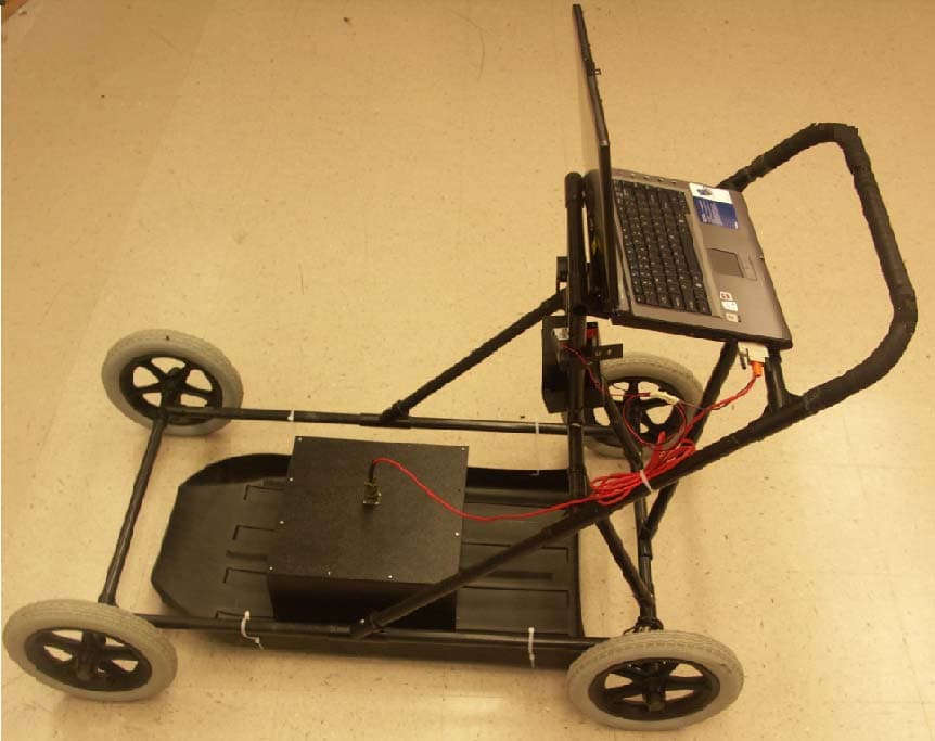
Click to zoom
Application Details
- Equipment Class
- UWB - Ultra Wideband Transmitter
- Date of Grant
- Mar 11, 2008
- Application Purpose
- Original Equipment
- Date of Application
- Nov 20, 2007
- Equipment Note
- Ground Penetrating Radar
- Frequency Range
- 200.00000000 - 460.00000000
- Company
- University of Houston
- Country
- United States
Documents & Files
Document Text
Text extracted from the exhibit documents filed with the FCC. Open a document above to read the original.
Users Manual
GPR SYSTEM USER GUIDE Subsurface Sensing Lab Electrical and Computer Engineering University of Houston 4800 Calhoun Road Houston, TX 77004 Phone: (713)743-4421 Fax: (713)743-4444 http://www2.egr.uh.edu/~elee52c/ GPR System User Guide University of Houston 2 Safety Instructions • This equipment has been tested and found to comply with the limits for a Class A digital device, pursuant to part 15 of the FCC Rules. These limits are designed to provide reasonable protection against harmful interference when the equipment is operated in a commercial environment. This equipment generates, uses, and can radiate radio frequency energy and, if not installed and used in accordance with the instruction manual, may cause harmful interference to radio communications. Operation of this equipment in a residential area is likely to cause harmful interference in which case the user will be required to correct the interference at his own expense. • Warning: Changes or modifications to this device not expressly approved by the party responsible for compliance could void the user’s authority to operate the equipment. FCC RF Exposure Compliance This GPR device has been tested and complies with the Federal Communications Commission (FCC) RF exposure limits for the General Population/Uncontrolled exposure environment. GPR System User Guide University of Houston 3 Table of Contents SAFETY INSTRUCTIONS ............................................................................................ 2 FCC RF EXPOSURE COMPLIANCE ......................................................................... 2 TABLE OF CONTENTS ................................................................................................ 3 TABLE OF FIGURES ..................................................................................................... 4 1. INTRODUCTION.................................................................................................... 5 1.1 MEASUREMENT PRINCIPLE ........................................................................................ 5 1.2 SYSTEM BLOCK DIAGRAM ......................................................................................... 6 1.3 PERFORMANCE DESCRIPTION .................................................................................... 6 2. HARDWARE INSTALLATION ............................................................................ 9 2.1 GPR DEVICE .............................................................................................................. 9 2.2 PHYSICAL CONNECTION OF GPR SYSTEM .................................................................. 9 3. SOFTWARE OPERATION AND DATA INTERPRETATION ...................... 11 3.1 INTERFACE DESCRIPTION ......................................................................................... 11 3.2 SOFTWARE OPERATION ........................................................................................... 13 3.2.1 Start a new measurement ............................................................................ 14 3.2.2 Open a saved file ......................................................................................... 14 3.3 DATA INTERPRETATION ........................................................................................... 15 4. TROUBLESHOOTING ........................................................................................ 17 GPR System User Guide University of Houston 4 Table of Figures Figure 1-1 Block diagram of the GPR system .................................................................. 6 Figure 1-2 GPR system in measurement configuration ..................................................... 7 Figure 2-1 Developed GPR ................................................................................................ 9 Figure 2-2 Physical connections of the GPR system ....................................................... 10 Figure 3-1 The interface for the GPRView software ....................................................... 11 Figure 3-2 GPR thickness over 1000 FT I-45 N. Conroe, Site 1091-1081 ..................... 16 Figure 4-1 Data acquisition card interface ....................................................................... 18 Figure 4-2 Contents in the dropdown window ................................................................ 19 Figure 4-3 Error message pops out when the DAQ card is not working ......................... 20 Figure 4-4 Error indicator of the DAQ card .................................................................... 21 Figure 4-5 make sure to delete the DAQ card ................................................................. 22 Figure 4-6 Empty device list at the interface ................................................................... 23 Figure 4-7 “Found New Hardware” wizard ..................................................................... 24 Figure 4-8 Install DAQ card driver .................................................................................. 25 Figure 4-9 Finish driver installaion.................................................................................. 26 Figure 4-10 Refresh the DAQ device .............................................................................. 27 Figure 4-11 DAQ device driver being reinstalled ............................................................ 28 Figure 4-12 DAQ device working properly ..................................................................... 29 GPR System User Guide University of Houston 5 1. INTRODUCTION The GPR technique is based on measurement of travel time and reflection amplitude of a short electromagnetic pulse wave that transmits through a medium. It provides continuous and nondestructive measurement compared to traditional highway detection methods, and is widely applied in thickness measurement, crack detection and pavement moisture content measurement. 1.1 Measurement principle A GPR system is mainly composed of six parts: a transm…
Text truncated - open the document above for the full version.
External Photos
External Photos Figure 1 top view Figure 2 bottom view Bottom Side Figure 3 view from down side Figure 4 view from up side Figure 5 Right hand side view Figure 6 Left hand side view Figure 7 GPR device with cable Figure 8 Electrical connection of the GPR system Figure 9 GPR application setup
ID Label/Location Info
FCC Label Format and Location Diagram 1. FCC label 2. Diagram University of Houston Model: 400 FCC ID: U7W400 This device complies with Part 15 of the FCC rules subject to the following two conditions: 1) This device may not cause harmful interference. 2) This device must accept all interference received, including interference that may cause undesired operation.
Internal Photos
1. Internal Photos 1.1. Receiver circuitry Fig.1 Top view of receiver PCBs Fig.2 Bottom view of receiver PCBs Figure 1 PCBs stacked up for installation Figure 2 Right hand side view of the stacked PCBs Figure 3 up side view of the stacked PCBs Figure 4 down side view of the stacked PCBs Figure 5 Circuit boards installed in the aluminum box Figure 6 the receiver box is sealed 1.2. Transmitter circuitry Figure 7 top view of the transmitter board Figure 8 Bottom view of the transmitter board 1.3. Antenna setup Figure 9 Bowtie antennas Figure 10 Electrical circuits are mounted on top of the antenna shielding box
Operational Description
Operational Description of Ground Penetrating Radar The impulse GPR is a device that is intentionally designed to directionally and locally radiate very small average electromagnetic power downwards into the ground to be detected. The developed GPR is composed of a pulse transmitter, a receiver, a transmitter antenna, a receiver antenna, and a laptop computer. Except the computer, all the components are installed in a plastic box. Once a 12VDC power is supplied, the GPR starts to work. To facilitate the FCC testing (Part 15), the GPR working environment and parameters are described below. When the GPR is at work, it is always setup on the ground surface to maximize the energy coupling into ground. The parameters of the developed GPR are given below: (1.) Dimension: 13.5 × 13.5 × 7.5 inch 3 ; (2.) Power supply: 12 VDC @ 370mA; (3.) Center frequency: 400MHz; (4.) Radiation pulse time duration: 2.5ns (5.) Radiation pulse P-P amplitude: 500mV; (6.) System Clock: 25KHz
Operational Description
DC voltages and current The circuits in this device ca n be divided into two parts: a receiver and a transmitter. The DC voltages to both parts are 12V; the current input the transmitter is 80mA and the current input the receiver is 250mA, making a total input current of 370mA. Power input to receiver 12VDC @ 290mA Power input to transmitter 12VDC @ 80mA
Parts List/Tune Up Info
III Parts List 1. Transmitter Parts List Item Number Quantity Ref. Number Value 1 1 C1 1u 2 1 C2 0.1u 3 1 C3 0.22u 4 1 C4 0.1u 5 1 C5 0.047u/250v 6 1 C6 0.047u/250v 7 1 C7 0.047u/250v 8 1 C8 0.5p 9 1 C9 470p 10 1 C10 4.7u 11 1 C11 0.1u 12 1 C12 33p 13 1 C13 15p/200v 14 1 C15 0.01u 15 1 C16 1u 16 1 C23 220p 17 1 C24 220p 18 1 R1 100k 19 1 R2 16.2k 20 1 R3 1.15M 21 1 R4 1.1 22 1 R6 10 23 1 R11 100 24 1 R14 36 25 1 R15 150 26 1 R16 150 27 1 R18 3.6k 28 1 R20 10 29 1 R23 510 30 1 L1 1000u 31 1 L5 50n 32 1 L6 33n 33 1 U2 MAX668 34 1 U3 FDS2070 35 1 U4 MAX626 36 1 Q3 NE94433 37 1 Q4 NE94433 38 1 D2 CMR1U-02M 39 1 D3 MA44769 2. Receiver parts List Item Quantity Reference Number Value 1 1 C4 4.7U/16V 2 45 C6,C15,C34,C37,C41,C56, C64,C65,C67,C70,C72,C75, C81,C85,C86, C88,C90,C95,C96,C97,C100,C102,C104,C108,C109,C113,C115,C118, C119,C121,C122,C123,C126,C128,C131,C133,C137,C138,C140,C147, C148,C149,C150,C152,C155 0.1u 3 6 C7,C8,C9,C25,C26,C27 33/200v 4 2 C10,C28 330p/200v 5 1 C11 .01u 6 3 C12,C18,C23 33p 7 3 C13,C19,C60 1n 8 5 C14,C21,C31,C49,C93 1u 9 1 C16 22 10 1 C17 6p 11 8 C20,C30,C33,C36,C52,C54, C79,C80 100p 12 1 C22 27p 13 4 C24,C42,C45,C83 5p 14 1 C29 0.1UF 15 5 C32,C48,C50,C59,C130 15p 16 2 C38,C39 STL 17 1 C43 2n 18 1 C47 0.2u 19 1 C51 10p 20 2 C53,C55 0.01u 21 2 C57,C82 220p 22 1 C58 0.1U/100V 23 11 C61,C62,C76,C87,C89,C92,C106,C107,C114,C116,C120 4.7u 24 22 C63,C66,C68,C69,C71,C73,C77,C84,C91,C94,C98,C99,C103,C105, C112,C117,C125,C129,C132,C145,C151,C153 10u 25 3 C74,C111,C134 20n 26 1 C110 10n 27 2 C124,C127 10u/16v 28 10 C135,C136,C139,C141,C142, C143,C144,C146,C154,C156 47U 29 1 DN1 HSMS-2822 30 1 D1 ma44769 31 1 D2 LM4050_5.0 32 1 D3 1N5401 33 1 D4 1N6265/TO 34 1 F1 smd100-2 35 3 J2,J16,J17 CON2 36 2 J3,J5 CON3 37 1 J4 CON4 38 4 J11,J12,J13,J14 mount 39 1 J15 CON14A 40 1 L1 33n 41 2 L2,L3 470n 42 10 L7,L8,L9,L10,L11,L13,L14,L15,L16,L17 10uH 43 1 L12 INDUCTOR 44 1 Q1 2n2369 45 1 Q2 BSS138 46 2 Q3,Q4 NE94433 47 1 Q5 TP0610 48 1 R1 100k/3mm 49 7 R3,R35,R36,R59,R65,R74, R75 10k 50 1 R4 300 51 1 R5 110 52 2 R6,R16 36 53 2 R7,R14 5.6k 54 4 R9,R12,R15,R69 3.6k 55 1 R13 620 56 2 R17,R23 20 57 2 R18,R29 510 58 3 R19,R27,R34 1k 59 1 R20 93k 60 6 R21,R33,R52,R54,R66,R72 100k 61 6 R22,R30,R46,R61,R135, R137 2k 62 2 R24,R25 500 63 1 R26 1.8k 64 6 R31,R38,R48,R51,R53,R68 100 65 1 R32 110K 66 2 R37,R133 5k 67 2 R39,R49 150 68 3 R40,R41,R47 20k 69 2 R42,R45 200 70 1 R43 40 71 1 R44 50 72 2 R50,R60 6.2k 73 1 R55 1.5k 74 2 R56,R73 200k 75 2 R67,R70 30k 76 1 SMA1 B5S 77 1 T1 2:2 78 1 U2 PICO12A48D 79 1 U6 AD8066 80 1 U7 AD783 81 1 U8 ad7533 82 1 U9 max627 83 2 U11,U34 LM318 84 1 U12 74HC74 85 3 U13,U29,U30 LF353 86 1 U14 LT1715 87 1 U17 AD8009 88 1 U22 AD825 89 1 U23 74HC14 90 2 U31,U32 4040 91 1 U33 12.8M 92 1 U35 UWR12/830 93 1 U36 NDL1212SC 94 1 U37 LM1085 95 1 U38 LM2990 96 1 U39 78L05
Test Report
Nemko Test Report: 5113RUS1 Applicant: University of Houston 4800 Calhoun Road Houston, TX 77004 USA Equipment Under Test: U7W400 (E.U.T.) In Accordance With: FCC Part 15, Subpart F, Paragraph 15.509 Ultra Wide Band Operation Ground Pentrating Radar Tested By: Nemko USA Inc. 802 N. Kealy Lewisville, TX 75057 TESTED BY: DATE: 15 October 2007 David Light, Senior Wireless Engineer APPROVED BY: DATE: 19 October, 2007 Mike Cantwell, Frontline Manager Total Number of Pages: 25 Nemko USA, Inc. FCC PART 15, SUBPART C, Paragraph 15.509 Ultra Wide Band Operation EQUIPMENT: U7W400 Test Report No.: 5113RUS1 Page 2 of 25 Table Of Contents SECTION 1. SUMMARY OF TEST RESULTS 3 SECTION 2. GENERAL EQUIPMENT SPECIFICATION 5 SECTION 3. RADIATED EMISSIONS 7 SECTION 4. TEST EQUIPMENT LIST 22 ANNEX A TEST DIAGRAMS 23 Nemko USA, Inc. FCC PART 15, SUBPART C, Paragraph 15.509 Ultra Wide Band Operation EQUIPMENT: U7W400 Test Report No.: 5113RUS1 Page 3 of 25 Section 1. Summary Of Test Results Manufacturer: The University of Houston Model No.: U7W400 Serial No.: Preproduction General: All measurements are traceable to national standards. These tests were conducted on a sample of the equipment for the purpose of demonstrating compliance with FCC Part 15, Subpart C, Paragraph 15.509 for ultra wide band operation. All tests were conducted using measurement procedure ANSI C63.4-2003. Radiated Emissions were made with the antenna positioned on the ground screen of an open area test site with the EUT positioned on a 4 foot by 4 foot by 4 foot dry sand pit New Submission Production Unit Class II Permissive Change Pre-Production Unit THIS TEST REPORT RELATES ONLY TO THE ITEM(S) TESTED. THE FOLLOWING DEVIATIONS FROM, ADDITIONS TO, OR EXCLUSIONS FROM THE TEST SPECIFICATIONS HAVE BEEN MADE. NONE See “ Summary of Test Data”. Nemko USA Inc. authorizes the above named company to reproduce this report provided it is reproduced in its entirety and for use by the company’s employees only. Any use which a third party makes of this report, or any reliance on or decisions to be made based on it, are the responsibility of such third parties. Nemko USA Inc. accepts no responsibility for damages, if any, suffered by any third party as a result of decisions made or actions based on this report. This report applies only to the items tested. Nemko USA, Inc. FCC PART 15, SUBPART C, Paragraph 15.509 Ultra Wide Band Operation EQUIPMENT: U7W400 Test Report No.: 5113RUS1 Page 4 of 25 Summary Of Test Data NAME OF TEST PARA. NO. RESULT Conducted Emissions 15.207 NA Pulse Repetition Frequency 15.509 Complies Definition of UWB 15.203(a)/15.209(a) Complies Radiated Emissions 15.509(d) Complies Radiated Emissions 15.509(e) Complies Peak Emission at f M 15.509(f) Complies Footnotes For N/A’s: The device is battery powered. Nemko USA, Inc. FCC PART 15, SUBPART C, Paragraph 15.509 Ultra Wide Band Operation EQUIPMENT: U7W400 Test Report No.: 5113RUS1 Page 5 of 25 Section 2. General Equipment Specification Frequency Range: Single Operating Frequency(ies) of Sample: 200 MHz to 460 MHz (10 dB BW) Tunable Bands: Single 20 dB Occupied Bandwidth: 260 MHz User Frequency Adjustment: None Integral Antenna Yes No Nemko USA, Inc. FCC PART 15, SUBPART C, Paragraph 15.509 Ultra Wide Band Operation EQUIPMENT: U7W400 Test Report No.: 5113RUS1 Page 6 of 25 Description of Device Tested Ground Penetrating Radar System System Diagram Refer to separate exhibit. Nemko USA, Inc. FCC PART 15, SUBPART C, Paragraph 15.509 Ultra Wide Band Operation EQUIPMENT: U7W400 Test Report No.: 5113RUS1 Page 7 of 25 Section 3. Radiated Emissions NAME OF TEST: Radiated Emissions PARA. NO.: 15.509(d)&(e) TESTED BY: David Light DATE: 12 October 2007 Minimum Standard: Para no. 15.509 Limits below 960 MHz (15.209 and 15.509): Frequency (MHz) Field Strength Limits (microvolts/m) Measuring RBW Distance (Meters) 0.009-0.490 0.490-1.705 1.705-30.0 30-88 88-216 216-960 2400/F(kHz) 24000/F(kHz) 30 100 150 200 1 kHz 10 kHz 10 kHz 100 kHz 100 kHz 100 kHz 300 30 30 3 3 3 Limits above 960 MHz (15.509) Frequency (MHz) E.I.R.P. (dBm) Measuring RBW Distance (Meters) 960-1610 1610-1990 1990-3100 3100-10600 Above 10600 1164-1240 1559-1610 -65.3 -53.3 -51.3 -41.3 -51.3 -75.3 -75.3 1 MHz 1 MHz 1 MHz 1 MHz 1 MHz 1 kHz 1 kHz 3 3 3 3 3 3 3 E.I.R.P limits converted from field strength during measurements per 15.521(g) Maximizing Emission Levels: The emissions were scanned from 30 MHz to 4000 MHz. For measurements below 960 MHz the emissions were made using a CISPR Quasi- peak detector IF BW = 100 kHz For Frequency above 960 MHz and outside the below frequency bands, the emissions were measured using EMI RMS detector, RBW=1MHz, VBW=10 MHz For frequencies fall inside 1164-1240 and 1559-1610 MHz, the emissions were measured using EMI RMS Detector, RBW = 1 KHz, VBW = 1 MHz Note: The above tests were performed with the EUT raised 5 cmfrom the ground as its intended use. The EUT was tested in 8 positions (every 45°) Test Results: Complies Measurement Data: See attached table(s). Nemko USA, Inc. FCC PART 15, SUBPART C, Paragraph 15.509 Ultra Wide Band Operation EQUIPMENT: U7W400 Test Report No.: 5113RUS1 Page 8 of 25 Test Data – Radiated Emissions Radiated Emissions Data CompleteXJob # : 5113Test # : REHE-01 PreliminaryPage1of11 Client Name :University of Houston EUT Name :Ground Coupled Radar EUT Model # :U7W400 EUT Part # : EUT Serial # : EUT Config. :Transmitting over sand pit Specification :CFR47 Part 15, Subpart B, Class B Reference :15.209/15.509 Rod. Ant. #:Temp. (deg. C) :22Date :10/11/07 Bicon Ant.#:1306Humidity (%) :40Time :9:00 Log Ant.#:759EUT Voltage :12Staff :David Light Bilog Ant.#:EUT Frequency :dcPhoto ID: Dipole Ant.#:Phase:0QP Bandwidth:120 KHz Cable#:1522Location:Sand Pit Preamp#:762Distance:3 Meters Limiter#:na Barometric pressure:1016 Atten #:na Detector#:1659 Meas.Ant.Atten.MeterAntennaPathRFCorrectedSpec.CR/SLPass Freq. Pol.ReadingFactorLossGainReadinglimitDiff.Fail (MHz)(H/V)(dB)(dBuV)(dB)(dB)(dB)(…
Text truncated - open the document above for the full version.
Contact Information
Applicant
Richard Liu(Professor, Lab Director)
Technical Contact
Nemko USA, Inc.Mike Cantwell
[email protected]972-436-9600
802 N Kealy Avenue · Lewisville, Texas · United States
Non-Technical Contact
Nemko USA, Inc.Michelle Furrow
[email protected]972-436-9600
Test Firm
Nemko USA, Inc.Tom Tidwell
Technical Specifications
| # | Rule Parts | Frequency Range | Power Output |
|---|---|---|---|
| 1 | 15F | 200 MHz - 460 MHz | - |