U870006RFID Reader Module
KEBA Industrial Automation GmbH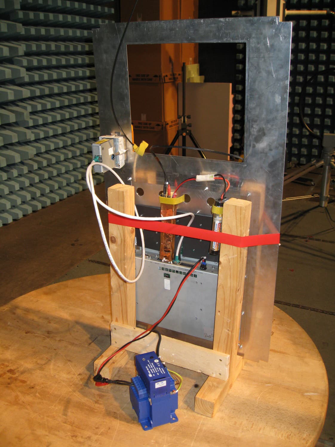
Click to zoom
Application Details
- Equipment Class
- DXT - Part 15 Low Power Transceiver, Rx Verified
- Date of Grant
- Oct 22, 2015
- Application Purpose
- Original Equipment
- Date of Application
- Oct 22, 2015
- Equipment Note
- RFID Reader Module
- Frequency Range
- 13.55300000 - 13.56700000
- Country
- Austria
Documents & Files
Document Text
Text extracted from the exhibit documents filed with the FCC. Open a document above to read the original.
Users Manual
RFID-Module Introduction Kemro K2 XE 020/C RFID-Module Internal Technical Documentation V 1.0 Introduction XE 020/C List of changes Version changed from / to Date Description Modified by 1.0 10-2015 Created (derived from XE 020/A) dbg RFID-Module Introduction Contents 1 Introduction ................................................................................................................... 5 1.1 Purpose of the document ..................................................................................... 5 1.2 Audience and prerequisites ................................................................................. 5 1.3 Intended use ........................................................................................................ 5 1.4 Notes on this document ....................................................................................... 6 1.4.1 Contents of document .............................................................................. 6 1.4.2 Not contained in this document ................................................................ 6 1.5 Documentation for further reading ....................................................................... 7 2 Safety notes .................................................................................................................. 8 2.1 Representation .................................................................................................... 8 3 Product overview .......................................................................................................... 9 3.1 Summary ............................................................................................................. 9 3.1.1 Range and detection .............................................................................. 10 3.2 RFID module before installation ......................................................................... 10 3.3 RFID module after installation ............................................................................ 11 4 Assembly and installation notes ................................................................................ 12 4.1 Space requirements ........................................................................................... 12 4.2 Installing the RFID module ................................................................................. 12 5 Connections and wiring ............................................................................................. 14 5.1 EMC and wiring guidelines ................................................................................ 14 5.1.1 Personal safety ...................................................................................... 14 5.1.2 Why EMC-aware wiring? ........................................................................ 14 5.1.3 Which EMC measures must be taken? ................................................... 14 5.2 Power supply ..................................................................................................... 14 5.3 XE 020/C module interfaces .............................................................................. 15 5.3.1 Internal Connector for coaxial antenna cable.......................................... 15 5.3.2 Internal Connector for status LED .......................................................... 15 5.3.3 XE 020/C module RJ45 socket ............................................................... 15 5.4 Cables ............................................................................................................... 16 5.4.1 Coaxial antenna cable ............................................................................ 16 5.4.2 Connector cable for RFID status LED..................................................... 16 5.4.3 Connector cable for RFID module / OP 3xx ............................................ 16 6 Configuration .............................................................................................................. 17 6.1 RFID module DIP switch .................................................................................... 17 7 Status display.............................................................................................................. 18 7.1 RFID status LED ................................................................................................ 18 7.1.1 Boot-time behaviour ............................................................................... 18 8 Maintenance and repair notes .................................................................................... 19 Introduction XE 020/C 8.1 Maintenance ...................................................................................................... 19 8.2 Repair ................................................................................................................ 19 8.2.1 Packaging and shipping ......................................................................... 19 8.3 Waste disposal .................................................................................................. 19 9 Accessories and spares ............................................................................................. 20 10 Technical specification ............................................................................................... 21 11 Relevant EC directives and applicable standards .................................................... 22 11.1 EC directives ..................................................................................................... 22 11.2 Standards .......................................................................................................... 22 11.2.1 Validating conformance to the R&TTE directive .................................... 22 11.2.2 Other standards .................................................................................... 22 11.2.3 USA standards ..................................................…
Text truncated - open the document above for the full version.
Cover Letter(s)
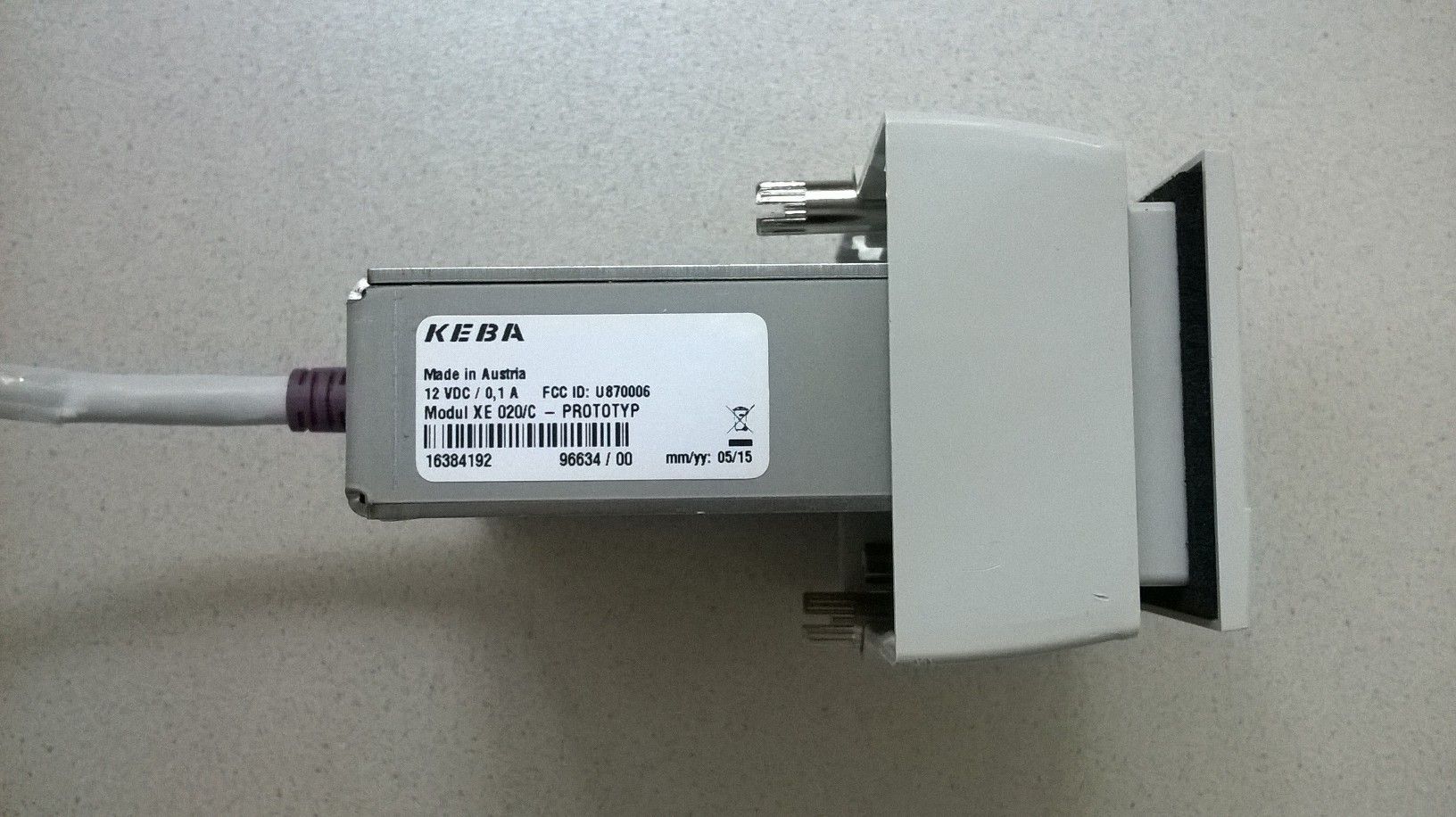
Coverletter: KEBA AG wants to get FCC-Certification for the following product: RFID reader module XE020/C. The unit will get the following FCC-ID: U870006 List of documents: Exhibit Thema File Exhibit 01 Label and placement XE020C_Typenschild.jpg Exhibit 02 Not needed -------------------- Exhibit 03 External Photos extern15-165.pdf * Exhibit 04 Block Diagrams xe020_c_block.pdf * Exhibit 05 Schematic Diagrams X110_ANT_schematics.pdf XE020_schematics.pdf Exhibit 06 Testreport FG15-165.pdf Exhibit 07 Test Set-up Photos setup15-165.pdf Exhibit 08 User Manual XE020C_TDEN.pdf Exhibit 09 Internal Photos intern15-165.pdf Exhibit 10 Informations -------------------- Exhibit 11 RF exposure -------------------- * Exhibit 12 Operational Description xe020_c_decription.pdf Exhibit 13 Cover letter Request for confidentiality This file Request_for_Confidentiality_Keba_XE020_C.doc.pdf For the Exhibits marked with ‘*’ KEBA AG requested Confidentiality according to 47 CFR 0.457 and 0.459 of the FCC rules because these are sensitive parts owned by this company and include much of Know-How or sensitive data, it will not be provided to the public. The labelling on some photos may be not the actual status. The correct labelling you can see on the label and placement photo in Exhibit 1.
Cover Letter(s)
KEBA AG Gewerbepark Urfahr, A-4041 Linz, phone: +43 732 7090-0, fax: +43 732 730910, mail: [email protected], www.keba.com DVR 0485829, UID-Nr. ATU 47390407, Firmenbuchgericht Linz FN 184376 t KEBA AG, Gewerbepark Urfahr A-4041 Linz Federal Communication Commission Equipment Authorization Division, Application Processing Branch 7435 Oakland Mills Road Columbia, MD 21046 2015-07-28 Subject: Permanent Request for Confidentiality FCC ID: U870006 Product: XE 020/C TO WHOM IT MAY CONCERN Pursuant to Paragraphs §0.457 and 0.459 of the Commission’s Rules (47 CFR) and Section §552(b)(4) of the Freedom of Information Act, for the product stated above KEBA requests that the following information be withheld from public inspection: 1. Circuit diagrams, BOM (Bill of Materials), and PCBs submitted as Equipment Authorization Electronic Filing attachment: schematics, assembly, layers 2. Block diagram and operational description submitted as Equipment Authorization Electronic Filing attachment: Block diagramm and Operational description The above exhibits contain detailed system and equipment description and related information about the product, which KEBA considers to be proprietary and confidential and which otherwise would not be released to general public. This information could be of unfair benefit to our competitors regarding the design of our product. If you have any question, please feel free to contact us at the address shown below. Sincerely, Dobersberger Markus EMC Engineer
External Photos
Appendix 2 Photodocumentation Description: Module in test setup view #1 Division Medical Technology/ Communication Technology/ EMC Department: FG Test report reference: M/FG-15/165 Page: 1 of 14 Date: 20.10.2015 checked by: _______ Appendix 2 Photodocumentation Description: Module in test setup view #2 Division Medical Technology/ Communication Technology/ EMC Department: FG Test report reference: M/FG-15/165 Page: 2 of 14 Date: 20.10.2015 checked by: _______ Appendix 2 Photodocumentation Description: Front view (Antenna) Division Medical Technology/ Communication Technology/ EMC Department: FG Test report reference: M/FG-15/165 Page: 3 of 14 Date: 20.10.2015 checked by: _______ Appendix 2 Photodocumentation Description: Backside view #1 Division Medical Technology/ Communication Technology/ EMC Department: FG Test report reference: M/FG-15/165 Page: 4 of 14 Date: 20.10.2015 checked by: _______ Appendix 2 Photodocumentation Description: Backside view #2 Division Medical Technology/ Communication Technology/ EMC Department: FG Test report reference: M/FG-15/165 Page: 5 of 14 Date: 20.10.2015 checked by: _______
Internal Photos
Appendix 2 Photodocumentation Description: Case opened Division Medical Technology/ Communication Technology/ EMC Department: FG Test report reference: M/FG-15/165 Page: 7 of 14 Date: 20.10.2015 checked by: _______ Appendix 2 Photodocumentation Description: Antenna PCB view #1 Division Medical Technology/ Communication Technology/ EMC Department: FG Test report reference: M/FG-15/165 Page: 8 of 14 Date: 20.10.2015 checked by: _______ Appendix 2 Photodocumentation Description: Antenna PCB view #2 Division Medical Technology/ Communication Technology/ EMC Department: FG Test report reference: M/FG-15/165 Page: 9 of 14 Date: 20.10.2015 checked by: _______ Appendix 2 Photodocumentation Description: Mainboard PCB view #1 Division Medical Technology/ Communication Technology/ EMC Department: FG Test report reference: M/FG-15/165 Page: 10 of 14 Date: 20.10.2015 checked by: _______ Appendix 2 Photodocumentation Description: Mainboard PCB view #2 Division Medical Technology/ Communication Technology/ EMC Department: FG Test report reference: M/FG-15/165 Page: 11 of 14 Date: 20.10.2015 checked by: _______
Test Setup Photos
Appendix 2 Photodocumentation Description: Label of Panel used as Power Supply Division Medical Technology/ Communication Technology/ EMC Department: FG Test report reference: M/FG-15/165 Page: 12 of 14 Date: 20.10.2015 checked by: _______ Appendix 2 Photodocumentation Description: Test setup view #1 Division Medical Technology/ Communication Technology/ EMC Department: FG Test report reference: M/FG-15/165 Page: 13 of 14 Date: 20.10.2015 checked by: _______ Appendix 2 Photodocumentation Description: Test setup view #2 Division Medical Technology/ Communication Technology/ EMC Department: FG Test report reference: M/FG-15/165 Page: 14 of 14 Date: 20.10.2015 checked by: _______
Contact Information
Applicant
Manuel Kaufmann(Dipl.-Ing.)
Test Firm
TUV AUSTRIA GMBHWilhelm Seier
Technical Specifications
| # | Rule Parts | Frequency Range | Power Output | Tolerance |
|---|---|---|---|---|
| 1 | 15C | 13.553 MHz - 13.567 MHz | - | 22.8600000000 ppm |