Text extracted from the exhibit documents filed with the FCC. Open a document above to read the original.
Quick Guide Please read this guide carefully before using this product and properly keep the guide for future use. Auto Audio & Video Entertainment System No.A00 A-M VOL+ VOL- NAV ★★★★ Copyright The copyright of this manual is reserved by our company. All rights are reserved. This manual may not be copied, reproduced or translated in whole or in part without the express written permission of our company. Our company reserves the right to improve the product, and its hardware and software. This manual is an operating guide, but not the warranty of the product. Our company doesn't guarantee the contents included in this manual. Since we adhere to the strategy of sustainable development, printing error in the manual, incompliance with latest materials, software upgrade, and product improvement may be performed at any time. The product is subject to change without further notice, and revision will be directly edited to the manual of new edition. Our company reserves the right of final interpretation for the manual. PrecautionsPrecautions To ensure the traffic safety and avoid contravening the traffic regulations, do not watch any program or operate the system during driving. For safety and correction operation of the product, the product shall be installed by professional. Do not disassemble or repair the product by yourself to avoid an accident or damage to the product. To avoid electric shock, damage and fire resulting from short-circuit, do not place the product in water or places where are wet. Since the screen of the product adopts precision electronic structure, do not knock the TFT display to avoid damage to the product. As for car backing, this system works simply as an assistant tool. Our company is not responsible for any potential car backing accidents. The failure diagnosis of for car can offer suggestion for car repair, and the failure information indicated should be determined by a professional maintenance center. Tire pressure monitoring system can monitor the pressure and temperature of the tire, and helps to reduce the risk of tire burst. However, tire burst may still occur. Under normal tire pressure or temperature, tire burst can be caused by wear of tire and the perfection degree. Therefore, the monitoring data of the system is only for reference, and you should check the tire status in time. This system is designed for 12V power supply system of the car (cathode is connected to ground). Do not install the system directly to a car not powered by 12V power supply; otherwise, damage to the system may occur. 1 NOTE Trademark Licence: In order to use the product correctly and safely, please read this manual carefully. Specification and design due to technical improvement are subject to variation without notice! Please read this manual carefully before using this product and properly keep the Manual for future use. Remark: The above symbol indicates that this product hasn't any harmful material or elements, it is environmental and recyclable, and shouldn't be littered at random. ①Manufactured under license from Dolby Laboratories; ②Dolby and the “double-D” symbol are trademarks of Dolby Laboratories.“” 2 Brief Introduction This product is a multi- function GUI car AV entertainment system specially designed by us. combines DVD player, radio, Bluetooth communication, navigation (optional), TV (optional), IPod player (externally plugged) and audio power amplifier together. The system adopts dedicated slot-loading car DVD chip, which can play DVD, VCD, MP3, WMA, MPEG4, JPEG, etc.. In addition, the system adopts high-sensitivity FM and AM digital tuner making you master the world's trends and financial information at any time and any place while you are in your car; with 16:9 6.5” extra-clear TFT LCD, which can adjust brightness of the screen automatically according to the light intensity of outside. The screenbut also offering a best visual status all the time as well. With optional reverse radar, reverse camera, disc changer, NAV, AV and other interfaces for auxiliary functions (reverse radar, reserve camera, NAV, disc changer, etc.), you can use these functions to realize more functions. The structural dimensions of the system conform to the installation dimensions of ISO TWO DIN. Car electronic product is specially designed, fully intelligent, humanized, and featuring GUI operation; featuring OSD menu, various functions can be realized through function keys on the panel and touch screen, thus realizing perfect HMI and meeting your requirements of comfort. If your cell phone is a bluetooth cell phone, you can answer your call through the system without picking up your phone; with double zone functions, people at rear row can be satisfied. To correctly install and use the system, please read this manual carefully to understand operations of common functions quickly. Thank you for purchasing our high-quality car electronic product. It angle can be adjusted. Not only wide angle view, It has outboard USB card port, when you insert U-disccard, it can skim and play the audio and picture in the portable hard disc. 3 Product Functions Built-in Functions: Built-in RADIO,DVD player,TV (if the host unit has a built-in TV module) navigation, ,and high power amplifier.(external navigation box isoptional). Bluetoothhand-freedisplay DVD Player: It could play DVD/VCD/CD/MP3/WMA/JPEG /MPEG4 disc. Radio Receiving: High sensitive AM/FM receiving, could restore 24 stations. Bluetooth Hand-free: Supports bluetooth hand-free communication and bluetooth play function. USB Port: It support USB 1.1 and able to play MP3,WMA audio and skim picture. 4 SD Card Port The host unit with built-in NAV module Possess double SD card port, Separately plays audio and video files as well as the stored navigation map data. iPod Play: It supports music and video from iPod.(The transfering wire of our company is necessary). The host unit without built-in module Possess single SD card ports NAV eparately plays audio and …
Text truncated - open the document above for the full version.
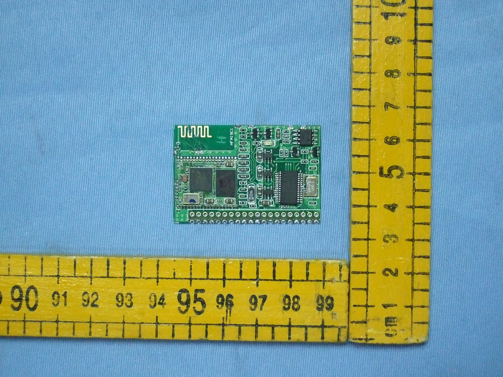
Page 27 of 31 FCC ID: U8FSSHBSFCC03 Anbotek Compliance Laboratory Limited Report No.200711676F Figure 1 The EUT-Overall View Figure 2 The EUT-Back View
FCC ID Label Sample for FCC ID: U8FSSHBSFCC03 FCC ID: U8FSSHBSFCC03 This device complies with Part 15 of the FCC Rules. Operation is subject to the following two conditions: 1. This device may not cause harmful interference, and 2. This device must accept any interference received, including interference that may cause undesired operation.
The proposed Label Location on EUT Proposed FCC ID Label Location
Page 28 of 31 FCC ID: U8FSSHBSFCC03 Anbotek Compliance Laboratory Limited Report No.200711676F Figure 3 The EUT-Front View Figure 4 The EUT-Back View Page 29 of 31 FCC ID: U8FSSHBSFCC03 Anbotek Compliance Laboratory Limited Report No.200711676F Figure 5 The EUT-Front View Figure 6 The EUT-Back View Page 30 of 31 FCC ID: U8FSSHBSFCC03 Anbotek Compliance Laboratory Limited Report No.200711676F Figure 7 PCB of the EUT-Front View Figure 8 PCB of the EUT-Back View Page 31 of 31 FCC ID: U8FSSHBSFCC03 Anbotek Compliance Laboratory Limited Report No.200711676F Figure 9 PCB of the EUT-Front View Figure 10 PCB of the EUT-Back View
11 22 33 44 D D C C B B A A Title Number Revision Size A4 Date: 2006/10/22 Sheet of File: H:\PCB LAYOUT\..\HFA19C1.SchDoc Drawn By: HFA19C1 C3 C4 321 54 VIN CE/MODE VSS NCVOUT U4SOT235 321 54 VIN CE/MODE VSS NCVOUT U5SOT235 321 54 VIN CE/MODE VSS NCVOUT U6SOT235 0805 C11 0805 C12 0805 C13 0805 C14 VPA VCC 3.3V VPA VCC VPA 1.8V VPA 3.3V VPA MUTE UTX MIC+ MIC- SPKR+ SPKL+ SPKL- SPKR- MUTE ETR ENDK LED0LED1 SPI_CSB SPI_MISO SPI_CLK SPI_MOSI STX SRX 1234567891011121314151617181920 J1J-H20(PITCH:2.0mm) MIC+ MIC- MIC_LPMIC_LN BTP BTP 1234 5678 24LC16U2SO-8 SRX STX URX MCK MDT ETR ENDK LED1LED0 LDPRDPBTP Y1 C1 R1 VCC R5 R6 MCKMDT VCC 123456789 10111213141516171819 20212223242526272829303132333435363738 39 40 41 42 43 44 45 SPK_LEFT_NSPK_LEFT_PSPK_RIGHT_NSPK_RIGHT_PGNDMIC_LEFT_PMIC_LEFT_NMIC_RIGHT_PMIC_RIGHT_NAIOOUART_RTSUART_CTSUART_TXUART_RXGND1.8V3.3/1. 8VPIO6PIO7 GNDPIO5PIO4 SPI_MOSISPI_MISO SPI_CLKSPI_CSB RESET PIO11 PIO3PIO9 PIO10 VDD_PA PIO1 PIO0PIO8 RF_IN GND RF/OUT USB_DP USB_DN PCM_CLK PCM_OUT PCM_SYNC PCM_IN PIO2 CG-MUC-04 U3 0603 C5 0603 C6 0603 C7 0603 C8 SPKL- SPKL+ SPKR- SPKR+ MIC_LP MIC_LN C9 C10 URX 1.8V3.3V R7 Q3 VCC RDP SPI_MOSISPI_MISOSPI_CLKSPI_CSB 0603 C17 R13 3.3V R11 R12 D1 0805 Q4 VCC LDP L1 E1 A0A1A2VSS SDA SCL WP VCC R2 Q1 Q2 R4 R10 R8R9 R3 1206 C2 + R14 C19 C18 123456789 10 19202122232425262728 11121314 18171615 PB5/AN5PB4/AN4PA3/PFDPA2PA1PA0PB3/AN3PB2/AN2PB1/AN1PB0/AN0VSSPC0PC1PC2 PC3 PC4 PD0/PWM0 PD1/PWM1 RES VDD OSC1OSC2 PA7/SCL PA6/SDA PA5/INT PA4/TMR PB7/AN7PB6/AN6 U1 HT46R23(209mil)
Page 1 of 31 FCC ID: U8FSSHBSFCC03 Anbotek Compliance Laboratory Limited Report No.200711676F FCC TEST REPORT for Coagent Electronic S&T Co., Ltd. Car DVD/TV/Radio/Bluetooth/GPS(Bluetooth portion only) Model No.: CA1615G, CA3023, CA3025, CA3028, CA3032, CA3126, CA3104, CA3116, CA3119, CA3120, CA3121, CA3111, CA3122, CA3033, K130, K170G, K317, K318, K319, K320, K322, K323, K325, K326, K327, K328, K329, K330, K331, K332 Report Number : 200711676F Date of Test : Dec.03~14, 2007 Date of Report : Dec.17, 2007 Prepared for : Coagent Electronic S&T Co., Ltd. Address : No. 15, Kouan Road, Sanshui District, Foushan, Guangdong, China Tel: (86) 757-87802939 Fax: (86) 757-87821585 Prepared By : Anbotek Compliance Laboratory Limited Address : 2/F, Langfeng Building, Kefa Road North, Hi-tech Industrial Park, Nanshan District, Shenzhen 518057, China Tel: (86) 755-26014771 Fax: (86) 755-26014720 Page 2 of 31 FCC ID: U8FSSHBSFCC03 Anbotek Compliance Laboratory Limited Report No.200711676F TABLE OF CONTENT Description Page Test Report 1. GENERAL INFORMATION .........................................................................................................4 1.1. Description of Device (EUT)....................................................................................................................4 1.2. Description of Test Facility ......................................................................................................................5 1.3. Measurement Uncertainty.........................................................................................................................5 2. MEASURING DEVICE AND TEST EQUIPMENT.................................................................... 6 3. TECHNICAL TEST ........................................................................................................................ 7 3.1. Summary of Test Results..........................................................................................................................7 3.2. Antenna Requirement ...............................................................................................................................7 4. CONDUCTED POWER LINE TEST............................................................................................ 8 4.1 Test Equipment..........................................................................................................................................8 4.2 Test Procedure ...........................................................................................................................................8 4.3 Test Setup ..................................................................................................................................................8 4.4 Configuration of the EUT..........................................................................................................................9 4.5 EUT Operating Condition .........................................................................................................................9 4.6 Conducted Power Line Emission Limits ...................................................................................................9 4.7 Conducted Power Line Test Result ...........................................................................................................9 5. FCC PART 15.247 REQUIREMENTS FOR FHSS SYSTEMS................................................ 10 5.1 Test Equipment........................................................................................................................................10 5.2 Test Procedure .........................................................................................................................................10 5.3 Test Setup ................................................................................................................................................11 5.4 Configuration of the EUT........................................................................................................................11 5.5 EUT Operating Condition .......................................................................................................................11 5.6 Limit ........................................................................................................................................................11 5.7 Test Result ...............................................................................................................................................11 6. TRANSMITTER SPURIOUS RADIATED EMISSION AT 3 METERS ................................ 21 6.1 Test Equipment........................................................................................................................................21 6.2 Test Procedure .........................................................................................................................................21 6.3 Test Setup ................................................................................................................................................21 6.4 Test Procedure .........................................................................................................................................21 6.5 Test Procedure .........................................................................................................................................22 6.6 Limit ........................................................................................................................................................22 6.7 Test Result ...............................................................................................................................................23 7. RF EXPOSURE REQUIREMENTS............................................................................................ 24 7.1 Test Equipment.......................................................................…
Text truncated - open the document above for the full version.
Page 25 of 31 FCC ID: U8FSSHBSFCC03 Anbotek Compliance Laboratory Limited Report No.200711676F 8. PHOTOGRAPH 8.1. Photo of Radiation Emission Test Page 26 of 31 FCC ID: U8FSSHBSFCC03 Anbotek Compliance Laboratory Limited Report No.200711676F APPENDIX I (Photos of EUT) Page 27 of 31 FCC ID: U8FSSHBSFCC03 Anbotek Compliance Laboratory Limited Report No.200711676F Figure 1 The EUT-Overall View Figure 2 The EUT-Back View Page 28 of 31 FCC ID: U8FSSHBSFCC03 Anbotek Compliance Laboratory Limited Report No.200711676F Figure 3 The EUT-Front View Figure 4 The EUT-Back View Page 29 of 31 FCC ID: U8FSSHBSFCC03 Anbotek Compliance Laboratory Limited Report No.200711676F Figure 5 The EUT-Front View Figure 6 The EUT-Back View Page 30 of 31 FCC ID: U8FSSHBSFCC03 Anbotek Compliance Laboratory Limited Report No.200711676F Figure 7 PCB of the EUT-Front View Figure 8 PCB of the EUT-Back View Page 31 of 31 FCC ID: U8FSSHBSFCC03 Anbotek Compliance Laboratory Limited Report No.200711676F Figure 9 PCB of the EUT-Front View Figure 10 PCB of the EUT-Back View
| # | Rule Parts | Frequency Range | Power Output |
|---|---|---|---|
| 1 | 15C | 2.40 GHz - 2.48 GHz | 80.00 mW |

CAR DVD/TV/RADIO/BLUETOOTH-BLUETOOTH PORTION
Equipment Class
DSS - Part 15 Spread Spectrum Transmitter