U8JN-4QRadio Control System
Guangzhou Chiyuan Electronic Co., Ltd.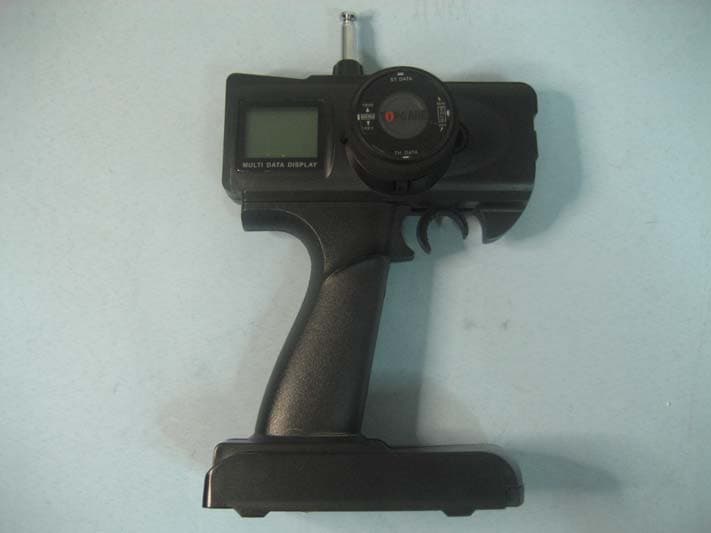
Click to zoom
Application Details
- Equipment Class
- TNB - Licensed Non-Broadcast Station Transmitter
- Date of Grant
- Jul 11, 2007
- Application Purpose
- Original Equipment
- Date of Application
- Jul 11, 2007
- Equipment Note
- Radio Control System
- Frequency Range
- 72.01000000 - 72.99000000
- Country
- China
Documents & Files
Document Text
Text extracted from the exhibit documents filed with the FCC. Open a document above to read the original.
Users Manual
TPCAREOTPCAREO Guangzhou Chiyuan Electronic Co., Ltd Add: 2/F., No. 1 Bldg., Boyi Industrial Garden, 4th Gongye Rd. Zhicun, Dashi Street, Panyu Dis., Guangzhou, China P.C.:511430 Tel: +86-20-34796226;34797226 Fax: +86-20-34796116 Website: www.chiyuan.net E-mail: [email protected] Thank you for purchasing our‘TPCARE’R/C system. Before using, read this manual carefully. O PPM/FM Radio Control System Introduction Manual RADIO CONTROL SYSTEM N-4Q R/C R/C Introduction Manual 3.1 Handling Procedure For Batteries 7 ! Battery Replacement 1.Remove the battery cover from the transmitter by sliding it in the direction of the arrow . 2. Remove the used batteries. 3.Load the new AA size batteries. Pay very close attention to the polarity marking and reinsert accordingly. 4 .Slide the battery cover back onto the case. ! Caution Always be sure your reinsert the batteries in the correct polarity order. If the batteries are loaded incorrectly, the transmitter may be damaged. When the transmitter is not used , always remember to remove the batteries. If the batteries do happen to leak, clean the batteries case and contacts thoroughly. Make sure the contacts are free of corrosion. ! Battery Disposal Some countries require special handling of used of batteries ,please contact the agencies responsible for recycling hazardous wastes in your local area. ! Battery low voltage alarm indicator. R/C Introduction Manual Caution N-4Q) Transmitter Chart N-4Q)Transmitter Chart N-4Q )Transmitter Chart N-4Q )m 1.1 (LCD(2CH) 1.2 (LCD(3ch) 1.2 Menu 1.3 Trim 2.1 (LED(2CH) 2.2 (LED enu 3.1 Handling Procedure For Batteries 4.1 Connection between Receiver and Servos Technology Data 1 2 3 4 5 6 6 7 8 8 4.D/R Knob(20%~100%) Clockwise, steering servo travel will be increased. Anticlockwise, steering servo travel will be decreased. 5.ST.&TH. Trim Adj. Push “ST.&TH. Trim Adj.” button up or down,Steering Trim&Throtter Trim in the middle. 20% 100% R/C Introduction Manual 1.4 Trim 5 !Please start the motor or the engine while marking the adjustment of these settings. 1 .Connect the receiver, servos, and other components and then turn on the power switches to transmitter and receiver. 2.Be sure the Steering trim and Throttle trim on the transmitter are at their neutral position. 3.When turning on the transmitter, please make sure the transmitter antenna is completely extended. Turn on the transmitter before turning on the receiver, while turn off the receiver before turning off the transmitter. Steering Trim Steering neutral adjustments can be made by moving the steering trim knob to the left or the right. !Racers Tip Always check and be sure the servo is at its neutral position before installing a servo. Adjust the servo horn hole position and linkage so both are parallel. When a servo saver is used place it as closer to center position as possible. Be sure the steering trim on the transmitter at the neutral position. !Trim Operation And Maximum Trav. Changing the trim can effect the overall settings, when adjustments are made with the trims, please recheck your installation for maximum servo travel.(Sreeting EPA right side and left side ). !When Trim movement goes to extremes That means if you make a lot of trim movement to get a servo to the neutral position, please reposition the servo horn or servo saver on the servo and inspect your linkage installation. Throttle Trim Throttle neutral adjustments can be made by moving the throttle trim to the left or the right. ! Racers Tip When using a electronic speed control, please set the throttle trim to neutral and make adjustments to the speed control. On a gas powered model, set the trim to neutral and adjust the linkage to the point where carburetor is fully closed in accordance with the engine instruction manual. ! Trim Operation and Travel Trim adjustments will effect the overall servo travel, so please check the (back-ward) movement after the adjustment ! When trim movement is goes to extremes That means if you make a lot of the trim movement to get the servo to the neutral position, please recenter the servo horn closer to the neutral position and inspect your throttle linkage. Steering Trim Throtter Trim R/C Introduction Manual 2 !When the voltage is lower than 8.6V,the voltmeter will flash with low voltage alarming. !ST. D/R Knob(20%~100%) Clockwise, steering servo travel will be increased. Antenna Menu SW Steering Wheal Crystal(Tx) Power SW Throtter Trim LCD Steering D/R Knob Steering Trim Throtter Trigger Battery Cover Charging Jack 1.1 (2CH)N-4Q(LCD) Transmitter Chart Moudle Steering D/R 油门微调显示 Mode LOGO Channel Voltage 2CH Antenna Menu SW Steering Wheal Crystal(XTAL) Power SW Throtter Trim LCD Ch3 Knob Steering Trim Throtter Trigger Battery Cover Charging Jack R/C Introduction ManualR/C Introduction Manual 43 1.3 Menu !Push “MENU” button down to access “FUNCTION”. !Push “MENU” button up to access “SUB. TRIM”. !Push “ST. DATA” button left or right, the “ST.” arrow in LCD will move accordingly. The “ST.” arrow will keep moving if the button is pushed continuously. !Push “TH. DATA” button left or right, the “TH.” arrow in LCD will move accordingly. The “TH.” arrow will keep moving if the button is pushed continuously. !Push “MENU” button up to exit and “SUB TRIM” will be saved simultaneously. 1.2 (LCD)N-4QTransmitter Chart(3CH) Moudle Ch3 油门微调显示 Mode LOGO Channel Voltage 3CH 2. SUB TRIM ST. ST. TH. TH. [Sub.Trim][Sub.Trim] REV. FUN. TRIM FUN. STOR FUN EXIT REV. FUN. TRIM FUN. STOR FUN EXIT [FUNCTION] A[FUNCTION] A >> !Push “MENU” button down to access “FUNCTION”. !Push “MENU” button up to access “STOR FUN”. !Push “TH. DATA” button right or left, select mode memory . !Pushing “MENU” button up to exit and “STOR FUN” will be saved simultaneously. 3. STOR MODEL [STOR MODEL][STOR MODEL] REV. FUN. TRIM FUN. STOR FUN EXIT REV. FUN. TRIM FUN. STOR FUN EXIT [FUNCTION] A[FUNCTION] A >> A B C D E F G H I J K L A [REV][REV] REV. FUN. TRIM FUN. STOR FUN EXIT REV. FUN. TRIM FUN. STOR FUN EXIT…
Text truncated - open the document above for the full version.
Block Diagram
123456 A B C D 654321 D C B A Title NumberRevisionSize B Date:19-Jan-2007Sheetof File:C:\Program Files\Design Explorer 99 SE\Examples\POWER5.DDBDrawn By: CPU THRO CH ST CH LCD RF TRANSTOR
External Photos
FRONT VIEW OF EUT BACK VIEW OF EUT LEFT VIEW OF EUT RIGHT VIEW OF EUT TOP VIEW OF EUT BOTTOM VIEW OF EUT
ID Label/Location Info
FCC ID: U8JN-4Q
Internal Photos
INTERANAL PHOTO OF TX - 1 INTERNAL PHOTO OF TX - 2
Operational Description
N-4Q Opeartion Description 一. Principle Chart: 1. Controlling: 2. Principle Analysis: The signal of the external potentiometer is input to the micro controller through low pass filter, and the micro controller will AD sample the input signal and code it. The coded baseband signal will be output by the second angle of U300. 3. RF: 4. Principle Analysis: The baseband signal output by the second angle is sent to RF module, modulated at high frequency carrier and then radiated out through antenna. for each channel through the above decoding circuit.
Schematics
1 2 3 4 56 A B CD 6 5 4 3 2 1 D C B A DIMENSIONAL SCALE DESIGNEDAPPROVEDSHEETSHEET Q'TYPLATESIZE VER.VER. PCB NO. MATERIAL/FINISHMATERIAL/FINISHMATERIAL/FINISHCREATE DATEMODEL CODE/NAMEPARTS CODE/NAME Guangzhou Chiyuan Electronic Co., LTD. B 枪控发射机 _FM 72 MHz V1.0 25/04/2007 ZKY C227103 Q2002SC2314F R2123.9K C210102 C231103 31 46 2 T2053:1 C22433P CV2002sc3356 V200C9018 R231100 R20322 C222103 R2023.9K C22133P R209680 R200220K 31 46 2 T2003:1 C21833PC21656P Y172MHz C2303~35P R20610K R201220 C206103 W20010K C204103 L2001.5uH D20302CZ6.8Y R2132.2 C21733P 31 46 2 T2023:1 C2197P R204390 BAT1(J100)UM-3X8(12V) A 1 B 2 J101CON3 VI GND VO U10078M05 C101104 C104103 C104103 123 J101SW1 123 SW302N/R 123 SW303N/R +5V 123 J3015KB C301 104 C22956P ANT1 3 1 4 6 2 T2036T C21156P 3 1 4 6 2 T2046T C2124.7u D200kv1471 C28856P PD3 1 PD4 2 GND 3 VCC 4 GND 5 VCC 6 PB6 7 PB7 8 PD5 9 PD6 10 PD7 11 PB0 12 PB1 13 PB2 14 PB3 15 PB4 16 PB5 17 AVCC 18 ADC6 19 AREF 20 GND 21 ADC7 22 PC0 23 PC1 24 PC2 25 PC3 26 PC4 27 PC5 28 PC6 29 PD0 30 PD1 31 PD2 32 U300 MEGA8 12345678 J303LCD +5V R232 220 R233 220 D201 LED D202 LED R302220K C306104 123 J3025KB R303220K C305104 123 J3005KB R301220K C307104 +5V R30010K C302104 R2346.04K C232104 R2352.4K VCC C312104 C311104 R23122 C313104 +5V SW300SW-PB SW301SW-PB SW304SW-PB SW305SW-PB S2306SW-PB S2307SW-PB +5V B300 Q300C9014 C314104 VCC R30410K +5V R20739K C223104 R2372.4K C303104 C304104 C300104 +5V C1014.7uF C213NC R2382.4K C226NC R236 0 R208NC
Test Report
REPORT NO.: GZEE07021320194 Page 1 of 36 ELECTROMAGNETIC EMISSIONS COMPLIANCE REPORT INTENTIONAL RADIATOR CERTIFICATION TO FCC PART 95 SUBPART C REQUIREMENT OF Radio Control System MODEL NO.: N-4Q BRAND NAME: N/A FCC ID: U8JN-4Q REPORT NO: GZEE07021320194 ISSUE DATE: Mar 28, 2007 Prepared for GUANGZHOU CHIYUAN ELECTRONIC CO., LTD. 2/F., NO.1 BLDG., BOYI INDUSTRIAL GARDEN, 4 th GONGYE RD. ZHICUN,DASHI STREET, PANYU DIS., GUANGZHOU, CHINA Prepared by CENTRE TESTING INTERNATIONAL CO., LTD. 5F., HUAQIANG LOGISTICS, LONGZHU ROAD, NANSHAN, SHENZHEN, CHINA TEL: 86-755-33683359 FAX: 86-755-33683359 This report shall not be reproduced, except in full, without the written approval of CENTRE TESTING INTERNATIONAL REPORT NO.: GZEE07021320194 Page 2 of 36 VERIFICATION OF COMPLIANCE Applicant: GUANGZHOU CHIYUAN ELECTRONIC CO., LTD. 2/F., NO.1 BLDG., BOYI INDUSTRIAL GARDEN, 4 th GONGYE RD.ZHICUN,DASHI STREET, PANYU, DIS., GUANGZHOU,CHINA Product Description: Radio Control System Brand Name: N/A Model Number: N-4Q Serial Number: N/A File Number: GZEE07021320194 Date of Test: Mar 1,2007 ~ Mar 28, 2007 We hereby certify that: The above equipment was tested by Centre Testing International (CTI) The test data, data evaluation, test procedures, and equipment configurations shown in this report were made in accordance with the procedures given in TIA/EIA 603 and the sample tested as described in this report is in compliance with the FCC Rules Part 95 Subpart C. The test results of this report relate only to the tested sample identified in this report. Approved By Jimmy.Zhang Q.A. Manager CENTRE TESTING INTERNATIONAL REPORT NO.: GZEE07021320194 Page 3 of 36 Table of Contents 1. GENERAL INFORMATION ................................................................................................ 5 1.1 PRODUCT DESCRIPTION.............................................................................................. 5 1.2 RELATED SUBMITTAL(S) / GRANT (S) ........................................................................... 5 1.3 TEST METHODOLOGY.................................................................................................. 5 1.4 TEST FACILITY............................................................................................................ 5 1.5 SPECIAL ACCESSORIES............................................................................................... 5 1.6 EQUIPMENT MODIFICATIONS........................................................................................ 5 2. SYSTEM TEST CONFIGURATION.................................................................................... 6 2.1 EUT CONFIGURATION................................................................................................. 6 2.2 EUT EXERCISE........................................................................................................... 6 2.3 GENERAL TECHNICAL REQUIREMENTS ............................................................. 6 2.4 CONFIGURATION OF TESTED SYSTEM........................................................................... 7 3. SUMMARY OF TEST RESULTS ....................................................................................... 9 4. DESCRIPTION OF TEST MODES ..................................................................................... 9 5. AUTHORIZED OPERATION CHANNELS ....................................................................... 10 5.1 PROVISIONS APPLICABLE.................................................................................. 10 5.2 COMPLIANCE ....................................................................................................... 10 6. FREQUENCY TOLERANCE ............................................................................................ 11 6.1 PROVISIONS APPLICABLE.................................................................................. 11 6.2 MEASUREMENT PROCEDURE............................................................................ 11 6.3 TEST SETUP BLOCK DIAGRAM(BLOCK DIAGRAM OF CONFIGURATION) .................. 12 6.4 TEST RESULT ....................................................................................................... 13 7. EMISSION TYPE .............................................................................................................. 14 7.1 PROVISIONS APPLICABLE.................................................................................. 14 7.2 COMPLIANCE ....................................................................................................... 14 8. EMISSION BANDWIDTH ................................................................................................. 15 8.1 PROVISIONS APPLICABLE.................................................................................. 15 8.2 MEASUREMENT PROCEDURE ............................................................................ 15 8.3 TEST SETUP BLOCK DIAGRAM (BLOCK DIAGRAM OF CONFIGURATION) ................ 15 8.4 MEASUREMENT EQUIPMENT USED:.................................................................. 15 8.5 MEASUREMENT RESULT: ................................................................................... 16 9. UNWANTED RADIATION ................................................................................................ 17 9.1 PROVISIONS APPLICABLE.................................................................................. 17 9.2 MEASUREMENT PROCEDURE............................................................................ 17 9.3 TEST SETUP BLOCK DIAGRAM (BLOCK DIAGRAM OF CONFIGURATION) ................. 18 9.4 MEASUREMENT EQUIPMENT USED: ................................................................. 19 REPORT NO.: GZEE07021320194 Page 4 of 36 9.5 MEASUREMENT RESULTS:................................................................................. 19 9.6 TRANSMITTER MASK TEST PLOT: ..................................................................... 20 10. CONDUC…
Text truncated - open the document above for the full version.
Test Setup Photos
RADIATED EMISSION TEST SETUP CONDUCTED EMISSION TEST
Contact Information
Applicant
Feng Zhang
Test Firm
Compliance Certification Services (Shenzhen) Inc.Clinton Kao
Technical Specifications
| # | Rule Parts | Frequency Range | Power Output | Emission | Tolerance |
|---|---|---|---|---|---|
| 1 | 95C | 72.01 MHz - 72.99 MHz | 1.00 µW | F1D | 17.0000000000 ppm |