U8NYR1226Electric Blind Remote
Guangzhou Ruixiang Mechanical&Electronical Co.LTD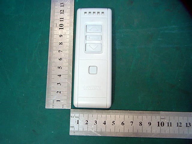
Click to zoom
Application Details
- Equipment Class
- DSR - Part 15 Remote Control/Security Device Transceiver
- Date of Grant
- Apr 24, 2007
- Application Purpose
- Original Equipment
- Date of Application
- Apr 24, 2007
- Equipment Note
- Electric Blind Remote
- Frequency Range
- 433.92000000 - 433.92000000
- Country
- China
Documents & Files
Document Text
Text extracted from the exhibit documents filed with the FCC. Open a document above to read the original.
Users Manual
1 YR1226 Remote Transmitter YR1226 remote control is used to control the motors. motors fit all kinds of electric roller blinds, canopies, Roman blinds, Venetian blinds, projection screens, awnings, and outside solar protections. This kind of motor integrated with a radio receiver within its casing, No wiring is required between the motor and its control point, and is compatible with low voltage switch. Specification Transmit modulate: 433.92MHz,ASK Transmit intensity: +10dBm Remote channel: 6 channels Battery: CR2032×1 Remote cradle holder: optional part Common buttons function: 1. YR1226 transmitter has six channels. Each light is one channel. Five lights flash at the same time means the sixth channel. [Channel choose] button can switch circularly any one channel. 2. [Up] [stop] [down] buttons separately transmit different function signals under the current selected channel. 3. [Channel setting] key is only used to set remote channels. Please see <setting methods>. 2 Group buttons function: 1. Group buttons will transmit function signals under the selected channel. 2. “[Stop] + [up]” means press [stop] key and do not release, then press [up] key one time”. 3. [Channel setting] + [stop]——transmit “exchange direction” signal. 4. [Channel setting] + [up]——transmit “speed up / slow-open” signal. 5. [Channel setting] + [down]——transmit “slow down / slow-open” signal. 6. [Stop] + [up]——transmit “startup IP1” signal. 7. [Stop] + [down]——transmit “startup IP2” signal. Attention: 1. Transmitter will return to the first channel automatically when without any operation within 25 seconds. This function will help consumer default the first channel every time. 2. YR1226 radio transmitter can compatible with different radio receivers. Different receivers will have different setting and use methods. The operation will base on the receiver’s manual. 3. Group buttons only fit for the receivers which has corresponding functions. Details please see receiver’s manual. Setting methods Before use, users must be set remote channel and sure that the transmit signals were recorded in the receiver. As soon as the controller receives remote signal, it will work. 3 If want to reset all the channels, please delete the remote channels firstly, then reset. When the work direction of the motor is different from the control direction, you needn’t change the cable connection. You can only correct the direction on the transmitter. Application Example YR1226 radio transmitter and AR8611 radio receiver setting steps: Setting remote channel 1. Press [Learning] key 3 seconds till the light is on, the controller enters into record state. 2. Press [channel choose] button on the transmitter, choose the needed channel. 3. Press [channel setting] key on the back of the transmitter. The channel will be recorded. Delete remote channel 1. Press [learning] key 3 seconds till the light is on. The controller enters into record state. 2. Re-press [learning] key 7 seconds till the light is off. Correct the direction 4 1. Press [learning] key 3 seconds till the light is on. The controller enters into record state. 3. Press [channel choose] button, do not release. Then press [Stop] button one time. FCC Information This device complies with Part 15 of the FCC rules. Operation is subject to the following two conditions: 1) this device may not cause harmful interference, and 2) this device must accept any interference received, including interference that may cause undesired operation. This equipment has been tested and found to comply with the limits for a Class B digital device, pursuant to Part 15 of the FCC rules. These limits are designed to provide reasonable protection against harmful interference in a residential installation. This equipment generates, uses and can radiate radio frequency energy and if not installed and used in accordance with the instructions, may cause harmful interference to radio communications. However, there is no guarantee that interference will not occur in a particular installation. If this equipment does cause harmful interference to radio or television reception, which can be determined by turning the equipment off and on, the user is encouraged to try correct the interference by one or more of the following measures: - Reorient the receiving antenna. - Increase the separation between the equipment and receiver. - Connect the equipment into and outlet on a circuit 5 different from that to which the receiver is connected. - Consult the dealer or an experienced radio/TV technician for help. Any special accessories needed for compliance must be specified in the instruction manual. Changes or modifications not expressly approved by the party responsible for compliance could void the user's authority to operate the equipment.
External Photos
External Photo 1 Photo 1 Appearance of EUT Photo 2 Appearance of EUT
ID Label/Location Info
FCC ID: U8NYR1226 YR1226 RF Remote 433.92MHz ASK FCC ID :U8NYR1226 This device complies with Part 15 o the FCC Rules. Operation is subject to the following two conditions: (1) this device may not cause harmful interference, and (2) this device must accept any interference received, including interference that may cause undesired operation. Label The Label must not be a stick-on paper label. The Label on these products must be permanently affixed to the product and readily visible at the time of purchase and must last the expected lifetime of the equipment not be readily detachable. Proposed Label Location on EUT FCC ID: FCCID :U8NYR1226 Label 3cm 6cm
Internal Photos
Internal Photo 1 Photo 1 Inside of EUT Photo 2 Inside of EUT Internal Photo 2 Photo 3 Inside of EUT
Operational Description
Y1226 operation description 1. Press the button, the MCU will wake up and start work. It will work according to the instruction of the button, including to turn on the LED light and transmit radio signal through ASK 433.9MHz. 2. When the pressing time of the button exceeds the initialization or the time of no pressing button signal exceeds the initialization, MCU will stop working and enter into a state of sleeping in order to reduce energy consumption.
Schematics
Title Number Revision Size A4 Date: 11-Apr-2007 Sheet of File: D:\GW-SE\ 瑞翔 .DD B Drawn By: YR1226 易建辉 R1 47K R7 1K RA1 18 RA0 17 OSC1 16 OSC2 15 GND 5 RB0 6 RB1 7 Vcc 14 RB7 13 RB6 12 RB2 8 RB3 9 RB5 11 RB4 10 RA2 1 RA3 2 TI 3 RST 4 U1EM78P156ELM R10 1K R9 1K R8 1K R510K LED5 LED1 LED2 LED3 LED4 R6 1K K2 K3 K4 K1 R2 47KR3 47KR4 47K Up Stop Down Channel Choose +3V +3V K5 Channel Setting R5 47K 4.00M 12 2032 BA X1550 Q3 YK R8 47K R9 470R L4 39N C910P C1015P C8 102P Q2YK R7 47K L1647NH C208P C4 15P C5102P Q1R25 R6 24K L1 27NH C2310P C25PC35P ANT L3 2U2 L2 2U2 +3V C22 102P C8104P C8102P
Test Report
Report No.: WT078000746 Page 1/25 EMC TEST REPORT For RF Remote Model Number: YR1226 YR2026 FCC ID: U8NYR1226 Report Number : WT078000746 Test Laboratory : Shenzhen Academy of Metrology and Quality Inspection EMC Laboratory Guangdong EMC Compliance Test Center Site Location : Bldg. of Metrology &Quality Inspection, Longzhu Road, Shenzhen, Guangdong, China Tel : 0086-755-26941637, 26941529, 26941531 Fax : 0086-755-26941545 Email : [email protected] Report No.: WT078000746 Page 2/25 TABLE OF CONTENTS TEST REPORT DECLARATION ........................................................................................................3 1. TEST RESULTS SUMMARY ...................................................................................................4 2. GENERAL INFORMATION ....................................................................................................5 2.1. Report information ............................................................................................................5 2.2. Laboratory Accreditation and Relationship to Customer .................................................5 2.3. Measurement Uncertainty .................................................................................................6 3. PRODUCT DESCRIPTION ......................................................................................................6 3.1. EUT Description ...............................................................................................................6 3.2. Related Submittal(s) / Grant (s) ........................................................................................6 3.3. Block Diagram of EUT Configuration..............................................................................6 3.4. Operating Condition of EUT ............................................................................................7 3.5. Special Accessories...........................................................................................................7 3.6. Equipment Modifications..................................................................................................7 3.7. Support Equipment List ....................................................................................................7 3.8. Test Conditions .................................................................................................................7 4. TEST EQUIPMENT USED .......................................................................................................8 4.1. Test Equipment Used to Measure Conducted Disturbance ..............................................8 4.2. Test Equipment Used to Measure Radiated Disturbance and bandwidth.........................8 5. CONDUCTED DISTURBANCE TEST ....................................................................................9 5.1. Test Standard and Limit ....................................................................................................9 5.2. Test Procedure ..................................................................................................................9 5.3. Test Arrangement..............................................................................................................9 5.4. Test Data ...........................................................................................................................9 6. RADIATED DISTURBANCE TEST ......................................................................................10 6.1. Test Standard and Limit ..................................................................................................10 6.2. Test Procedure ................................................................................................................10 6.3. Test Arrangement............................................................................................................11 6.4. Test Data .........................................................................................................................11 7. 20DB OCCUPIED BANDWIDTH ..........................................................................................14 7.1. Test Standard and Limit ..................................................................................................14 7.2. Test Procedure ................................................................................................................14 7.3. Test Arrangement............................................................................................................14 7.4. Test Data .........................................................................................................................14 8. SWITCH OFF TIME................................................................................................................16 8.1. Test Standard and Limit ..................................................................................................16 8.2. Test Procedure ................................................................................................................16 8.3. Test Data .........................................................................................................................16 9. ANTENNA REQUIREMENT .................................................................................................17 APPENDIX I TEST PHOTO...............................................................................................................18 APPENDIX II EUT PHOTO ...............................................................................................................22 Report No.: WT078000746 Page 3/25 TEST REPORT DECLARATION Applicant : Guangzhou Ruixiang Mechanical&Electronical Co.LTD Address : Qinglong Road,Qingfeng Industrial Park,shijing Baiyun,Guangzhou,china Manufacturer : Guangzhou Ruixiang Mechanical&Electronical Co.LTD Address : Qinglong Road,Qingfeng Industrial Park,shijing Baiyun,Guangzhou,china EUT Descript…
Text truncated - open the document above for the full version.
Test Setup Photos
Test Photo 1 Photo 1 Radiated Emission Test Photo 2 Radiated Emission Test Test Photo 2 Photo 3 Radiated Emission Test Photo 4 Radiated Emission Test Test Photo 3 Photo 5 Radiated Emission Test Photo 6 Radiated Emission Test
Contact Information
Applicant
jim Tan(manager)
Technical Contact
ShenZhen AcademyPeter Lin
[email protected]86-755-2694-1599
Bld. of Metrelogy, Longzhu Rd. · Nanshan, Shenzhen · China
Test Firm
Shenzhen Academy of Metrology & Quality InspectionPeter Lin
Technical Specifications
| # | Rule Parts | Frequency Range | Power Output |
|---|---|---|---|
| 1 | 15.231 | 433.92 MHz - 433.92 MHz | - |