Text extracted from the exhibit documents filed with the FCC. Open a document above to read the original.
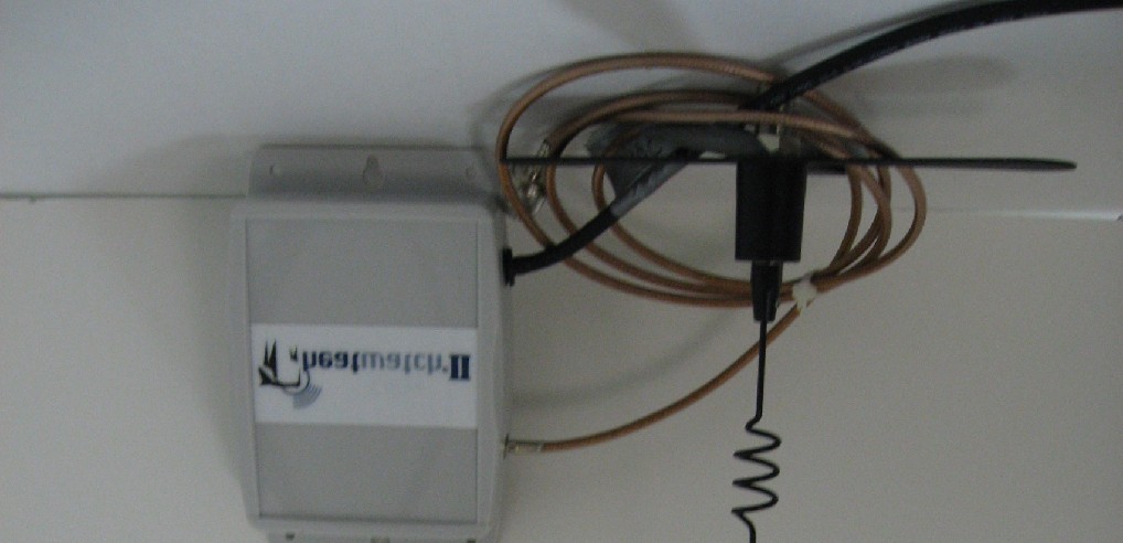
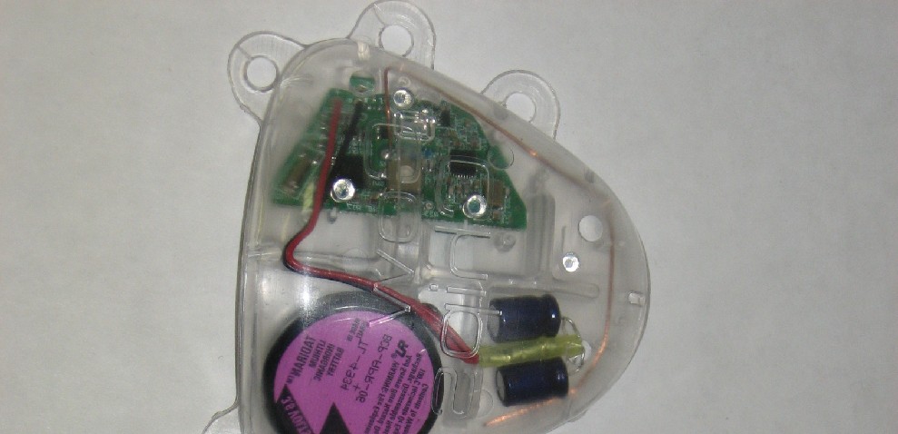
User’s Manual NOTICE The manufacturer reserves the right to make any changes and improvements in the product described in this manual at any time and without prior notice. This manual and the HeatWatch®II software are trademarked and copyrighted. All rights are reserved. This document may not, in whole or part, be copied, photocopied, reproduced, translated or reduced to any electronic medium or machine readable form without prior written consent from CowChips, LLC. Copyright © 2007 CowChips, LLC TRADEMARKS HeatWatch®II and HeatWatch® are registered trademarks of CowChips, LLC. All other trademarks are the property of their respective owners. PATENTS U.S. Patent 5,542,431 FCC APPROVAL This device complies with Part 15 of the FCC Rules. Operation is subject to the following two conditions: (1) this device may not cause harmful interference, and (2) this device must accept any interference received, including interference that may cause undesired operation. The user is cautioned that changes or modifications not expressly approved by the party responsible for compliance could void the user's authority to operate the equipment. FCC ID U8QHW2 - TAG FCC ID U8QHW2 - CM HEATWATCH II ESTRUS DETECTION SYSTEM HeatWatch II takes advantage of the fact that standing heat is the most accurate visible indicator for detecting cows and heifers in estrus. To monitor standing heat, HeatWatch uses a small radio frequency (RF) monitor and pressure sensor attached to the tailhead of the cow. The monitor sends information to a receiving/transmitting device called a base station each time a cow is mounted. The information is stored in the base station and is wirelessly transferred to another device called an access point which is connected to a computer by way of a USB port. The stored data is automatically uploaded to the computer when the HeatWatch II software is started. Using sophisticated algorithms developed over the past 10 years, the HeatWatch II software, running on a Windows based computer, analyzes the specific information received from each cow and gives accurate information for cows displaying mounting activity relating to estrus status and time to insemination. HEATWATCH II EQUIPMENT Monitors Monitors, the heart of the HeatWatch II system are small, transferable battery-powered digital radio frequency units containing a pressure sensor for detecting mounting activity and transmitting this data to the base station. The base station will send a return message to the monitor acknowledging its receipt of the data. If the monitor does not receive this acknowledgment message, it stores that mounting data and re-sends it on a periodic basis until the base station receives it. This would happen if a cow wanders out of range or is behind a obstacle that would prevent a signal from being received by the base station. Upon use, each monitor is enclosed in or attached on top of a patch that is glued to the tailhead of a cow. A monitor can transmit a mounting activity signal over a third of a mile in a line-of-sight to the base station or repeater. Transmission occurs multiple times on multiple frequencies over a 10 second period to ensure signal reception of mount data. Periodically, a supervisory signal is sent from the monitor as confirmation that the monitor is working properly. Should a monitor be in an active mode and not send a supervisory signal, as in the case of a dead battery, you will be alerted by the software. Each monitor has its own unique numerical identification code. No two monitors have the same ID. Monitor cases are constructed of hardened plastic designed to withstand mounting activity forces. The battery that powers the monitor is a 3.6 volt lithium battery. The device operates in a temperature range of -40 to +140 F. FCC site licensing is not required. Base Station The base station is a sophisticated electronic device that receives and stores mounting activity information from the cow monitors in the form of RF signals. The information is wirelessly transferred to the access point and into the HeatWatch II software. The base station also sends signals back to the monitors acknowledging the receipt of mounts and/or giving it certain instructions. The base station is encased in a weather-resistant enclosure and is positioned in a line of sight proximity to the cows. The maximum distance between the base station and the access point is a function of the types of antennas used on both devices. The standard configuration will allow for 1000 ft. The base station can be powered by either 110V outlet or 12V DC power. Access Point The access point receives mounting information from the base stations and passes that information to the computer. The access point is connected to the computer and powered by way of a high speed USB 2.0 cable. Patches and Glue A polyester patch has 3 functional components: 1. the base material used to affix the patch to the tailhead of the cow with Ruscoe glue. 2. the nylon pouch that encloses the monitor, and 3. the tail strap that can provide retention of the patch and monitor to the cow if the patch comes loose from intensive mounting. The Ruscoe glue is a contact-type cement that has been used in the cattle industry for years and is best known as Cattle Tag Cement. It is available in 10.5 oz caulking tubes. Repeater The repeater is a sophisticated transceiver which identifies signals from HeatWatch II monitors and re-broadcasts those signals at full power. The repeater is used to relay mounting information to the base station on large farms and ranches, or from area with hidden mounting or heat detection locations. This effectively increases the range by several miles in line-of-sight to the base station. HOW HEATWATCH II WORKS 1. HeatWatch II is a reproductive management tool. When a cow is mounted, the pressure sensor in the monitor on the tailhead of the cow is activated. Mount data are transmitted the base station in multiple signals following a mount. The bas…
Text truncated - open the document above for the full version.
CowChips, LLC FCC ID: U8QHW2-TAGPage 1 of 14 Product Safety Engineering, Inc 12955 Bellamy Brothers Blvd. Dade City, FL 33525 352-588-2209 TEST REPORT 07F101 08/02/2007 Applicant: CowChips, LLC 24 Iron Ore Rd Manalapan, NJ 07726 Product: Model - Cowtag FHSS Transceiver In Accordance with FCC Part 15.247 Test dates: 02/12/2007 - 02/17/2007 Receive Date: 02/12/2007 Prepared by: Steven E. Hoke - EMC Site Manager This report may only be reproduced in full without written permission from Product Safety Engineering, Inc. Testing Certification # 1367-01 CowChips, LLC FCC ID: U8QHW2-TAGPage 2 of 14 Table of Contents Table of contentsPage 2 Test proceduresPage 3-4 Test SummaryPage 5 Peak Output Power Test DataPage 6 Powerline Conducted EmissionsPage 7 20 dB BandwidthPage 8 Channel SeparationPage 9 Number of Hopping FrequenciesPage 10 Dwell TimePage 11 Spurious Emissions & Restricted Band CompliancePage 12 RF ExposurePage 13 Antenna SpecificationsPage 14 Exhibit 1 - Powerline Conducted Emissions Page 15 Exhibit 2 - Bandwidth PlotsPage 16 Exhibit 3 - Channel SeparationPage 17 Exhibit 4 - Number of Hopping FrequenciesPage 18 Exhibit 5 - Dwell TimePage 19 - 20 Exhibit 6 - Output Power & Spurious EmissionsPage 21 Exhibit 7 - Antenna InformationN/A CowChips, LLCFCC ID: U8QHW2-TAGPage 3 of 14 Test Procedures Product description: The system utilizes FHSS type transmitters. The Cowchips HWII system is comprised of 4 different RF devices. The first device is the Cow Tag. It is a simple transceiver responsible for monitoring the activities of the cow. The other 3 devices are based on the same hardware platform with build and software variations. They are the Access Point, Base Station, and Repeater. They are collectively referred Common Module. Powerline conducted interference: The AC powerline conducted emissions measurements were not applicable due to battery operation. 20 dB Bandwidth: The EUT had its hopping function disabled while modulated. The spectrum analyzer span was set to (2-3) times the (20) dB bandwidth. The spectrum analyzer was placed in peak hold mode and the upper and lower points of the waveform were measured at a level that was (20) dB down from the peak amplitude. This was repeated for a low, mid and high frequency channel. Channel Separation: The EUT had its hopping function enabled. The span on the spectrum analyzer was set wide enough to capture at least (2) adjacnet channels. The channel separation was determined by measuring the peak frequency of (2) adjacent channels. Description of frequency hopping system: The system utilizes 25 channels from 904.296 MHz to 926.250 MHz in the ISM band. The RF Unit hops though each of these channels at a rate of 375ms per channel, for a total hopping loop of 9.375 seconds. The system initiates data transmissions completely asynchronously from the hopping system which creates a random distribution of data for each channel. All messages are also acknowledged, which provides significant bandwidth throttling (i.e. messages can not be sent continuously) which limits duty cycle per transmitter about 50%. Due to system limitations such as a maximum payload size of 32bytes, 5khz bit rate, and a fixed 7 bytes packet overhead, the longest time a RF transmitter can be active is 78ms. All channels are used all of the time. There are not any facilities to detect jammed or undesirable channels and remove them from the hopping system. Receiver bandwidth: The system receivers shall have input bandwidths that match the hopping channel bandwidths of their corresponding transmitters and shall shift frequencies in synchronization with the transmitted signals. Number of hopping frequencies: With the spectrum analyzer in peak hold, we stored an image of all the channels operating and then produced a plot of the analyzer. We manually counted each channel to determine the number. Dwell time: The EUT had its hopping function enabled. The average time of occupancy was first determined by measuring the width of a single channel with the spectrum analyzer in a zero span mode and then with the analyzer in a peak hold mode, a (10) second sweep was then performed to determine how many single channels occupied a (10) second period of time. CowChips, LLCFCC ID: U8QHW2-TAGPage 4 of 14 RF Exposure Compliance Requirements: Systems operating under the provisions of this section shall be operated in a manner that ensures that the public is not exposed to radio frequency energy levels in excess of the Commission’s guidelines. Computations included in test report. Peak output power: The EUT has an integrated antenna that prohibited direct connection to the measuring equipment. We performed radiated field strength measurements as an alternative test procedure as defined in FCC DA 00-705. Conducted output power: Not applicable for integrated antenna. Operation with directional antenna gains greater than 6 dBi: Not applicable for integrated antenna. Spurious emissions: All spurious emissions were measured up to the tenth harmonic per ANSI C63.4:2003. Restricted Band Compliance: All emissions were measured per ANSI C63.4:2003 and compared to the restricted band list. CowChips, LLCFCC ID: U8QHW2-TAGPage 5 of 14 Test Summary Name of TestParagraph No.SpecificationMeasurementResult Powerline Conducted Emissions 15.207(a)Table 15.207(a)N/AComplies Channel Separation15.247(a)(1)Greater of 25 kHz or 20 dB bandwidth 928 kHzComplies Pseudo-random Hopping Algorithm 15.247(a)(1)Complies Hopping Frequencies15.247(a)(1)(i)at least 2525Complies Dwell Time15.247(a)(1)(ii)<0.4 sec in 10 sec0.0302 sec in 10 sec Complies 20 dB Occupied Bandwidth 15.247(a)(1)>250 kHz <500 kHz268-294 kHzComplies Peak Output Power15.247(b)0.25 Watts0.0134 WattsComplies Spurious Emissions (Conducted / Radiated) 15.247(d)-20 dBc (peak) -30 dBc (avg) -59.5 dBcComplies Spurious Emissions (Radiated) 15.247(d)54.0 dBuV/m per Table 15.209(a) 43.6 dBuV/mComplies CowChips, LLC FCC ID:U8QHW2-TAGPage 6 of 14 Test: Output Power per 15.247…
Text truncated - open the document above for the full version.
| # | Rule Parts | Frequency Range | Power Output |
|---|---|---|---|
| 1 | 15C | 904.29 MHz - 926.25 MHz | 13.40 mW |

SPREAD SPECTRUM TRANSCEIVER
Equipment Class
DSS - Part 15 Spread Spectrum Transmitter