U8UGC762981POOL ALARM
SafeBlue SA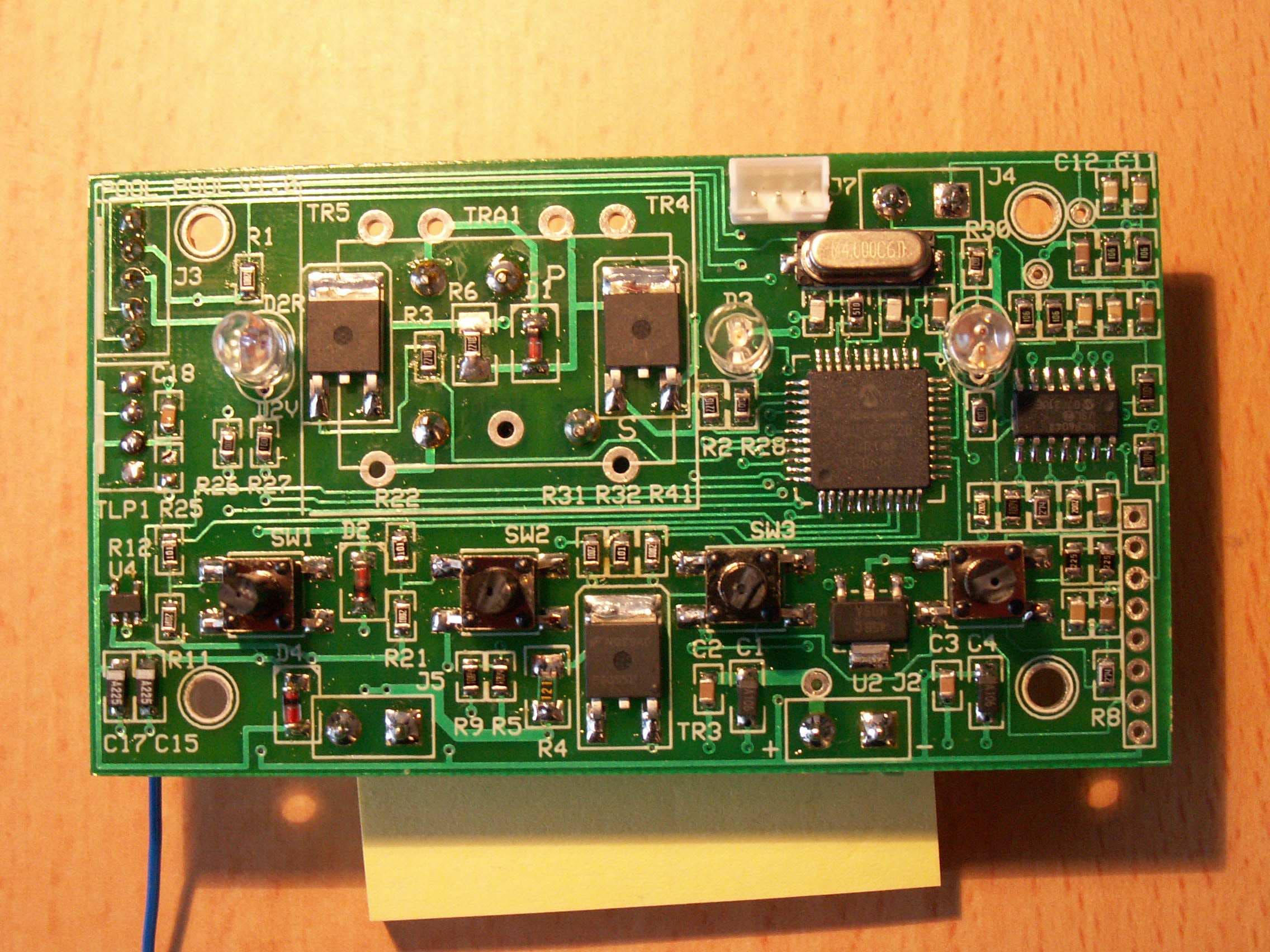
Click to zoom
Application Details
- Equipment Class
- DSC - Part 15 Security/Remote Control Transmitter
- Date of Grant
- Apr 30, 2007
- Application Purpose
- Original Equipment
- Date of Application
- Apr 30, 2007
- Equipment Note
- POOL ALARM
- Frequency Range
- 433.92000000 - 433.92000000
- Company
- SafeBlue SA
- Country
- Switzerland
Documents & Files
Document Text
Text extracted from the exhibit documents filed with the FCC. Open a document above to read the original.
Users Manual
Installation and user guide- 1 TRITON™ Pool Alarm: TRIT001-US INSTALLATION GUIDE AND USER MANUAL T O READ CAREFULLY AND TO KEEP FOR LATER LOOK UP SYNOPSIS 1 Introduction – Important Safety Precautions............................................................................................. 2 2 Checking the package.................................................................................................................................... 3 3 Quick Start Guide.......................................................................................................................................... 4 4 Operating principle........................................................................................................................................ 5 5 TRITON™ installation.................................................................................................................................. 9 5.1 Placing the Batteries ............................................................................................................................... 10 5.2 Location choice....................................................................................................................................... 10 5.3 Temporary installation ............................................................................................................................ 11 5.4 Installation Tests ..................................................................................................................................... 11 5.5 Final installation ..................................................................................................................................... 12 6 Recommendations for remote siren installation........................................................................................ 13 7 TRITON™ Operating principle................................................................................................................. 15 7.1 I want to swim ........................................................................................................................................ 15 7.2 Automatic reset ....................................................................................................................................... 16 7.3 Manual reset............................................................................................................................................ 16 7.4 Too much wind ....................................................................................................................................... 16 7.5 Attenuated siren mode ............................................................................................................................ 17 7.6 Password Change mode .......................................................................................................................... 17 7.7 OFF mode ............................................................................................................................................... 17 7.8 Replacing the batteries............................................................................................................................ 18 7.9 I have an issue with my falling detector ................................................................................................. 18 8 FAQ Frequently asked questions................................................................................................................ 20 9 Warranty and after sale services................................................................................................................ 23 10 Monthly Tests............................................................................................................................................... 24 FCC REGULATION This device complies with part 15 of the FCC Rules. Operation is subject to the following conditions: (1) This device may not cause harmful interference, and (2) This device must accept any interference received, including interference that may cause undesired operation. Per FCC Part 15.21, any changes or modification not expressly approved by ABTYS could void the user's authority to operate the equipment. Note: the manufacturer is not responsible for any radio or TV interference caused by unauthorized modifications to this equipment. Such modifications could void the user’s authority to operate the equipment. FALL DETECTOR FOR SWIMMING POOL TRITON™ Pool Alarm Installation and user guide- 2 1 Introduction – Important Safety Precautions You just bought a swimming pool alarm TRITON™ and we would like to thank you for choosing our products and service. This alarm meets requirements of ASTM standard F2208e1. This user guide will allow you to install your swimming pool alarm and understand the way it works. If you have any comments or questions, please feel free to contact your reseller, write or call us at the address below: TRITON™ Pool Alarm Customer Care SafeBlue c/o Gestrust, 2 rue Thalberg Case postale 1507 1211 Geneve 1 - Switzerland • TRITON™ is a subsurface pool device which detects the fall of an 18+ lbs child by providing automatically sounding an alarm. • This device is not intended to replace any other safety consideration; that is, adult supervision, lifeguards, fences, gates, pool covers, locks, and so forth, and some devices may not detect gradual entry. • TRITON™ isn’t a rescue device: The intervention of a responsible grown-up is mandatory while the alarm rings out. • Under no circumstances, your re-seller or the swimming pool alarm producer shall be liable and assume responsibility for fall or drowning of an animal or a person. • Please warn all the users that the pool and its access are under electronic supervision. Please read carefully the safety information through out this user manual and specifically on page xxx of this manual. Installation and user guide- 3 2 Che…
Text truncated - open the document above for the full version.
Block Diagram
Quartz 4Mhz μProcessor Alim RF (regulator 2.0V) RF Emitter (Laipac) 433Mhz 4 x 1.5V Batteries Alim regulator ( 3.3V) Signal Processing Pressure Sensor Siren DC/AC Power Converter User Interface (leds, buttons) Mother board Mezzanine board Triton poolalarm
External Photos
This device complies with part 15 of the FCC Rules. Operation is subject to the following two condition s: 1.This device may not cause harmful interference, a nd 2.This device must accept any interference received , including interference that may cause undesired ope ration. TRITONPOOLALARM #: AASSHHPNNNNNN FCCID: U8UGC762981 2007 30mm 70mm
ID Label/Location Info
TPA Project Version : 1.00 Date : 24/04/07 Page : 1/5 CONFIDENTIEL - Ce document ne peut être copié ou reproduit sans autorisation TRITON Pool Alarm OpDes.doc OPERATIONAL DESCRIPTION OF TRITON™ POOL ALARM RF PART ONLY Affaire : PROJET TPA TPA Project Version : 1.00 Date : 24/04/07 Page : 2/5 CONFIDENTIEL - Ce document ne peut être copié ou reproduit sans autorisation TRITON Pool Alarm OpDes.doc Reference TPA_Intended_uses_V100_220407_RF_Only.doc Date : 24/04/07 Rédigé par : Damien PLUTINO Philippe Crahay Approuvé par : Historical Version Status/Date (draft/invalide/valide) (dd-mmm-yyyy) Author Control Description 1.00 24/04/07 Valid Damien PLUTINO Philippe CRAHAY Extraction from definition file.v1.02 TPA Project Version : 1.00 Date : 24/04/07 Page : 3/5 CONFIDENTIEL - Ce document ne peut être copié ou reproduit sans autorisation TRITON Pool Alarm OpDes.doc SYNOPSIS 1. RADIO FREQUENCIES DETAILS 4 1.1 P ARAMETERS DEFINITION: 4 1.2 TRANSMISSION DEFINITION 4 1.3 WORST CASE OF EMISSION PERCENTAGE IN A 100MS WINDOW 5 TPA Project Version : 1.00 Date : 24/04/07 Page : 4/5 CONFIDENTIEL - Ce document ne peut être copié ou reproduit sans autorisation TRITON Pool Alarm OpDes.doc 1. Radio Frequencies Details 1.1 Parameters definition: -Radio frequency: 433.92 MHz -Bit_Time = 380 μs +/- 10%, Signal bit length -Interframe_Time = 15 ms +/- 10%, Time between frame -NB_Frame = 5, number of frame by message -CODE_STOPLEARN = 00001100, Code acquisition and siren stop -CODE_ALERT = 00110000, Siren Trigger -WARN_PERIOD = 3s, Time between message for warning signal (See diagrams below) 1.2 Transmission definition The device transmits messages by Radio Frequency data. These messages include NB_Frames (5) RF frames. Between the frames, there’s a time without signal emission of Interframe_time (15ms). Frame 1Frame 2Frame 3 Interframe_Time 5 Frames message Frame 4Frame 5Frame 1Frame 2Frame 3 Interframe_Time 5 Frames message Frame 4Frame 5 Each frame is coded on 3 bytes plus 1 bit. The frame definition is: RF_STOP_LEARN = ID1 / ID2 / CODE_STOPLEARN / 0 RF_ALERT = ID1 / ID2 / CODE_ALERT / 0 In case of warning signals, the 5 frames serie is sent every 3s during the whole triggering time. ID1 = 1 identifying byte which value is 1100000 ID2 = 1 identifying byte which value is a random number with one “1” at random place, and “0” elsewhere. TPA Project Version : 1.00 Date : 24/04/07 Page : 5/5 CONFIDENTIEL - Ce document ne peut être copié ou reproduit sans autorisation TRITON Pool Alarm OpDes.doc The position of the “1” is set by a random number between 0 and 7, obtained by reading the 3 lower bits of a timer value without taking care about when this timer started. The logical values of the above bits are coded in the signal with this formalism: Once Bit_Time of signal followed by 3 times Bit_time without signal = 0. Three times Bit_Time of signal followed by 1 time Bit_Time without signal =1. 1.3 Worst case of emission percentage in a 100ms window We can consider that the worst duration case for the emission in a window of 100ms is when this window contains 2 complete frames, 1 complete inter frame and one partial inter frame. In a frame, the biggest number of one in the data is 10 on 25 bits of data. So the worst frame has an emission time of 5 * 3 Bit_Time + 20 * 1 Bit_Time = 35 Bit_Time = 13.3ms For 2 frames, we have an emission time of 2 * 13.3 = 26.6ms. So, the emission percentage in a window of 100ms, in the worst case, is theoretically 26.6%. To pay attention about variations of characteristics of the product, we’ll use a percentage of 28%.
Operational Description
TPA Project Version : 1.00 Date : 24/04/07 Page : 1/5 CONFIDENTIEL - Ce document ne peut être copié ou reproduit sans autorisation TRITON Pool Alarm OpDes.doc OPERATIONAL DESCRIPTION OF TRITON™ POOL ALARM RF PART ONLY Affaire : PROJET TPA TPA Project Version : 1.00 Date : 24/04/07 Page : 2/5 CONFIDENTIEL - Ce document ne peut être copié ou reproduit sans autorisation TRITON Pool Alarm OpDes.doc Reference TPA_Intended_uses_V100_220407_RF_Only.doc Date : 24/04/07 Rédigé par : Damien PLUTINO Philippe Crahay Approuvé par : Historical Version Status/Date (draft/invalide/valide) (dd-mmm-yyyy) Author Control Description 1.00 24/04/07 Valid Damien PLUTINO Philippe CRAHAY Extraction from definition file.v1.02 TPA Project Version : 1.00 Date : 24/04/07 Page : 3/5 CONFIDENTIEL - Ce document ne peut être copié ou reproduit sans autorisation TRITON Pool Alarm OpDes.doc SYNOPSIS 1. RADIO FREQUENCIES DETAILS 4 1.1 P ARAMETERS DEFINITION: 4 1.2 TRANSMISSION DEFINITION 4 1.3 WORST CASE OF EMISSION PERCENTAGE IN A 100MS WINDOW 5 TPA Project Version : 1.00 Date : 24/04/07 Page : 4/5 CONFIDENTIEL - Ce document ne peut être copié ou reproduit sans autorisation TRITON Pool Alarm OpDes.doc 1. Radio Frequencies Details 1.1 Parameters definition: -Radio frequency: 433.92 MHz -Bit_Time = 380 μs +/- 10%, Signal bit length -Interframe_Time = 15 ms +/- 10%, Time between frame -NB_Frame = 5, number of frame by message -CODE_STOPLEARN = 00001100, Code acquisition and siren stop -CODE_ALERT = 00110000, Siren Trigger -WARN_PERIOD = 3s, Time between message for warning signal (See diagrams below) 1.2 Transmission definition The device transmits messages by Radio Frequency data. These messages include NB_Frames (5) RF frames. Between the frames, there’s a time without signal emission of Interframe_time (15ms). Frame 1Frame 2Frame 3 Interframe_Time 5 Frames message Frame 4Frame 5Frame 1Frame 2Frame 3 Interframe_Time 5 Frames message Frame 4Frame 5 Each frame is coded on 3 bytes plus 1 bit. The frame definition is: RF_STOP_LEARN = ID1 / ID2 / CODE_STOPLEARN / 0 RF_ALERT = ID1 / ID2 / CODE_ALERT / 0 In case of warning signals, the 5 frames serie is sent every 3s during the whole triggering time. ID1 = 1 identifying byte which value is 1100000 ID2 = 1 identifying byte which value is a random number with one “1” at random place, and “0” elsewhere. TPA Project Version : 1.00 Date : 24/04/07 Page : 5/5 CONFIDENTIEL - Ce document ne peut être copié ou reproduit sans autorisation TRITON Pool Alarm OpDes.doc The position of the “1” is set by a random number between 0 and 7, obtained by reading the 3 lower bits of a timer value without taking care about when this timer started. The logical values of the above bits are coded in the signal with this formalism: Once Bit_Time of signal followed by 3 times Bit_time without signal = 0. Three times Bit_Time of signal followed by 1 time Bit_Time without signal =1. 1.3 Worst case of emission percentage in a 100ms window We can consider that the worst duration case for the emission in a window of 100ms is when this window contains 2 complete frames, 1 complete inter frame and one partial inter frame. In a frame, the biggest number of one in the data is 10 on 25 bits of data. So the worst frame has an emission time of 5 * 3 Bit_Time + 20 * 1 Bit_Time = 35 Bit_Time = 13.3ms For 2 frames, we have an emission time of 2 * 13.3 = 26.6ms. So, the emission percentage in a window of 100ms, in the worst case, is theoretically 26.6%. To pay attention about variations of characteristics of the product, we’ll use a percentage of 28%.
Parts List/Tune Up Info
Manufacturer: Plant Location: Model Number: Part Description/Number Pool's edge PCB / V1 Microprocessor/ 18F4520 Radio transmitter/ TLP434A Siren / KPEG1600NC Power transformer Pressure sensor / SMAT 13 MC SP04 P10 Sensor PCB Case base / POOL POOL BOTTOM 230207.x_t Case cover / POOL POOL TOP 230207.x_t Bulged cap (screw cap) / POOL POOL BULGED CAP 230207.x_t Sensor support / POOL POOL SINGLE SENSOR HOLDER SCS 17 230207.x_t Hard pipe int. Ø 25mm, 1mm thick Soft pipe int. Ø 12mm, 1.5mm thick Front panel Batteries / LR 20 Battery strap holder / ONE-WRAP® Fasteners, max. 20mm wide PCB screw (binding head self-tapping screw) / A2 2.6x6.5mm Battery holder screw (binding head self-tapping screw) / A2 2.6x6.5mm Pipe screw (binding head self-tapping screw) / A2 2.6x6.5mm Leakage / purge screw (binding head self-tapping screw) / A2 2.6x6.5mm Sensor holder screw (binding head self-tapping screw) / A2 2.6x8mm Case tapping screw (binding head machine screw) / A4 M4x30mm Case tapping insert / M4x9.5mm Fixing screw case (binding head tapping screw) / A4 8x45mm Case sud ext. Ø 22 mm, int. Ø 7mm, 10mm thick, density 140kg/m3 Fixing plug 8*40mm 2 washers: 1 steel/zinc, 1 nylon; M5x20mm Glue Siren seal O-ring, int. Ø 47.29mm, 2.62mm thick Case seal 1~1.5mm thick Sensor seal - gasket / JOINT DE CAPTEUR.DXF Paper box Accessories bag Alarm logo company label Alarm regulation label Electrical board serial number sticker Box label F2208-02e1 Certificate FCC Certificate User manual End Use: Subsurface swimming pool alarm Temperature of Exposure : Fabricator Wetted Contact Area in2 Material Type including Metal Alloy K2G/MIGHT0 Plastic Microchip0 silicium LAYPAC0 PCB+ inox Kingstate0 Plastic Myrra/Kingstate0 Plastic / metal Sonitron0 Plastic K2G/MIGHT0 Plastic Geenlong0 ASA Geenlong0 ASA Geenlong0 ASA Geenlong0 ASA Geenlong41.77 PVC Yao Wei51.14 PVC or PE Honlex0 Polycarbonate Duracell0 VELCRO© 0 Inox Lian Her/?0 Inox Lian Her/?0 Inox Lian Her/?0 Inox Lian Her/?0 Inox Lian Her/?0 Inox Lian Her/?0 Inox Lian Her/?0 Plastic Lian Her/?0 Inox Everwang0 EPDM 0 Nylon Lian Her/?0 Nylon - Steel/zinc 0 Cyanolit Yao Wei0 Silicon Yao Wei0 Silicon Everwang0 EPE Yi Chang0 Paper 0 Plastic CILS0Polycarbonate CILS0 Polycarbonate CILS0Polycarbonate CILS0 Polycarbonate 0Paper 0 Paper 0Paper Pool End Use _X_ _20_° °° ° __C_ (F or C) TRITON Pool Alarm PARTS LIST SafeBlue Taiwan TRIT001 - US Material SupplierFormulation ID NumberColor Policy Number NSF Standard Reference MFCR DCC# Green black Green / Inox Red / White Red Grey Green ChimeiWhite ChimeiWhite ChimeiWhite ChimeiWhite ChimeiWhite Clear white White / clear Gold/ Black Inox Inox Inox Inox Inox Inox Inox Grey Inox White White White Clear Black Black Brown Clear Pool and Spa End Use_____
Schematics
\\Altior333\tpa\HARDWARE\le nouveau v 1.0\Pool_Pool _V1_0.sch - Sheet1
Test Report
R041-07-100329-1A - RG / CD RADIO TEST REPORT According to the standard(s): FCC part 15 (02/2006) Equipment under test: Detector of immersion for swimming-pool TRITON Pool Alarm FCC ID: U8UGC762981 Company: SAFEBLUE SA Diffusion: Mr FONZES (Company: ALTRAN) Number of pages: 19 including 4 annexes Ed. Date Modified page(s) Written by Name Visa Technical verification Name Visa Quality approval Name Visa 0 27-Apr-07 Creation Régis GONZALEZ Olivier HEYER Olivier HEYER Duplication of this report is only permitted for an integral photographic facsimile. It includes the number of pages referenced above. This document is the result of testing a specimen or a sample of the product submitted. It does not imply an assessment of the conformity of the whole production of the item tested. R041-07-100329-1A Ed.0 PAGE: 2 NAME OF THE EQUIPMENT UNDER TEST (E.U.T.) : Detector of immersion for swimming-pool TRITON Pool Alarm Serial number : PCB # 3 and # 22 Part number : None Software Version : None MANUFACTURER'S NAME : ALTRAN APPLICANT’S ADRESS: Company : SAFEBLUE SA Adress : C/o Gestrust 2 rue Thalberg Case Postale 1507 GENEVE 1 SWITZERLAND Person(s) present during the tests : Mr CRAHAY Responsible : Mr FONZES DATE(S) OF TESTS : April, the 5 th and the 19 th of 2007 TESTS LOCATION(S) : EMITECH Grand Sud laboratory in Vendargues (34) Open area test site in Salinelles (30) FCC Registration Number: 812719 TESTS SUPERVISOR(S) : None TESTS OPERATOR(S) : Régis GONZALEZ R041-07-100329-1A Ed.0 PAGE: 3 CONTENTS 1. INTRODUCTION................................................................................................................................4 2. REFERENCE DOCUMENT(S)...........................................................................................................4 3. EQUIPMENT UNDER TEST CONFIGURATION ...............................................................................4 4. EQUIPMENT CHARACTERISTIC .....................................................................................................5 5. EQUIPMENT UNDER TEST CONFIGURATION SCHEME ...............................................................5 6. SUMMARY OF TEST RESULTS .......................................................................................................6 7. RADIATED ELECTRIC FIELD MEASUREMENT..............................................................................7 ANNEX 1: PHOTOGRAPH(S) ...................................................................................................................9 ANNEX 2: EMISSION BANDWIDTH........................................................................................................14 ANNEX 3: TRANSMISSION BURST........................................................................................................16 ANNEX 4: MANUALLY OPERATED TRANSMISSION DURATION .......................................................18 R041-07-100329-1A Ed.0 PAGE: 4 1. INTRODUCTION This document submits the results of Radio tests performed on the equipment Detector of immersion for swimming-pool TRITON Pool Alarm (denominated hereafter E.U.T.: equipment under test) according to document(s) listed below. 2. REFERENCE DOCUMENT(S) FCC Part 15 (02/2006) Code of Federal Regulations Title 47 – Telecommunications Chapter 1 – Federal Communications Commision Part 15 – Radio frequency devices Subpart C – Intentional Radiators ANSI C 63.4 (03) American National Standard for Methods of measurement of Radio-Noise from low-voltage Electrical and Electronic Equipment in the Range of 9 kHz to 40 GHz 3. EQUIPMENT UNDER TEST CONFIGURATION Equipment under test (E.U.T.) general description : Stand alone detector of immersion for swimming-pool Equipment control procedure during immunity tests : N.A. emission test only Susceptibility criteria during a continuous disturbance : N.A. emission test only Susceptibility criteria during a transitory disturbance : N.A. emission test only Cycle and operating mode during emission tests : Permanent no modulated emission exepted for bandwidth measurement Equipment modifications applied during tests : No N.A.: Not applicable R041-07-100329-1A Ed.0 PAGE: 5 4. EQUIPMENT CHARACTERISTIC FCC ID: U8UGC762981 ITU emission code: 4K75A1D Utilization: Swimming-pool alarm system Antenna type: Integrated wire antenna Operating frequency: 433.92 MHz Number of channels: 1 Channel spacing: Not concerned Frequency generation: □ SAW Resonator ⌧ Crystal □Synthetizer Modulation: ⌧ Amplitude (pulsed modulated device) □ Digital □ Frequency □ Phase Power source: 4 x LR20 alkaline cells (4 x 1,5 V = 6 V) 5. EQUIPMENT UNDER TEST CONFIGURATION SCHEME Equipment is set out on a wooden table at 0.8 m of the ground plane (see Photographs) in annex 1). R041-07-100329-1A Ed.0 PAGE: 6 6. SUMMARY OF TEST RESULTS Tests designation or section Results satisfying? Comments 15.33 Frequency range of radiated measurement - Considered 15.35 Measurement detector functions and bandwidths - Considered 15.203 Antenna requirement YES Nota 1 15.205 Restricted bands of operation YES 15.209 Radiated emission limits, general requirements YES Considered 15.231 Periodic operation in the band 40.66 – 40.70 MHz and above 70 MHz a) Transmission requirements YES Nota 2 b) Radiated emission YES Nota 3 c) Occupied bandwidth YES Nota 4 d) Frequency tolerance N.A. E.U.T. does not transmit in the band 40.60 – 40.70 MHz e) Periodic alternate field strength measurement N.A. Requirements of a) is used N.P.: Not Performed. N.A.: Not Applicable. Sample submitted to the tests complies with the regulations of the standard FCC part 15 (02/2006) according to limits specified in this tests report. Nota 1: Internal antenna without connector Nota 2: Periodic transmissions at regular predetermined intervals are not used. When manually operated transmission is used (switch on / off), the duration is less than 5s (see photographs in annex 4) When E.U.T. transmits an alarm, it operates during the pendency of the alarm co…
Text truncated - open the document above for the full version.
Contact Information
Applicant
Marc ANGST
Test Firm
EMITECH Grand SudOlivier Heyer
Technical Specifications
| # | Rule Parts | Frequency Range | Power Output |
|---|---|---|---|
| 1 | 15.231 | 433.92 MHz - 433.92 MHz | - |