U8YWMT-001Wander Monitor
1227884 Alberta Ltd.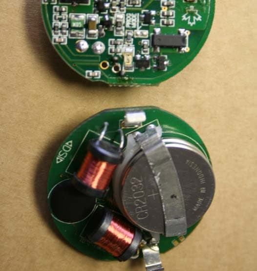
Click to zoom
Application Details
- Equipment Class
- DSR - Part 15 Remote Control/Security Device Transceiver
- Date of Grant
- Jul 29, 2007
- Application Purpose
- Original Equipment
- Date of Application
- Jul 29, 2007
- Equipment Note
- Wander Monitor
- Frequency Range
- 315.00000000 - 315.00000000
- Company
- 1227884 Alberta Ltd.
- Country
- Canada
Documents & Files
Document Text
Text extracted from the exhibit documents filed with the FCC. Open a document above to read the original.
Users Manual
. . . . . . . . . . .......... WanderCOMM WPS WPSWPS WPS “Wander Protection System” by DS Integrations Inc. We mark the next generation for Residents and Staff in Health Care Security TODAY. WanderCOMM 2 DS Integrations Inc. #202 9074 51 Avenue Edmonton, Alberta Canada T6E 5X4 Telephone: 1-800-661-6173 or 1-780-463-9490 Facsimile: 1-780-463-6074 Web site: www.dsintegrations.com © 2000 - 2007 DS Integrations Inc. All Rights Reserved. WanderComm and VoiceComm are trademarks of DS Integrations Inc. in North America. Other brand and product names are trademarks or registered trademarks of their respective holders. Printed in Canada. WPS-Manual Rev 3.2 April 2005. WanderCOMM 3 Limitation of Liability This Product has been designed for use to reduce the risk of resident wandering through remote detection. The range, accuracy, function and performance of this Product may vary from the published specifications due to many factors, including, without limitation, site impairments from structural effects, metal objects in the vicinity, placement of the receiver and transmitter, interference from other electrical devices, atmospheric effects, installation, and maintenance. Other factors may also affect performance of this Product. DSI does not guarantee that this Product will detect 100% of resident wanderings. DSI does not guarantee that this Product will not return false reports of resident wandering. Weekly testing of this Product, as described in the Product documentation, is essential to verify the system is operating correctly and to ensure that the probability of detecting an alarm and/or locating the transmitter is maximized. The failure to undertake regular testing will increase the risk of system failure and failure to detect resident wandering. The failure to undertake regular testing will increase the risk of false reports of resident wandering. DSI hereby disclaims all warranties, express or implied, arising out of or in connection with any of its Products or the use or performance thereof, including but not limited to, where allowable by law, all other implied warranties or conditions of merchantable quality and fitness for a particular purpose and those arising by statute or otherwise in law or from a course of dealing or usage of trade. DSI’s liability to you or anyone claiming through or on behalf of you with respect to any claim or loss arising out of the use or misuse of DSI’s Product, defective products or materials, improper installation or maintenance of DSI’s Product or products or the system in which they are incorporated, or alleged to have resulted from an act or omission of DSI or any person, negligent or otherwise, shall be limited to: A) the repair or replacement of defective Product or materials supplied by DSI during the warranty period as set out in the Product documentation; or, at the option of DSI, B) refund of the purchase price of the Product supplied by DSI. In no event shall DSI be liable for general, specific, indirect, consequential, incidental, exemplary, or punitive damages or any losses or expenses suffered by you or anyone else, whether or not DSI, its employees, officers, agents, resellers, or installers have been informed of the risk of such loss or expense and whether or not such losses or expenses were foreseeable. WanderCOMM 4 Contents 1.0 Introduction 6 1.1 Overview of the Wander Protection System 7 1.2 Terminology 7 2.0 Installation of the Wander Monitor Loop Generator 8 2.1 WML general Description 9 2.2 Location 9 2.3 Terminal Wiring 9 2.4 Installation of loop wire 10 2.5 Splicing wire 10 2.6 Burying the wire 10 3.0 Installation of the Wander Monitor Controller 11 3.1 WMC general description 12 3.2 Dip switch settings 13 3.3 Input circuits 13 3.4 Output circuits 14 3.5 LEDs 15 3.6 Speaker messages 15 3.7 Reporting modes and levels of operation 16 3.7.1 Level 1 – Wanderer 16 3.7.2 Level 2 – Resident 16 3.7.3 Level 3 – Staff 16 3.8 Environmental modes 17 3.9 Tamper event reporting 17 3.10 Spider installation__________________________________________ 18 4.0 Installation of the Wander Monitor Transmitter 18 4.1 WMT general description 19 4.2 Programming Area description 19 4.3 Transmitter programming 21 4.4 Bracelet assembly 22 5.0 Appendix 23 5.1 Specifications 24 5.2 Warranty information 24 5.3 Applications 25 5.4 Wiring Planner 31 5.5 Notes 32 WanderCOMM 5 Section Introduction This manual provides instructions to install, configure, and test the Wander Protection System. For operating instructions, please see the Wander Protection System End-User Guide. The Wander Protection System is configurable to meet the specific needs of the facility. Some common system configurations and applications are covered in this manual, as are the installation instructions on some of the more common accessories. This information is meant to provide a system overview. Please see the appropriate installation manual or sheet for detailed procedures. Note: The information contained in this manual is intended for the trained installer. The installer should be familiar with wiring in commercial and industrial enterprises; micro electronics, including static sensitive components; and radio frequency devices. Local wiring and building codes must be followed. If you do not have these skills, do not attempt to install the system. WanderCOMM 6 1.1 Overview of the Wander Protection System The WPS integrates the nurse call system, the staff emergency system, and the wander protection system through automatic door locking all into one seamless union. All facility security functions previously delegated to separate systems are incorporated into the main control system through the Spider Alert software, whereby all activity is logged in a fully customizable fashion. The Wander Monitor Transmitter (WMT) includes both a nurse call system and a proximity detector. The proximity detector will be utilized in conjunction with a loop generator (WML) and a series of loops to be installed on…
Text truncated - open the document above for the full version.
ID Label/Location Info
1227884 Alberta Ltd. #204, 9074 – 51 Ave. Edmonton, AB., T6E 5X4 1M4 (780) 463-9490 Label Location Information The ‘label’ will either be engraved into the plastic mould or silk screened onto the back of the WMT. The Part 15 compliance verbiage will be contained in the user manual only and will not be inscribed on the device. DSI Inc. Model: WMT – 001 FCC ID: U8YWMT-001 IC:
Test Report
This report shall not be reproduced, except in full, without prior written approval of Electronics Test Centre. Page 1 of 29 Test Report Prepared By: Electronics Test Centre 27 East Lake Hill Airdrie, Alberta Canada T4A 2K3 [email protected] http://www.etc-mpb.com Telephone: (403) 912-0037 Facsimile: (403) 912-0083 ETC Report No.: f05e3821-1 Date: 11 July 2007 Emissions Testing of Wander Monitor in accordance with FCC Part 15, Subpart C (2006) Test Personnel: L. Wang Prepared for: Firetec Health & Safety Ltd. (1227884 Alberta Ltd) Suite 201, 9074 – 51 Avenue Edmonton, Alberta Canada T6E 5X4 Telephone: 780-463-9490 Facsimile: 780-463-6074 _________________________ Peter Hill [email protected] Sr. EMC Technologist Electronics Test Centre (Airdrie) Authorized Signatory Test Sample: Wander Monitor FCC Part 15 Subpart C (2006) Report No.:f05e3821-1 TABLE OF CONTENTS 1.0 INTRODUCTION ............................................................................................................................ 3 1.1 SCOPE.............................................................................................................................................. 3 1.2 APPLICANT...................................................................................................................................... 3 1.3 APPLICABILITY................................................................................................................................3 1.4 TEST SAMPLE DESCRIPTION............................................................................................................ 3 1.5 GENERAL TEST CONDITIONS AND ASSUMPTIONS............................................................................ 3 1.6 SCOPE OF TESTING.......................................................................................................................... 4 2.0 ABBREVIATIONS........................................................................................................................... 4 3.0 MEASUREMENT UNCERTAINTY ............................................................................................. 4 4.0 TEST CONCLUSION...................................................................................................................... 5 4.1 CONDUCTED EMISSIONS ON AC POWER LINES (PART 15.107) ....................................................... 6 4.2 CONDUCTED EMISSIONS MEASURED AT ANTENNA PORT (PART 15.231) ........................................ 6 4.3 RADIATED EMISSIONS INCLUDING RESTRICTED BANDS OF OPERATION.......................................... 8 4.3a Receive Mode (Part 15.109).............................................................................................. 9 4.3b Transmit Mode (Part 15.205 & 15.209).......................................................................... 10 4.3c Transmit Mode (Part 15.209 & 15.231).......................................................................... 12 4.3c RF information about the EUT as supplied by the manufacturer:.............................. 13 5.0 TEST FACILITY ........................................................................................................................... 23 5.1 LOCATION..................................................................................................................................... 23 5.2 GROUNDING PLAN......................................................................................................................... 23 5.3 POWER.......................................................................................................................................... 23 5.4 EMISSIONS PROFILE....................................................................................................................... 23 5.5 TEST CONFIGURATION................................................................................................................... 24 5.5.1 Tabletop Equipment.......................................................................................................... 24 6.0 TEST EQUIPMENT ...................................................................................................................... 25 APPENDIX A WANDER MONITOR TEST SAMPLE DESCRIPTION...................................... 26 APPENDIX B WANDER MONITOR DEMODULATED WAVEFORM PLOTS....................... 28 This report shall not be reproduced, except in full, without prior written approval of Electronics Test Centre. Page 2 of 29 Test Sample: Wander Monitor FCC Part 15 Subpart C (2006) Report No.:f05e3821-1 1.0 Introduction 1.1 S COPE The purpose of this report is to present the findings and results of compliance testing performed in accordance with CFR Title 47 FCC Part 15, Subpart C, Intentional Radiators. 1.2 Applicant This test report has been prepared for Firetec Health & Safety Ltd (1227884 Alberta Ltd), located in Edmonton, Alberta, Canada. 1.3 Applicability All test procedures, limits, and results defined in this document apply to the Firetec Health & Safety Ltd. Wander Monitor unit, referred to herein as the Equipment Under Test (EUT). The results contained in this report relate only to the item tested. This report does not imply product endorsement by NVLAP or the Canadian or US governments. 1.4 Test Sample Description The test sample provided for testing was a Wander Monitor: Product Name: Wander Monitor Model Number: WMT-001 Serial Number: E029 Cables: N/A Power Requirements: 6 VDC battery Peripheral Equipment: N/A More detailed information is provided by Firetec Health & Safety Ltd. in Appendix A. 1.5 General Test Conditions and Assumptions The EUT was set up and exercised using the configurations, modes of operation and arrangements defined in this report only. The EUT uses two 3V Lithium cells (CR2032) as a power supply. The cell open circuit voltage was checked before each sequence of tests, and the cells replaced with fresh ones if the voltage fell below 3.0…
Text truncated - open the document above for the full version.
Test Setup Photos
This report shall not be reproduced, except in full, without prior written approval of Electronics Test Centre. Page 1 of 4 Test Report Prepared By: Electronics Test Centre 27 East Lake Hill Airdrie, Alberta Canada T4A 2K3 [email protected] http://www.etc-mpb.com Telephone: (403) 912-0037 Facsimile: (403) 912-0083 ETC Report No.: f05e3821-1 Date: 5 June 2007 Photographs of Emissions Testing of Wander Monitor in accordance with FCC Part 15, Subpart C (2004) Test Personnel: L. Wang Prepared for: Firetec Health & Safety Ltd. (1227884 Alberta Ltd) Suite 201, 9074 – 51 Avenue Edmonton, Alberta Canada T6E 5X4 Telephone: 780-463-9490 Facsimile: 780-463-6074 _________________________ Peter Hill [email protected] EMC Technologist Electronics Test Centre (Airdrie) Authorized Signatory Test Sample: Wander Monitor FCC Part 15 Subpart C (2004) Report No.:f05e3821-1 Figure 1: EUT Mounting This report shall not be reproduced, except in full, without prior written approval of Page 2 of 4 Electronics Test Centre. Test Sample: Wander Monitor FCC Part 15 Subpart C (2004) Report No.:f05e3821-1 Figure 2: 30 MHz to 1 GHz Emissions Figure 3: 30 MHz to 1 GHz Emissions This report shall not be reproduced, except in full, without prior written approval of Page 3 of 4 Electronics Test Centre. Test Sample: Wander Monitor FCC Part 15 Subpart C (2004) Report No.:f05e3821-1 Figure 4: Above 1 GHz Emissions Figure 5: Above 1 GHz Emissions This report shall not be reproduced, except in full, without prior written approval of Page 4 of 4 Electronics Test Centre.
Contact Information
Applicant
Vern Houle(President)
Test Firm
Electronics Test CentreV Mediboina
Technical Specifications
| # | Rule Parts | Frequency Range | Power Output |
|---|---|---|---|
| 1 | 15.231 | 315 MHz - 315 MHz | - |