U95-LVDCSELV DC SE(Lighting system extender)
GlobalTop Technology Inc.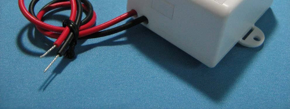
Click to zoom
Application Details
- Equipment Class
- DSR - Part 15 Remote Control/Security Device Transceiver
- Date of Grant
- Nov 09, 2007
- Application Purpose
- Original Equipment
- Date of Application
- Nov 09, 2007
- Equipment Note
- LV DC SE(Lighting system extender)
- Frequency Range
- 433.84500000 - 433.99500000
- Company
- GlobalTop Technology Inc.
- Country
- Taiwan
Documents & Files
Document Text
Text extracted from the exhibit documents filed with the FCC. Open a document above to read the original.
Users Manual
Page 1 of 2 L-INST-LVDC SE 092707 LOW VOLTAGE DC SYSTEM EXTENDER INSTALLATION Install Switches in a Fraction of the Time ... at a Fraction of the Cost TM How System Extenders Work A Lightning ® System Extender acts as a "Repeater" to help your Transmitter's coded signals to reach the desired Receiver(s). The System Extender will repeat any Lightning ® coded signal that it hears. However, only the particular Receiver(s) that have already been "trained" to react to a coded signal will respond to the signal. One or more System Extenders can be used to extend the range of a system and/or to increase the probability of "hitting" Receivers that have been marginally receiving the desired signal. There are two kinds of System Extender: 120V AC Plug-In and Low-Voltage DC Wire-In. These instructions are for the Low Voltage DC Wire-In System Extender. The Low Voltage System Extender will operate on any DC voltage between 6-27 V. This low voltage is defined by agencies such as Underwriters Laboratories as “inherently safe”, so the Low Voltage System Extender can be mounted almost anywhere. You can provide the System Extender with power from an “AC Adapter” that plugs into or is wired into AC power, or you can use a “Power Pack” that incorporates a DC power supply. You can also use batteries or any other source of DC power that you find convenient for your application. The Low Voltage System Extender can be used with either of two different housings: A small rectangular housing or a hemispherical housing. Either one will perform satisfactorily. The difference between the two housings is strictly cosmetic. The hemispherical version looks like a small smoke detector and is designed to mount on a ceiling. The rectangular housing is designed to be used for all other applications. Installing System Extenders If you need to extend the range of a Lightning Switch ® system, the ideal location for the System Extender is usually at the center of the array of Transmitter(s) and Receiver(s). For instance, if the system includes one Transmitter and one Receiver, you would want to locate the Extender about halfway between the two. This approach requires that power be available at the location that you wish to install the Extender. However, even if no power is available anywhere between the Transmitter and the Receiver, (such as between a house and a barn, dock, or detached garage) you can still improve the range and “hit rate” of your system by taking advantage of the exceptional receive/transmit capability of the System Extender. You can do this by wiring a System Extender into electrical power near either the Receiver (preferred) or Transmitter (secondary method). If the System Extender is near the Receiver, its extremely sensitive circuitry will enable it to hear faint signals that might be missed by the Receiver, and the Extender will then retransmit the ID Code to the nearby Receiver. Similarly, because the Lightning ® System Extender transmits the ID Code at a higher signal strength than the Lightning ® Transmitter does, the range and hit probability will both be increased when the Extender repeats a signal that it hears from a nearby Transmitter. Maximizing System Performance There are several things you can do in order to achieve maximum system performance. 1. Mount it up high. The Low Voltage DC System Extender is ideally suited for mounting on or above a ceiling. Regardless of line-of-sight obstructions, a System Extender that is mounted higher generally performs better than one that is mounted relatively low. 2. Try to position the System Extender where it has the fewest obstructions between it and the Transmitters and Receivers that it services. Although the coded radio signal will penetrate walls and even metal plates, each obstruction reduces the signal strength at least a little. For example, you wouldn't want to mount the Extender behind a heavy metal object like a refrigerator. 3. If your system is particularly large or if a great deal of RF noise is present, you might consider adding one or more additional System Extenders. Since a System Extender will repeat any valid ID Lightning ® Code, whether that code comes from a Transmitter or another System Extender, you can "chain" two or more System Extenders to create a very large and highly efficient system. Installing more than one System Extender Each System Extender comes from the factory ready to use - just wire it in and you're ready to go. But if you use more than one System Extender in the same system, you should "Set Up" the Extenders so they’ll work more efficiently together. To do this, simply wire in the new System Extender, wait 5 seconds for it to initialize and then press the "Set Up" button one time. The new Extender will check if any other System Extenders are already present and the entire system will self-adjust for optimal performance. It’s not necessary to press the "Set Up" button again on System Extenders that had already been installed. ® Page 2 of 2 L-INST-LVDC SE 092707 10 Year Limited Warranty Lightning ® products are warranted by PulseSwitch Systems, LC to be free of defects in materials and workmanship at the time of sale within 10 years of the delivery of the product. Our obligation under this warranty is limited to, at our sole option, the repair, replacement or refund of the original purchase price of any product proved to be defective within 10 years from the date of delivery. The defective product must be returned to us by the purchaser and must be accompanied with the original proof of purchase. This limited warranty applies to home use only and does not cover damage from any commercial use or from neglect, misuse, contamination, alteration, accident or abnormal conditions of operation or handling, including failures caused by use outside of the product's specifications, or normal wear and tear of mechanical components. This warranty covers the original purchaser only and is not transferable. This warranty is valid o…
Text truncated - open the document above for the full version.
Cover Letter(s)
1 Lucy Tsai From: debby.dai [[email protected]] Sent: Thursday, November 08, 2007 10:05 PM To: Lucy Tsai Subject: Re: GlobalTop Technology Inc. , FCC ID: U95-LVDCSE, Assessment NO.: AN07T7338, Notice#1 --補件通知 請各位大大協助 Attachments: 71009403-RP1_GlobalTop LV DC SE_E-WDCP2.pdf Dear Lucy, Please see reply below in red. Please see attached revised report per your requirement. Best Regards, Debby Dai 戴妤如 Compliance Certification Services, Inc / Tainan Lab. 程智科技股份有限公司 台南實驗室 TEL: 06-5980808 # 607 FAX: 06-5987878 e-mail: [email protected] 6F., No.605, Jhongshan RD., Sinhua Township, Tainan County 71243, Taiwan 台南縣新化鎮中山路605號6樓 ----- 轉呈者 daphne.liang/ccsemc 於 2007/11/02 05:05 PM ----- "Lucy Tsai" <[email protected]> 2007/11/02 05:04 PM 收件人: "application" <[email protected]> 副本抄送: "daphne.liang" <[email protected]> 主旨: FW: GlobalTop Technology Inc. , FCC ID: U95-LVDCSE, Assessment NO.: AN07T7338, Notice#1 Hi Debby, Please address following issues. Q#1: According to the operational description, the extender can receive the signal from other transmitter and then transmit the signal back to the transmitter that should be defined as a transceiver and the equipment code shall be CSR but not CSC. Please confirm. Debby: Noted, please help us to correct the equipment code to CSR. Q#2: Please clarify whether the device will be activated automatically or manually. The test report indicates the device is activated manually, the transmission time is calculated after the button is released. It seems the device only has a "Setup" button. Please explain which button is used for testing. Debby: The Setup button of EUT isn't for transmission. The EUT is triggered by pressing another device which will provide a pulse to active EUT. Q#3: Please clarify which section is followed. Test report indicates 15.231(e) is followed but the limit of radiated calculation is followed 15.231(b). Please clarify. Besides, per ANSI C63.4, when average detector function limits are specified for a pulse- modulated transmitter, the average level of emission may be found by measuring the peak 2 level of the emissions and correcting them with the duty cycle. The peak value shall be what you measured but not to add correction factor again. Please correct. Debby: Please see attached revised report,shown in page 17. Best Regards, Lucy The items indicated above must be submitted before processing can continue on the above referenced application. Failure to provide the requested information within 30 days of the original e-mail date may result in application dismissal and forfeiture of the filing fee. Also, please note that partial responses increase processing time and should not be submitted. Any questions about the content of this correspondence should be directed to the e-mail address listed below the name of the sender. ________________________________________________________________________ This e-mail transmission is confidential and intended solely for being reviewed by the recipient(s) identified above. If you are not an identified recipient, please ensure that this communication remains confidential and promptly return it to the sender. Please contact immediately by phone (Tel: 886-2-2299-9720) for any problem with this transmission. Thank you for your attention.
External Photos
Compliance Certification Services Inc. Report No.:71009403-RP1 External Photo ( Model :E-WDCP2 )
ID Label/Location Info
g Company : GlobalTop Technology Inc. Model: E-WDCP2 Product : LV DC SE Label Here
Internal Photos
Compliance Certification Services Inc. Report No.:71009403-RP1 External Photo ( Model :E-WDCP2 ) Compliance Certification Services Inc. Report No.:71009403-RP1 Internal Photo Compliance Certification Services Inc. Report No.:71009403-RP1 Compliance Certification Services Inc. Report No.:71009403-RP1
Parts List/Tune Up Info
E-WDCP2 Antenna Specification: Company GlobalTop Technology Inc. Manufacture GlobalTop Technology Inc. Antenna Gain 0 dBi Antenna Type Helical Antenna Antenna Frequency 433.845~433.95Hz
Test Report
Compliance Certification Services Inc. Report No.: 71009403-RP1 FCC ID: U95-LVDCSE Date of Issue: October 26, 2007 Note: This report shall not be reproduced except in full, without the written approval of Compliance Certification Services Inc. This document may be altered or revised by Compliance Certification Services Inc. personnel only, and shall be noted in the revision section of the document. Page 1 Total Page: 25 FCC 47 CFR PART 15 SUBPART C ANSI C63.4: 2003 TEST REPORT For LV DC SE Model: E-WDCP2 Issued to GlobalTop Technology Inc. No. 16 Nan-Ke 9th Rd. Science-based Ind. Park, Tainan 741, Taiwan, R.O.C. Issued by Compliance Certification Services Inc. Ta i n a n L a b . No. 8, Jiu Cheng Ling, Jiaokeng Village,Sinhua Township, Tainan Hsien 712, Taiwan R.O.C. TEL: 886-6-580-2201 FAX: 886-6-580-2202 Compliance Certification Services Inc. Report No.: 71009403-RP1 FCC ID: U95-LVDCSE Date of Issue: October 26, 2007 Page 2 TABLE OF CONTENTS 1. TEST RESULT CERTIFICATION............................................................................................. 3 2. EUT DESCRIPTION .................................................................................................................... 4 3. TEST METHODOLOGY ............................................................................................................. 5 3.1 EUT CONFIGURATION.............................................................................................................. 5 3.2 EUT EXERCISE......................................................................................................................... 5 3.3 GENERAL TEST PROCEDURES.................................................................................................. 5 3.4 FCC PART 15.205 RESTRICTED BANDS OF OPERATIONS .............................................. 6 3.5 DESCRIPTION OF TEST MODES................................................................................................. 6 4. INSTRUMENT CALIBRATION................................................................................................. 6 5. FACILITIES AND ACCREDITATIONS ................................................................................... 7 5.1 FACILITIES.............................................................................................................................. 7 5.2 EQUIPMENT............................................................................................................................. 7 5.3 LABORATORY ACCREDITATIONS AND LISTING....................................................................... 7 5.4 TABLE OF ACCREDITATIONS AND LISTINGS............................................................................ 8 6. SETUP OF EQUIPMENT UNDER TEST .................................................................................. 9 6.1 SETUP CONFIGURATION OF EUT.............................................................................................. 9 6.2 SUPPORT EQUIPMENT.............................................................................................................. 9 7. FCC PART 15.231 REQUIREMENTS...................................................................................... 10 7.1 20 DB BANDWIDTH .......................................................................................................... 10 7.2 LIMIT OF TRANSMISSION TIME.............................................................................................. 12 7.3 DUTY CYCLE ..................................................................................................................... 14 7.4 RADIATED EMISSIONS........................................................................................................... 17 7.5 POWERLINE CONDUCTED EMISSIONS.................................................................................... 23 Compliance Certification Services Inc. Report No.: 71009403-RP1 FCC ID: U95-LVDCSE Date of Issue: October 26, 2007 Page 3 1. TEST RESULT CERTIFICATION Applicant: GlobalTop Technology Inc. No. 16 Nan-Ke 9th Rd. Science-based Ind. Park, Tainan 741, Taiwan, R.O.C. Manufacture: GlobalTop Technology Inc. No. 16 Nan-Ke 9th Rd. Science-based Ind. Park, Tainan 741, Taiwan, R.O.C. Equipment Under Test: LV D C S E Model Number: E-WDCP2 Date of Test: October 12, 2007 ~ October 18, 2007 APPLICABLE STANDARDS STANDARD TEST RESULT FCC 47 CFR Part 15 Subpart C ANSI C63.4 : 2003 No non-compliance noted We hereby certify that: The above equipment was tested by Compliance Certification Services Inc. The test data, data evaluation, test procedures, and equipment configurations shown in this report were made in accordance with the procedures given in ANSI C63.4: 2003 and the energy emitted by the sample EUT tested as described in this report is in compliance with conducted and radiated emission limits of FCC Rules Part 15.207, 15.209 and Part 15.231. The test results of this report relate only to the tested sample identified in this report. Approved by: Reviewed by: October 26, 2007 October 26, 2007 Jeter Wu Eric Yang Section Manager Engineer Compliance Certification Services Inc. Compliance Certification Services Inc. Compliance Certification Services Inc. Report No.: 71009403-RP1 FCC ID: U95-LVDCSE Date of Issue: October 26, 2007 Page 4 2. EUT DESCRIPTION Product LV D C S E Model Number E-WDCP2 Model Description Low Voltage DC System Extender Model Difference N/A Operating Frequency From 433.845 MHz to 433.995kHz Type of Modulation DTS EUT Type Engineering Sample. Product Sample, Mass Product Sample. Power Supply 6~27VDC Antenna Specification 0dBi, Helical Antenna, GlobalTop Temperature Range 0°C ~ +55°C REMARK: This submittal(s) (test report) is intended for FCC ID:U95-LVDCSE filing to comply swith Section 15.207, 15.209 and 15.231 of the FCC Part 15, Subpart C Rules. Compliance Certification Services Inc. Report No.: 71009403-RP1 FCC ID: U95-LVDCSE Date of Issue: October 26, 2007 Page 5 3…
Text truncated - open the document above for the full version.
Test Setup Photos
Compliance Certification Services Inc. Report No.: 71009403-RP1 FCC ID: U95-LVDCSE Date of Issue: October 26, 2007 Page 24 APPENDIX 1 PHOTOGRAPHS OF TEST SETUP Radiated Emission Set up Photos (For TX) (1) X-axis Compliance Certification Services Inc. Report No.: 71009403-RP1 FCC ID: U95-LVDCSE Date of Issue: October 26, 2007 Page 25 End of report
Contact Information
Applicant
Yingjie Huang(Engineer)
Test Firm
Compliance Certification Services Inc.Daphne Liang
Technical Specifications
| # | Rule Parts | Frequency Range | Power Output |
|---|---|---|---|
| 1 | 15.231 | 433.845 MHz - 433.995 MHz | - |
Other Applications from GlobalTop Technology Inc.

U95-TOUCHGPS
Oct 16, 2007Bluetooth GPS Receiver
Equipment Class
DSS - Part 15 Spread Spectrum Transmitter