
FCCID.CO- FCC ID Database
HomeCompaniesEquipment ClassesSearch

© 2026 FCC ID Database. All rights reserved.

AboutContactData sourced from FCC public records
  1. Home/
  2. GENESIS TECH CO., LTD./
  3. UA7GT170M

UA7GT170M17" TFT LCD MONITOR

GENESIS TECH CO., LTD.
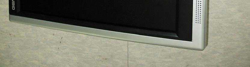
17" TFT LCD MONITOR - FCC ID UA7GT170M - GENESIS TECH CO., LTD.
Click to zoom

Application Details

Equipment Class
JBP - Part 15 Class B Computing Device Peripheral
Date of Grant
Jun 01, 2006
Application Purpose
Original Equipment
Date of Application
Jun 01, 2006
Equipment Note
17" TFT LCD MONITOR
Company
GENESIS TECH CO., LTD.
Country
South Korea

Documents & Files

Select a file to view
Users Manual

↗

Block Diagram

↗

External Photos

↗

ID Label/Location Info

↗
↗

Internal Photos

↗

Test Report

↗

Test Setup Photos

↗

Document Text

Text extracted from the exhibit documents filed with the FCC. Open a document above to read the original.

Users Manual

USER’S GUIDE GT170M LCD Monitor 2 3 The information contained in this document is subject to change without notice. This document contains proprietary information that is protected by copyright. All rights are reserved. No part of this document may be reproduced, translated to another language or stored in a retrieval system, or transmitted by any means, electronic, mechanical, photocopying, recording, or otherwise, without prior written permission. Windows is a registered trademark of Microsoft Inc. Other brand or product names are trademarks of their respective holders. 4 5 TABLE OF CONTENTS FOR YOUR SAFETY For Your Safety -------------------------------------------------------------------------------------6 GENERAL NOTES 1. Introduction--------------------------------------------------------------------------------------8 1.1 General Information 1.2 Features 1.3 Check List 2. Installation --------------------------------------------------------------------------------------9 2.1 Installing the base 2.2 Installing the monitor 2.3 Self test pattern 2.4 Adjusting picture 3. Operation of the monitor -----------------------------------------------------------------11 3.1 Power on/off switch 3.2 Power LED indicator 3.3 OSD control keys 3.4 Safety mode 3.5 Timing guide 3.6 Plug & Play 3.7 Power management 3.8 Volume adjust 4. Specifications ---------------------------------------------------------------------------------17 5. Simple Troubleshooting -------------------------------------------------------------------18 6 FOR YOUR SAFETY Before operating the monitor, please read this manual thoroughly. This manual should be retained for future reference. FCC Class B Radio Frequency Interference Statement WARNING: (FOR FCC CERTIFIED MODELS) NOTE: This equipment has been tested and found to comply with the limits for a Class B digital device, pursuant to Part 15 of the FCC Rules. These limits are designed to provide reasonable protection against harmful interference in a residential installation. This equipment generates, uses and can radiate radio frequency energy, and if not installed and used in accordance with the instructions, may cause harmful interference to radio communications. However, there is no guarantee that interference will not occur in a particular installation. If this equipment does cause harmful interference to radio or television reception, which can be determined by turning the equipment off and on, the user is encouraged to try to correct the interference by one or more of the following measures: 1. Reorient or relocate the receiving antenna. 2. Increase the separation between the equipment and receiver. 3. Connect the equipment into an outlet on a circuit different from that to which the receiver is connected. 4. Consult the dealer or an experienced radio/TV technician for help. LAMP(S) INSIDE THIS PRODUCT CONTAIN MERCURY AND MUST BE RECYCLED OR DISPOSED OF ACCORDING TO LOCAL, STATE OR FEDERAL LAWS. FOR MORE INFORMATION, CONTACT THE ELECTRONIC INDUSTRIES ALLIANCE AT WWW.EIAE.ORG . FOR LAMP SPECIFIC DISPOSAL INFORMATION CHECK WWW.LAMPRECYCLE.ORG . NOTICE: 1. The changes or modifications not expressly approved by the party responsible for compliance could void the user's authority to operate the equipment. 2. Shielded interface cables and AC power cord, if any, must be used in order to comply with the emission limits. 3. The manufacturer is not responsible for any radio or TV interference caused by unauthorized modification to this equipment. It is the responsibilities of the user to correct such interference. WARNING: To prevent fire or shock hazard, do not expose the monitor to rain or moisture. Dangerously high voltages are present inside the monitor. Do not open the cabinet. Refer servicing to qualified personnel only. 7 PRECAUTIONS 1. Unplug the monitor from the power source when you clean the monitor. Do not use liquid cleaners or aerosol cleaners. Use a cloth to clean it. If that doesn’t do, please use LCD screen cleaners. 2. Do not use attachments not recommended as they may cause hazards. 3. Please grasp the plug to unplug the connector from the wall outlet. Do not pull the power cord to unplug it. 4. Do not place anything on the power cord or step on it 5. Do not place the monitor near water such as bathtub, washbowl, sink, laundry tub, swimming pool etc. 6. The slots are designed for ventilation they keep the monitor both workable and protect it from overheating. For the same reason, please do not place the monitor on a bed, sofa, carpets or other similar surface. Do not place the monitor near or over a heat source, or place in a enclosed structure/area. 7. Keep the monitor at least 2 inches (5 cm) away from the wall or other goods. 8. This monitor can only use the power source indicated on the label. If you have questions, please consult your dealer. 9. As a safety measure, this monitor is equipped with a three-wire ground style plug. If you can not insert the plug into outlet, contact your electrician to install the correct outlet, or use an adapter to ground the appliance safely. Do not bypass the safety purpose of the grounding-type plug. 10. Please make sure that the outlet and power cord can support the total electricity use of the products. 11. Place the monitor in safe place where the cord will not be easily tripped over. 12. Follow all the warnings and instructions illustrated in the manual. 13. Don’t overload the wall outlets and extension cords as this can result in fire or electric shocks. 14. Do not remove or open the cover to service this monitor yourself. It may expose you to dangerous voltage or other hazards. Please refer all servicing to qualified service personnel. 15. Unplug this monitor from the outlet and refer servicing to qualified service personnel under the following conditions. A. The power cord is frayed or damaged. B. The monitor has been dropped or the cabinet has been damaged C. When the monitor displays a distinct change in performa…

Text truncated - open the document above for the full version.

External Photos

Photographs of EUT Front View Rear View

ID Label/Location Info

Sample Label

ID Label/Location Info

Page: 15 of 30 . . Report No.: STD-FCC-06007 STANDARD ENGINEERING www.stdeng.com Standard Engineering Co. Ltd. 377-11 Sinjang-Ri, Eumam-Myeon EMC Laboratory Seosan-Si, Chungnam, Korea Tel.: +82-41-663-9436, Fax :+82-41-663-9434 e-mail: [email protected] 6. Attachments 6.1 Sample Label Labeling Requirements per section 2.925 & 15.19 The label shown shall be permanently affixed at a conspicuous location on the device and be readily visible to the user at the time of purchase.

Internal Photos

Inside View Main Board Front Main Board Rear Inverter Board Front Inverter Board Rear LCD Panel Rear

Test Report

Page: 1 of 30 . . Report No.: STD-FCC-06007 STANDARD ENGINEERING www.stdeng.com Standard Engineering Co. Ltd. 377-11 Sinjang-Ri, Eumam-Myeon EMC Laboratory Seosan-Si, Chungnam, Korea Tel.: +82-41-663-9436, Fax :+82-41-663-9434 e-mail: [email protected] Test Report for Part 15 Report number: STD-FCC–06007 Type of EUT: 17” TFT LCD Monitor Model number: GT170M Applicant: GENESIS TECH CO., LTD. Applied standards: FCC Part 15 Subpart B(Class B) The above mentioned EUT had been tested by EMC Laboratory of Standard Engineering Company in order to confirm the compliance with the requirements of FCC rules and this test was executed in accordance with the measurement method specified in ANSI C63.4-2003 I hereby certify that the accuracy of test-data is true and correct with my best knowledge and belief. Also I prove this measurement was performed by qualified person. Date of tested: 2006-05-26 Date of Issued: 2006-05-27 Tested by: Approved by: SM Kim / Test Engineer SS Seo / Senior Researcher Page: 2 of 30 . . Report No.: STD-FCC-06007 STANDARD ENGINEERING www.stdeng.com Standard Engineering Co. Ltd. 377-11 Sinjang-Ri, Eumam-Myeon EMC Laboratory Seosan-Si, Chungnam, Korea Tel.: +82-41-663-9436, Fax :+82-41-663-9434 e-mail: [email protected] Contents 1. General information 1.1 Product information 1.2 Client information 2. Information of EMC Laboratory 3. Procedure of measurement 3.1 Conducted emission 3.1.1 Configuration of measurement 3.1.2 Detector function selection and bandwidth 3.1.3 Frequency range to be scanned 3.1.4 Line impedance stabilization network (LISN) 3.2 Radiated emission 3.2.1 Configuration of measurement 3.2.2 Detector function selection and bandwidth 3.3 Method of calculation 4. Environment of measurement 4.1 Condition of environment 4.2 Measurement uncertainty 4.3 List of Test equipments 4.4 List of peripherals and cables 4.5 Configuration of EUT 4.6 Rating and Physical Characteristics 5. Result of measurement 5.1 Conducted emission 5.1.1 Test data 5.1.2 Result 5.2 Radiated emission 5.2.1 Test data 5.2.2 Result Page: 3 of 30 . . Report No.: STD-FCC-06007 STANDARD ENGINEERING www.stdeng.com Standard Engineering Co. Ltd. 377-11 Sinjang-Ri, Eumam-Myeon EMC Laboratory Seosan-Si, Chungnam, Korea Tel.: +82-41-663-9436, Fax :+82-41-663-9434 e-mail: [email protected] 6. Attachment 6.1 Sample Label 6.2 Photographs of Set-up 6.3 Photographs of EUT 6.4 Conducted emission data 6.5 Block Diagram/Circuit 6.6 User’s Manual Page: 4 of 30 . . Report No.: STD-FCC-06007 STANDARD ENGINEERING www.stdeng.com Standard Engineering Co. Ltd. 377-11 Sinjang-Ri, Eumam-Myeon EMC Laboratory Seosan-Si, Chungnam, Korea Tel.: +82-41-663-9436, Fax :+82-41-663-9434 e-mail: [email protected] 1. General Information 1.1 Product information Description of EUT : 17” TFT LCD Monitor Model number : GT170M Specification : Adaptor Input : AC100-240V, 50/60Hz Adaptor Output : DC12V, 4.12A Applied Standard : FCC Part 15 subpart B (Class B) Test method : ANSI C63.4 - 2003 1.2 Client information Applicant : GENESIS TECH CO., LTD. Address : #611 C-dong, Woolim Lion's Valley 425, Cheongcheon- dong, Bupyeong-gu, Incheon Korea Phone No. : +82-32-623-7900 Fax. No. : +82-32-623-7988 Contact person : JunHyeong Cho/Assistant Manager Manufacturer : GENESIS TECH CO., LTD. Address : #611 C-dong, Woolim Lion's Valley 425, Cheongcheon- dong, Bupyeong-gu, Incheon Korea Phone No.: +82-32-623-7900 Fax. No.: +82-32-623-7988 Page: 5 of 30 . . Report No.: STD-FCC-06007 STANDARD ENGINEERING www.stdeng.com Standard Engineering Co. Ltd. 377-11 Sinjang-Ri, Eumam-Myeon EMC Laboratory Seosan-Si, Chungnam, Korea Tel.: +82-41-663-9436, Fax :+82-41-663-9434 e-mail: [email protected] 2. Information of EMC Laboratory Name of test laboratory Standard Engineering Co., Ltd. Location 377-11 Sinjang-Ri, Eumam-Myeon, Seosan-Si Chungnam, Korea Phone No. : +82-41-663-9436~7 Fax. No. : +82-41-663-9434 FCC Filing Number : 624439 Environment of Laboratory This location can keep accuracy in measuring more than anywhere because surrounding noise ambient is low and silent excellently to be suitable in EMI's measuring. Map Page: 6 of 30 . . Report No.: STD-FCC-06007 STANDARD ENGINEERING www.stdeng.com Standard Engineering Co. Ltd. 377-11 Sinjang-Ri, Eumam-Myeon EMC Laboratory Seosan-Si, Chungnam, Korea Tel.: +82-41-663-9436, Fax :+82-41-663-9434 e-mail: [email protected] 3. Procedure of measurement 3.1 Conducted emissions 3.1.1 Configuration of measurement This measurement executed in shield-room and EUT was tested on 0.8m height wooden table located on the floor with 0.1m distance from the reference ground plane. EUT's rear part had a distance from VCP(Vertical Conducted Plane) with 0.4m length and LISN placed on the grounded plane with 1m distance from EUT's side part . Excess power cord and cables fixed in bundle style of 30~40cm length with non-inductive material, and power line was connected to power source through LISN to detect maximum EMI without external RFI from aux. instruments. For the measurement, ‘H’ scroll pattern was applied to the EUT with maximum resolution (1280x1024) in order to detect maximum electromagnetic disturbance from the EUT. Measuring equipments and EUT confirmed that warming-up was performed during enough time and calibration of antenna as well as calibration of measuring equipment also completed beforehand. This measurement was performed on condition of worst-case emission. 3.1.2 Detector function selection and bandwidth During conducted emission measurement, a radio noise meter that has a CISPR quasi-peak detector with 10 kHz IF bandwidth of 6 dB was utilized. 3.1.3 Frequency range to be scanned For conducted emissions measurement, frequency range of 150 kHz to 30 MHz included, was investigated. 3.1.4 Line impedance stabilization network (LISN) A LISN with characteristics that conform to the requirements of ANSI C63.4-1992 was used for the measurement of conducted power-line radio noise; (50 micro-henries / 50 ohms). Chassis and earth-p…

Text truncated - open the document above for the full version.

Test Setup Photos

Photographs of Set-up Conducted emission test (Front) Conducted emission test (Rear) Radiated Emission (Front) Radiated Emission (Rear)

Contact Information

Applicant

Jun Hyeong Cho(Assistant Manager)
[email protected]82-32-623-7900Fax: 82-32-623-7988

Test Firm

Standard Engineering Co., Ltd.Jang-Yul Ahn
[email protected]82-41-663-9436Fax: 82-41-663-9434

Technical Specifications

#Rule PartsFrequency RangePower Output
115B--

Other Applications from GENESIS TECH CO., LTD.

19" TFT LCD MONITOR - FCC ID UA7GT190M - GENESIS TECH CO., LTD.
UA7GT190M

19" TFT LCD MONITOR

Jun 01, 2006

Equipment Class

JBP - Part 15 Class B Computing Device Peripheral