UBLSIU3ARadio Alarm Transmitter
Stealth Alarm Systems Inc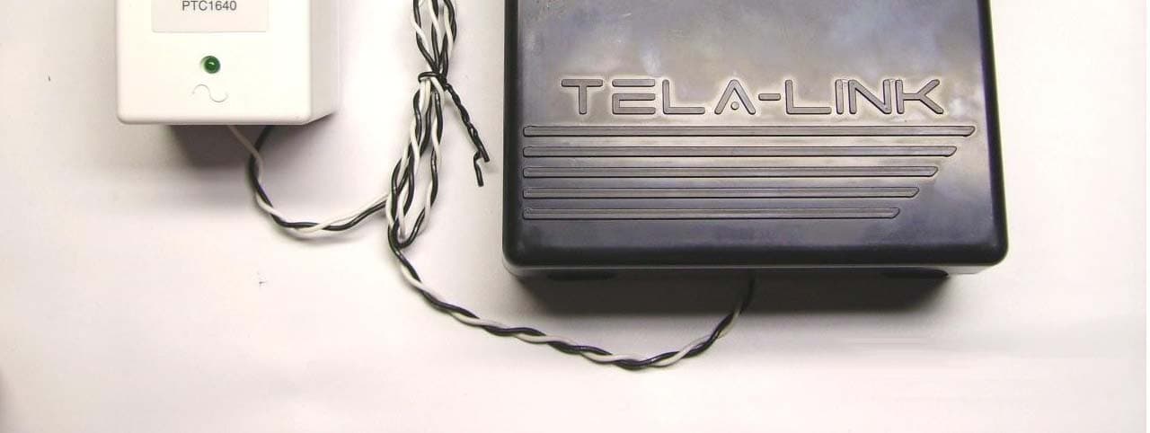
Click to zoom
Application Details
- Equipment Class
- TNB - Licensed Non-Broadcast Station Transmitter
- Date of Grant
- Jul 20, 2006
- Application Purpose
- Original Equipment
- Date of Application
- Jul 20, 2006
- Equipment Note
- Radio Alarm Transmitter
- Frequency Range
- 450.00000000 - 470.00000000
- Company
- Stealth Alarm Systems Inc
- Country
- Canada
Documents & Files
Document Text
Text extracted from the exhibit documents filed with the FCC. Open a document above to read the original.
Users Manual
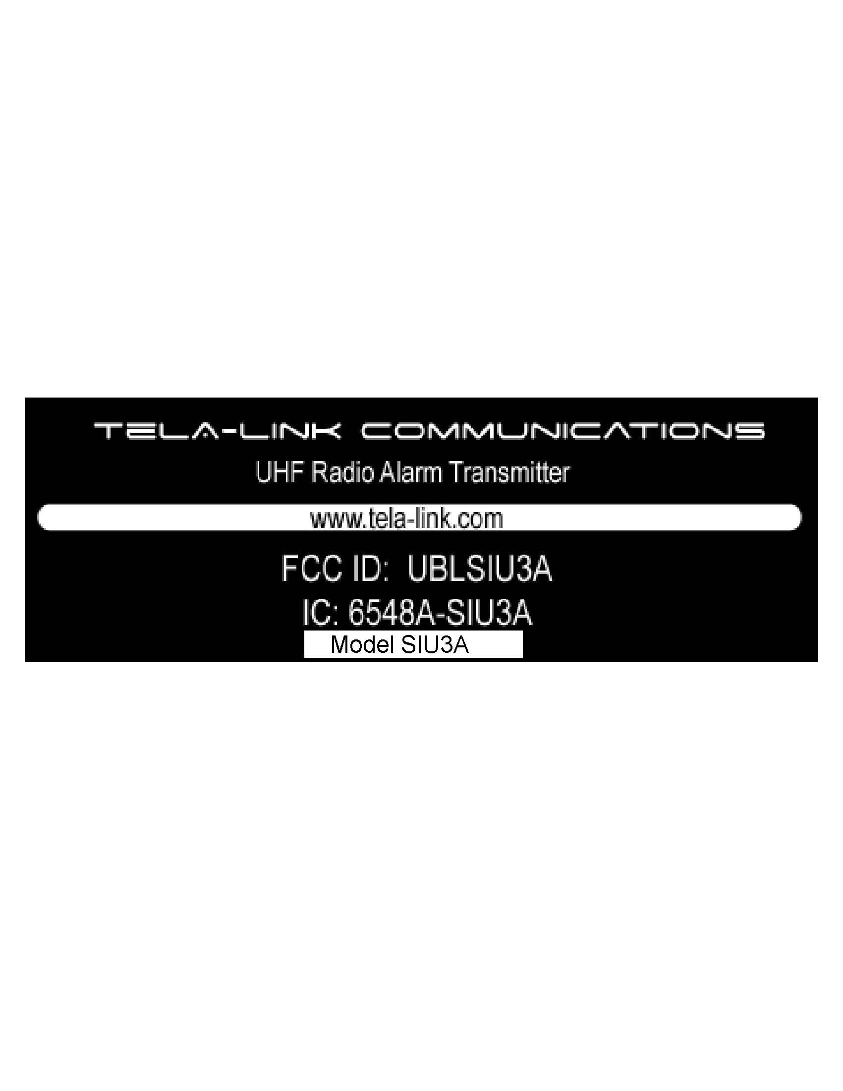
1 2 Licensing The FCC and IC requires the radio to operate with their respective guidelines, this includes licensing. The Stealth Corporation have applied and received operating licenses within each area the Tela-Link ™ units are distributed to within the StarNet coverage placement area. No further Licensing within those areas are required from the end user. Although the end user / dealer must upon the respective agency request give immediate access for inspection and testing. Exposure To Radio frequency energy The Tela-Link ™ transmitter is active when the device senses an alarm event. When the Tela-Link ™ transmitter is active it emits up to .6watts (EIRP) of (RF) radio frequency energy (note this rating includes averaging for duty cycle for RF exposure purposes) This product has been evaluated for compliance with the maximum permissible exposure for RF energy at the maximum power rating of the unit with the built in antenna. The antennas used for this device must be installed to provide a separation distance of at least 20 cm (7.9 inches) from the from all persons and must not be co-located or operating in conjunction with any other antenna or transmitter. For external antenna connection, the maximum antenna gain must not exceed 5 dBi or FCC/IC compliance will be void The antenna tested for this product for RF exposure was the StarNet TE-SANT-3. This is the only antenna available through StarNet. Other antennas may require lesser or greater distances of connector cable to meet the limits depending upon their gains relative to that test. Higher gain antenna are capable of yielding a higher RF energy density in the strongest part of their field and would, therefore, require a greater separation from the antenna. If other antennas are used, it is incumbent upon the installer to insure that the RF exposure limits for General Population/Uncontrolled Exposure are met. See 47CFR1.1307(b)(1)-(3) and / or OET Bulletin 65, Edition 97-01 for more information on RF exposure guidelines. fcc Label/Warnings An FCC label must be visible on the units in its final configuration. If the unit is to be used as shipped from StarNet, this would be no problem since the FCC label is affixed to outside at the bottom of the housing. This label is rate for harsh conditions and is not easily removed or damaged and contains FCC code UBLSIU3A. Any modifications to this product may void the FCC compliance Safety Standards The FCC (with its action in General Docket 79-144, March 1985) has adopted a safety standard for human exposure to radio frequency electromagnetic emitted by FCC regulated equipment. StarNet observes these guidelines and recommends that you do also: · DO NOT hold the Tela-Link ™ SIU3 so the antenna is very close to or touching exposed parts of the body, especially the face or eyes, while transmitting. · DO NOT operate radio equipment near electrical blasting caps or in an explosive atmosphere. · DO NOT allow children to play with any radio equipment that contains a transmitting device · REPAIR of Tela-Link ™ products should only be performed by StarNet authorized personnel. General Specifications FCC ID: UBLSIU3A IC ID: 6548A-SIU3A Frequency range Canada: 406.1 - 430 MHz and 450 - 470 MHz USA: 416 MHz - 430 MHz and 450 – 470 MHz Bandwidth 6 KHz per spectral mask E Synthesizer Step Size 6.25 KHz FCC Rule Parts 90 IC Class RSS-119 RF Channels 1 Frequency Stability < 0.5 PPM (-30 to +50 C) Data Rate 4800 bps Power Consumption 12 - 14 VDC or 12 - 17 VAC Standby 120 mA Transmit 600 mA Dimensions 9¼“H x 6¼“W x 2¼“D or 236mmH x 159mmW x 58mmD Weight 13.8 oz or 390 grams (without battery) Transmitter Duty Cycle < 1% Storage Temperature -40 to +85 C, 10% - 90% RHNC Operating Temperature -30 to +50 C 3 Table of Contents 4 5 features • Transmits alarm information to a dedicated long-range radio network • Features Six (6) discrete alarm zones keypad programmable FULLY programmed before shipping. The Tela-Link™ (TLR) is complete with a default program and is operational without programming. flash memory The Tela-Link™ (TLR) uses Flash memory, which will retain all program information even if AC and battery power is removed. The Flash memory can be reprogrammed thousands of times. Static / Lightning Protection The Tela-Link™ (TLR) radio network, known as StarNet Radio Communications™, has been carefully designed and tested to provide reliable protection against static and lightning induced transients. Our special “Zap-Out” circuit board design catches high voltage transients right at the wiring terminals, and transient protection devices are placed in all critical areas to further reduce damaging voltages. Supervision • Low or disconnected external battery • Loss of external AC power • Long-Range Radio Alarm Transmitter • Six (6) zone inputs for stand-alone operation • Trouble Reporting Codes and Test Transmission Reporting Code • Programmable Test Transmission Time • Programmable zone response time • Inputs for external power supply trouble indications • System Clock and Date • Installer Lockout feature • Programmed with the TL 360 LED keypad specifications • Six (6) positive or negative triggered zone inputs -positive voltage trigger: 4 to 14 VDC -negative voltage trigger: 0 to 0.8 VDC -input impedance: 10kΩ -maximum zone loop resistance: 100Ω IMPORTANT: Alarm Dealers must be enrolled with StarNet Radio Communications to activate a Tela-Link Transmitter. If you have already enrolled, Please Call 1-888-207-STAR (7827) CANADA or 1-800-246-1914 USA at least 24-hours prior to install. 6 • 2 negative triggered trouble inputs -negative voltage trigger: 0 to 0.8 VDC • Output: 50mA • Programmable with the TL 360 Keypad installation Locating the TelA-Link™ (TLR) Mount the TLR cabinet in a convenient location above ground level. As much as is reasonably possible, do not mount the TLR near sources of interference. These include sources of electrical noise such as computers, televisions and electric motors in appliances a…
Text truncated - open the document above for the full version.
Cover Letter(s)
RE: Stealth Alarm Systems Inc os Tela-Link FCC ID: UBLSIU3A Tim, Here are the responses to your enquiries. Please also note due to some changes and retests to get compliance for radiated emissions, the following updated additional exhibits have been uploaded to the website: 1. Internal photographs 2. BOM 3. Schematics 4. New Test report 1) Please provide a parts list for this device. As a minimum this must include the active components in the RF circuitry. Response: A new BOM has been uploaded to the ATCB website 2) Please provide a Tune up procedure over the power range provided (2.1033(c)(9)). Note that information in the operational description explains factory calibrations. This information should be included in the Tune up procedure. Response: The description below has also been added to the Test report in section 2 The production tune-up procedure is as follows. With EUT in test mode set to maximum power and transmitting four packets per second, measure the power at the bottom, bottom middle, top middle and top frequencies (406.1, 430, 450, 470 MHz). If the power is within 33 +/- 1 dB, make no further adjustments. If the power is more than +/- 1 dB send commands to the microprocessor to reduce the gate bias on the PA until the power is within spec. The gate bias is controlled by a pulse-width-modulated output of the microprocessor. The PWM frequency is approximately 100 kHz. 3) It does not appear that the application includes both DC voltages AND currents applied into the several elements of the final radio frequency amplifying device for normal operation over the power range been provided? (2.1033(c)(8)). Please provide or kindly explain where this information may be found. Response: The description below has also been added to the revised test report in section 2 The typical operating parameters for the PA are Vdd = 10.0 V Id = 500 mA typical 4) If necessary, please update the confidentiality to include the parts list and tune up procedures provided. Response: Updated to include BOM 5) 731 form cites frequency range of 406.1 – 470 while operational description cites 410 – 470 MHz and users manual cites 410 – 430 & 450 – 470 and test report cites 410.6 – 430 & 450 – 470 and test data shows 406.1 – 430 & 450-470. Please explain/correct these inconsistencies as necessary. Response: These errors have been corrected, the correct frequency ranges are 406.1 MHz - 430 MHz and 450 MHz – 470 MHz for Canada and 416 MHz – 430 MHz and 450 to 470 MHz for the USA 6) The information provided mentions both an internal and external antenna. Please update the RF exposure information to clearly explain the gains associated with each antenna and the worse case is selected for calculations. Additionally, please note that a 1.0 dBi is listed for antenna gain, however dipoles are typically 1.64 numeric (theoretical) or similar Response: A new RF exposure exhibit has be uploaded. The maximum gain for any external antenna is 5 dBi . 7) Kindly explain why the RF exposure shows 25.9 cm, while the manual shows much more distance. Did the manufacturer cite a larger distance on purpose? Response: A new manual and RF exposure exhibit has been updated and uploaded to the website 8) RF exposure information in the manual should also caution against co-location, such as the following or similar: The antenna(s) used for this transmitter must be installed to provide a separation distance of at least ___ cm from all persons and must not be co-located or operating in conjunction with any other antenna or transmitter. Response: The manual has been updated 9) Users Manual does not appear to address the RX portion of this system is subject to Part 15 and the manual does not appear to include information required by 15.21 and the label does not appear to include the information required by 15.19(a)(1) (for the RX). Response: This device does not have a receiver, it is a transmitter only 10) This device utilizes a integrated antenna. Given the devices utilizes a integrated antenna (and also external antenna) and the limits are in ERP (90.279 and 90.205), the data should show compliance in ERP. Please correct. Response: The report has been updated to show data relative to ERP limits 11) Sections mentioning power should also cite 90.205 and 90.279 in addition to Part 2. Response: Corrected in updated report 12) Please justify transmissions in the 406 – 416 band. It appears that according to certain sections of Part 90, that: Frequencies in this band will be assigned only for transmitting hydrological or meteorological data or for low power wireless microphones in accordance with the provisions of §90.265. Response: This device will only be marketed for the US in the 416 MHz – 430 MHz, and 450- 470 MHz bands. For Canada the band will be extended down to 406.1 MHz as per RSS 119 13) It is difficult to adequately determine if the device complies with the mask portion from 3 to 4.6 kHz given the span used. Please provide an additional plot of the worse case emissions using a span around 10-15 kHz as appropriate. Additionally, mask plots should normally show the masks on the plot itself to show compliance. Please correct. Response: Please see revised test report uploaded to your website which contains new data 14) Figure 7 appears to utilize a duty cycle for purposes of showing compliance. Duty factor is normally not applied to review of the mask. Please utilize the narrower span as given above in effort to obtain better dynamic range and also an appropriate RBW = VBW = 100 Hz. Response: Please see revised report, no duty cycle factor has been applied and measurements have been conducted with RBW and VBW as per your direction. 15) Test report for radiated emissions mentions ANSI C63.4. This is not correct as the method should follow the substitution method of TIA-603. Response: TIA-603 Substitution method was followed, this is a reference error in the report and has been corrected in the revised report 16) For frequency stability,…
Text truncated - open the document above for the full version.
Cover Letter(s)
American Telecommunications Certification Body Inc. 6731 Whittier Ave, McLean, VA 22101 July 6, 2006 RE: Stealth Alarm Systems Inc os Tela-Link FCC ID: UBLSIU3A After a review of the submitted information, I have a few comments on the above referenced Application. 1) Please provide a parts list for this device. As a minimum this must include the active components in the RF circuitry. 2) Please provide a Tune up procedure over the power range provided (2.1033(c)(9)). Note that information in the operational description explains factory calibrations. This information should be included in the Tune up procedure. 3) It does not appear that the application includes both DC voltages AND currents applied into the several elements of the final radio frequency amplifying device for normal operation over the power range been provided? (2.1033(c)(8)). Please provide or kindly explain where this information may be found. 4) If necessary, please update the confidentiality to include the parts list and tune up procedures provided. 5) 731 form cites frequency range of 406.1 – 470 while operational description cites 410 – 470 MHz and users manual cites 410 – 430 & 450 – 470 and test report cites 410.6 – 430 & 450 – 470 and test data shows 406.1 – 430 & 450-470. Please explain/correct these inconsistencies as necessary. 6) The information provided mentions both an internal and external antenna. Please update the RF exposure information to clearly explain the gains associated with each antenna and the worse case is selected for calculations. Additionally, please note that a 1.0 dBi is listed for antenna gain, however dipoles are typically 1.64 numeric (theoretical) or similar. 7) Kindly explain why the RF exposure shows 25.9 cm, while the manual shows much more distance. Did the manufacturer cite a larger distance on purpose? 8) RF exposure information in the manual should also caution against co-location, such as the following or similar: The antenna(s) used for this transmitter must be installed to provide a separation distance of at least ___ cm from all persons and must not be co-located or operating in conjunction with any other antenna or transmitter. 9) Users Manual does not appear to address the RX portion of this system is subject to Part 15 and the manual does not appear to include information required by 15.21 and the label does not appear to include the information required by 15.19(a)(1) (for the RX). 10) This device utilizes a integrated antenna. Given the devices utilizes a integrated antenna (and also external antenna) and the limits are in ERP (90.279 and 90.205), the data should show compliance in ERP. Please correct. 11) Sections mentioning power should also cite 90.205 and 90.279 in addition to Part 2. 12) Please justify transmissions in the 406 – 416 band. It appears that according to certain sections of Part 90, that: Frequencies in this band will be assigned only for transmitting hydrological or meteorological data or for low power wireless microphones in accordance with the provisions of §90.265. 13) It is difficult to adequately determine if the device complies with the mask portion from 3 to 4.6 kHz given the span used. Please provide an additional plot of the worse case emissions using a span z Page 2 July 10, 2006 around 10-15 kHz as appropriate. Additionally, mask plots should normally show the masks on the plot itself to show compliance. Please correct. 14) Figure 7 appears to utilize a duty cycle for purposes of showing compliance. Duty fractor is normally not applied to review of the mask. Please utilize the narrower span as given above in effort to obtain better dynamic range and also an appropriate RBW = VBW = 100 Hz. 15) Test report for radiated emissions mentions ANSI C63.4. This is not correct as the method should follow the substitution method of TIA-603. 16) For frequency stability, please compare to appropriate limits (i.e. 1 ppm FCC, 0.5 ppm IC). 17) For transient frequency behavior, please add appropriate limit lines. For IC: 18) Please adjust the IC labeling to include the model number as being listed, according to IC labeling requirements. 19) Please correct the IC form to: - worse case TX spurious levels and worse case RX emissions. 20) For IC an appropriate RSS-102 attestation should be provided. Please see most recent ATCB IC forms which includes these attestations (attached). Annex B should be provided and Annex A may also need to be provided. Please review. 21) Please provide appropriate receiver emissions according to RSS-119 section 5.12. 22) Please explain if frequencies for Canada are 406-1 – 470 MHz or 406-1 – 430 MHz, and 450 – 470 MHz. Please correct the IC form if relevant. Timothy R. Johnson Examining Engineer mailto: [email protected] The items indicated above must be submitted before processing can continue on the above referenced application. Failure to provide the requested information may result in application termination. Correspondence should be considered part of the permanent submission and may be viewed from the Internet after a Grant of Equipment Authorization is issued. Please do not respond to this correspondence using the email reply button. In order for your response to be processed expeditiously, you must submit your documents through the AmericanTCB.com website. Also, please note that partial responses increase processing time and should not be submitted. Any questions about the content of this correspondence should be directed to the sender.
Cover Letter(s)
NATIONAL TECHNICAL SYSTEMS, INC. www.ntscorp.com 5151 47 th Street NE • Calgary, Alberta T2E 3R2 (403)295-5134 • • (403) 295-4190 fax July 21, 2006 American Telecommunications Certification Body, Inc. 6731 Whittier Avenue Suite C110 McLean, VA 22101 RE: Certification Application FCC ID: UBLSIU3A IC #: 6548ASIU3A Please be advised pursuant to 47CFR 0.459 that the following information is to be held permanently confidential on behalf of Tela -Link Inc • Schematics • Bill of Materials/Parts List • Block Diagram • Operational description • Tune up procedure This application contains technical information that Tela-Link Inc deems to be trade secrets and proprietary. If made public, the information might be used to the disadvantage of the applicant in the marketplace. Thank you for your attention to this matter. Sincerely, Glen Moore EMC Manager NTS On Behalf of Tela link Inc
External Photos
FCC ID: UBLSIU3A CG-336 IC: 6548ASIU3A Stealth Alarm Systems Inc External Photograph Exhibit Top View of System FCC ID: UBLSIU3A CG-336 IC: 6548ASIU3A Stealth Alarm Systems Inc Bottom View of System
Internal Photos
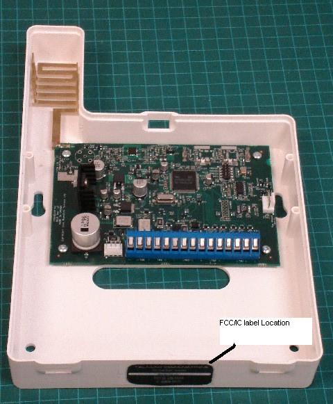
FCC ID: UBLSIU3A CG-336 IC: 6548ASIU3A Stealth Alarms Inc Internal Photograph Exhibit Component side of PCB showing Antenna Integral Antenna External Antenna Port FCC ID: UBLSIU3A CG-336 IC: 6548ASIU3A Stealth Alarms Inc Top Side of PCB Closeup FCC ID: UBLSIU3A CG-336 IC: 6548ASIU3A Stealth Alarms Inc Bottom Side of PCB FCC ID: UBLSIU3A CG-336 IC: 6548ASIU3A Stealth Alarms Inc Top View of System
RF Exposure Info
FCC ID: UBL-SIU3A CG-336 IC: 6548A - SIU3A RF Exposure MPE Exhibit As per OET Bulleting 65 Maximum permissible exposure limit is derived from Freq. (MHz)/1500 = MPE mW/cm 2 406 MHz/1500 = 0.271 mw/cm 2 The following calculations determine what the power density is at a distance of 20 cm. Tx output power conducted = 33 dBm Antenna Gain = 5 dBi or 3.2 numeric gain Duty cycle factor = 10 log 25 ms = -10 dB 250 ms Corrected EIRP = 28 dBm or 600 mW Duty cycle explanation: The duty cycle factor was applied based on the operating conditions of the transmitter, which is designed to transmit for a maximum of 25 ms every 250 ms- 16 seconds, 5 times in sequence then the the transmitter keys off. This transmission sequence only occurs when there is an alarm condition or and alarm system code is typed in by the user (enter/exit premises). Therefore the overall effect on EIRP of the transmitter output power for RF exposure is a reduction in the EIRP to 28 dBm or 600 mW Antenna gain information: This product uses and integral antenna or alternatively can be used with an external antennal. The maximum allowable gain for the external antenna is 5 dbi, which is the gain for the integral antenna. Therefore the worst case gain is 5 dbi MPE Calculation for Power density at 20 cm distance 2 2 4 )mW/cm( d EIRP PdtyPowerDensi π == 2 2 400.4 600 )mW/cm( π ==PdtyPowerDensi Power Density at 20 cm distance = .119 mw/cm 2 Power Density = Pd(mW/cm 2) d= distance in cm 2
Test Report
Confidentiality Statement: This report and the information contained herein represent the results of testing articles/products identified and selected by the client. The tests were performed to specifications and/or procedures approved by the client. National Technical Systems (“NTS”) makes no representations expressed or implied that such testing fully demonstrates efficiency, performance, reliability, or any other characteristic of the articles being tested, or similar products. This report should not be relied upon as an endorsement or certification by NTS of the equipment tested, nor does it represent any statement whatsoever as to its merchantability or fitness of the test article or similar products for a particular purpose. This document shall not be reproduced except in full without written approval from National Technical Systems (“NTS”) and the customer. Product Integrity Laboratory 5151-47 th Street, NE Calgary, Alberta T3J 3R2 Tel: (403) 568-6605 Fax : (403) 568-6970 Certification Test Report CFR 47 FCC Part 90.210 (e) Industry Canada RSS 119, Issue 7 Stealth Alarms Inc Tele-Link SIU3A FCC ID # UBLSIU3A IC ID#: 6548A-SIU3A Project Code CG-336 (Report CG-336-RA-1-2) Revision: 2 July 19, 2006 Prepared for: Stealth Alarm Systems Inc. Author: Glen Moore EMC Manager Approved by: Nick Kobrosly Lab Manager CG-336-RA-1-2 Stealth Alarm Systems Inc Compliance Test Report FCC ID # UBLSIU3A IC ID#: 6548A-SIU3A The test results contained in this report refer exclusively to the product(s) presented for testing. The test results do not cover models or products not referred herein. This test report should not be published or duplicated in whole or part without permission from the testing body and the customer. NTS Product Integrity Laboratory, 5151-47 th Street N.E. Tel: 403-568-6605, Fax: 403-568-6970 Confidential 2 of 40 7/20/2006 Report Summary NTS Canada Product Integrity Laboratory 5151-47 th Street, N.E. Calgary Alberta T3J 3R2 Accreditation Numbers: FCC 101386 IC 46405-3978 File # IC3978-2 Standards Council of Canada Accredited Laboratory No. 440 Applicant: Stealth Alarm Systems Inc. Jeff Bye, Executive Vice President 3510 29 St. NE, Suite 120 Calgary, AB T1Y 7E5 Tel: 800-246-1914 Fax: 877-565-2013 [email protected] Customer Representative: Bill Durtler Microlynx Systems Ltd. 240, 6715 8 Str NE Calgary AB T2E 7H7 Canada T: (403) 275-7346 F: (403) 275-9501 E: [email protected] W: www.microlynxsystems.com EUT Description: EUT Description Manufacturer Model Revision Serial Number Wireless Alarm system transmitter Microlynx SIU3A 2V0 001 CG-336-RA-1-2 Stealth Alarm Systems Inc Compliance Test Report FCC ID # UBLSIU3A IC ID#: 6548A-SIU3A The test results contained in this report refer exclusively to the product(s) presented for testing. The test results do not cover models or products not referred herein. This test report should not be published or duplicated in whole or part without permission from the testing body and the customer. NTS Product Integrity Laboratory, 5151-47 th Street N.E. Tel: 403-568-6605, Fax: 403-568-6970 Confidential 3 of 40 7/20/2006 Test Summary Deviations* from: Appendix Test/Requirement Description Base Standard Test Basis NTS Procedure Pass / Fail Applicable Rule Parts A Rated Power Output No No No PASS FCC PART 2.1033 (c)(6)(7) and 2.1046 (a), 90.210e, 90.279, 90.205, RSS Gen, RSS 119 Issue 7 section 5.4 B Occupied Bandwidth No No No PASS FCC PART 2.1033 (c)(6)(7) and 2.1046 (a), 90.210e, RSS Gen, RSS 119 Issue 5/RSS Gen C Emission Mask No No No PASS FCC 2.1051(h), FCC 90.210 e), RSS 119 Issue 7 – 5.8.4 Table 7 D Spurious Emissions No No No PASS FCC 2.1051 (h), FCC 90.210 e), RSS 119 Issue 7 – 5.8.4 Table 7 E Field Strength of Spurious Radiation No No No PASS FCC 2.1053 (h), FCC 90.210 e), RSS 119 Issue 7 – 5.8.4 Table 7 F Frequency Stability No No No PASS 2.1055 a)1), 90.213, RSS 119 Issue 7, 5.3 G Transient Frequency Behaviour No No No PASS 90.210e, RSS 119 Issue 7 H AC Powerline Conducted Emissions No No No PASS 15.209, RSS Gen I Test Equipment List No No No NA NA Test Result: The product presented for testing complied with test requirements as shown above. Prepared By: ______________________ Glen Moore EMC Manager CG-336-RA-1-2 Stealth Alarm Systems Inc Compliance Test Report FCC ID # UBLSIU3A IC ID#: 6548A-SIU3A The test results contained in this report refer exclusively to the product(s) presented for testing. The test results do not cover models or products not referred herein. This test report should not be published or duplicated in whole or part without permission from the testing body and the customer. NTS Product Integrity Laboratory, 5151-47 th Street N.E. Tel: 403-568-6605, Fax: 403-568-6970 Confidential 4 of 40 7/20/2006 Table of Contents REPORT SUMMARY ........................................................................................................................................................2 TEST SUMMARY..............................................................................................................................................................3 REGISTER OF REVISIONS .............................................................................................................................................5 1.0 INTRODUCTION ................................................................................................................................................6 1.1 PURPOSE.................................................................................................................................................................................... 6 2.0 TEST EUT DESCRIPTION .................................................................................................................................6 2.1 CONFIGURATION.......................................................................................................................................................................... 6 2.1.1 FCC 2.1…
Text truncated - open the document above for the full version.
Test Setup Photos
Axi TEST SET-UP PHOTOGRAPHS RADIATED EMISSIONS Conducted Emissions No Photo was taken for conducted emissions. The only change was the addition of the Vertical Ground plane beside the EUT with the EUT plugged into the LISN Axi
Contact Information
Applicant
Jeff Bye(Vice President)
Technical Contact
Non-Technical Contact
NTSJanet Johanntges
[email protected]403 568 6605
Test Firm
National Technical Systems (NTS)Nick Kobrosly
Technical Specifications
| # | Rule Parts | Frequency Range | Power Output | Emission | Tolerance |
|---|---|---|---|---|---|
| 2 | 90.21 | 450 MHz - 470 MHz | 3.8 W | 4K77F1D | 0.5 ppm |