UCX-SMARTREMOTE CONTROL
SEA USA Inc.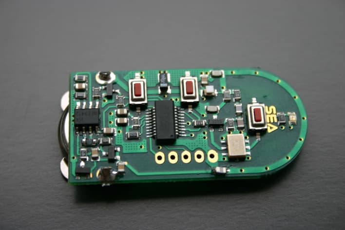
Click to zoom
Application Details
- Equipment Class
- DSC - Part 15 Security/Remote Control Transmitter
- Date of Grant
- May 20, 2007
- Application Purpose
- Original Equipment
- Date of Application
- May 20, 2007
- Equipment Note
- REMOTE CONTROL
- Frequency Range
- 433.92000000 - 433.92000000
- Company
- SEA USA Inc.
- Country
- United States
Documents & Files
Document Text
Text extracted from the exhibit documents filed with the FCC. Open a document above to read the original.
Users Manual
F.User’s manual E L I M N A R P R I Y SMART COPY TRANSMITTER TWO CHANNEL & THREE CHANNEL Freq. 433.920 MHz Rev. 00 , 09/2004 English DESTINATION OF USE The 433.920MHz SMART COPY transmitter has been planned to be used exclusively as a transmitter of digital data with a frequency of 433.920 MHz sent to a radio receiver created by SEA which transmits on the same frequency and which is codified to be interfaced with the 433.920 MHz SMART COPY transmitter. It must be used only as a generator of commands to send to a SEA s.r.l. receiver to automatize the opening and/or closing of doors, gates and leaves and it must be supplied with safety tension (3Vdc battery CR2032 size) which will be waste in the provided containers. Notice: The useful capacity of this system (as that of all the systems which operate with radio frequency), can change according to the entity of the electromagnetic pollution and of RF false signals in the installation site, or of probable obstacles which are bewteen the radio transmitter and the related receiver. Technical Characteristics Power Supply: 3Vdc (battery CR2032 size) Absorption: 20 mA max (in trasmission) Transmitting frequency :433.920MHz Capacity:100 mt Code: 64 bit digital N. of channels:2 3 Working temperature:-20°C / +55°C Storage temperature:-30°C / +80°C Dimensions:64 x 35 x 14 mm Humidity: from 5% to 90% not condensing DECLARATION OF CONFORMITY This transmitters is in conformity with the 99/5/EC directive based on the standards: - ETS EN 301 489; ETS EN 301 489-3; ETS EN 300 220-1; ETS EN 300 220-3; EN 60950 The user of this system must follow the norms in force in the country where it si used. Quoted from Part 2.1074 Devices subject only to a Declaration of Conformity shall be uniquely identified by the responsible party. This identification shall not be of a format which could be confused with the FCC identifier required on certified, notified, type accepted or type approved equipment. The responsible party shall maintain adequate identification records to facilitate positive identification for each device. Section 15.19 Labeling requirement This device complies with part 15 of the FCC Rules Operation is subject to the following two conditions: (1) This device may not cause harmful interference, and (2) this device must accept any interference received, including interference that may cause undesired operation. Section 15.21 Information to user. The users manual or instruction manual for an intentional or unintentional radiator shall caution the user that changes or modifications not expressly approved by the party responsible for compliance could void the user's authority to operate the equipment. In cases where the manual is provided only in a form other than paper, such as on a computer disk or over the Internet, the information required by this section may be included in the manual in that alternative form, provided the user can reasonably be expected to have the capability to access information in that form. NOTICE: THE MANUFACTURER CANNOT BE CONSIDERED RESPONSIBLE OF THE DAMAGES CAUSED BY PRODUCT MISUSE. SEA reserves the right to bring proper modifications or changes to its products and/or to this manual without warning. SERVICING The only servicing intervention to apply to this system is the battery substitution (see fig.1), when there is an extreme capacity reduction or when it stops working. To obtain optimum performance it is advisable to substitute the battery every two years. + - Fig. 1 Sistemi elettronici di Aperture Porte e Cancelli SEA S.r.l. DIREZIONE E STABILIMENTO: Zona industriale 64020 S.ATTO Teramo - (ITALY) Tel. 0861 588341 r.a. Fax 0861 588344 http://www.seateam.com e-mail:[email protected]
Block Diagram
C.Functional block diagram RF OUTPUT 433.920 MHz RF OUTPUT 433.920 MHz ENCODERENCODER KEY INPUTKEY INPUT POWER SUPPLY (BATTERY) POWER SUPPLY (BATTERY) RF INPUTRF INPUT
External Photos
B.Photographs Internal component sideInternal solder side External frontExternal back
ID Label/Location Info
A.FCC Label sample and sketch of location FCC ID:UCX-SMART Battery type CR2032 19.54 mm 8 1 9 m m .
Internal Photos
B.Photographs Internal component sideInternal solder side External frontExternal back
Operational Description
D.Operational description The transmitter uses, for its functioning, a codification section and a radio frequency transmission. The codification section consists of a microcontroller which, after an appropriate programming, creates a 66 bit code; such code will module the transmission frequency. The radio frequency section consists of a SAW resonator, which creates the 433,920 Mhz frequency carrier, a transistor and the appropriate filters (inductances and capacitors) which are essential to avoid spurious disturbances and harmonics.
Schematics
D.Schematic of unit S m a r t C o p y 4 3 3 . 9 2 0 M H z T r a n s m t t e r i
Test Report
1 FCC PART 15.231 TEST REPORT Applicant SEA USA INC. Address 8332 NW 30 TH Terrace Doral FL 33122 FCC ID UCX-SMART Product Description Remote Control Date Sample Received September 8, 2006 Date Tested September 12, 2006 Tested By Joe Scoglio Approved By Mario de Aranzeta Timco Report No. 1255ZUT6TestReport.PDF Test Results Pass Fail THE ATTACHED REPORT SHALL NOT BE REPRODUCED EXCEPT IN FULL WITHOUT THE WRITTEN APPROVAL OF TIMCO ENGINEERING, INC. 849 NW STATE ROAD 45 NEWBERRY, FL 32669 USA PH: 888.472.2424 OR 352.472.5500 FAX: 352.472.2030 EMAIL: [email protected] HTTP: //WWW.TIMCOENGR.COM Certificate # 0955-01 APPLICANT: SEA USA INC. FCC ID: UCXTX REPORT: V:\S\SEA USA\1255ZUT6\1255ZUT6TestReport.doc Page 2 of 12 TABLE OF CONTENTS ATTESTATION STATEMENT....................................................................................... 3 GENERAL INFORMATION .......................................................................................... 4 EMC EQUIPMENT LIST ............................................................................................. 5 TEST PROCEDURE ................................................................................................... 6 RADIATION INTERFERENCE ..................................................................................... 7 CALCULATION OF DUTY CYCLE ............................................................................... 9 OCCUPIED BANDWIDTH ......................................................................................... 12 APPLICANT: SEA USA INC. FCC ID: UCX-SMART REPORT: V:\S\SEA USA\1255ZUT6\1255ZUT6TestReport.doc Page 3 of 12 ATTESTATION STATEMENT This equipment has been tested in accordance with the standards identified in the referenced test report. To the best of my knowledge and belief, these tests were performed using the measurement procedures described in this report. All instrumentation and accessories used to test products for compliance to the indicated standards are calibrated regularly in accordance with ISO 17025 requirements. I attest that the necessary measurements were made by me or under my supervision, at Timco Engineering, Inc. located at 849 N.W. State Road 45, Newberry, Florida 32669 USA. Authorized by: Mario de Aranzeta Signature: On file Function: Engineer Date: September 13, 2006 Certificate # 0955-01 APPLICANT: SEA USA INC. FCC ID: UCX-SMART REPORT: V:\S\SEA USA\1255ZUT6\1255ZUT6TestReport.doc Page 4 of 12 GENERAL INFORMATION Applicable Rule(s): FCC Part 15.231, ANSI C63.4 DUT Specification Description Remote Control Transmitter FCC ID UCX-SMART Model Name N/A Tx Frequency 433.92MHz 110–120Vac/50– 60Hz DC Power Power Source Battery Operated Exclusively Test Item Prototype Pre- Production Production Type of Equipment Fixed Mobile Portable Test Facility: The test sites are located at Timco Engineering Inc., 849 NW State Road 45 Newberry, FL 32669 USA. Test Condition: The temperature was 26ºC with a relative humidity of 50%. Modification to the DUT: No modification was made to the DUT during testing. Deviation from the standard: No deviation. Test Exercise (e.g software description, test signal, etc.): The DUT was placed in continuous transmit mode of operation. APPLICANT: SEA USA INC. FCC ID: UCX-SMART REPORT: V:\S\SEA USA\1255ZUT6\1255ZUT6TestReport.doc Page 5 of 12 EMC EQUIPMENT LIST Device Manufacturer Model Serial Number Cal/Char Date Due Date 3-Meter OATS TEI N/A N/A Listed 1/11/06 1/10/09 3/10-Meter OATS TEI N/A N/A Listed 3/27/04 3/26/07 Analyzer Tan Tower Spectrum Analyzer HP 8566B Opt 462 3138A07786 3144A20661 CAL 12/7/05 12/7/07 Analyzer Tan Tower RF Preselector HP 85685A 3221A01400 CAL 12/7/05 12/7/07 Analyzer Tan Tower Quasi- Peak Adapter HP 85650A 3303A01690 CAL 12/8/05 12/8/07 Analyzer Tan Tower Preamplifier HP 8449B- H02 3008A00372 CAL 12/8/05 12/8/07 Analyzer Blue Tower Spectrum Analyzer HP 8568B 2928A04729 2848A18049 CAL 4/13/05 4/13/07 Analyzer Blue Tower RF Preselector HP 85685A 2926A00983 CAL 9/5/05 9/5/07 Analyzer Blue Tower Quasi- Peak Adapter HP 85650A 2811A01279 CAL 4/13/05 4/13/07 Analyzer Silver Tower Spectrum Analyzer HP 8566B Opt 462 3552A22064 3638A08608 CAL 12/8/04 12/8/06 Analyzer Silver Tower RF Preselector HP 85685A 2620A00294 CAL 4/27/04 12/8/06 Analyzer Silver Tower Quasi- Peak Adapter HP 85650A 3303A01844 CAL 12/8/04 12/8/06 Analyzer Open- Frame Tower Preamplifier HP 8449B 3008A01075 CAL 8/8/05 8/8/07 Antenna: Biconnical Electro- Metrics BIA-25 1171 CAL 4/29/05 4/29/07 Antenna: Biconnical Eaton 94455-1 1057 CAL 12/12/05 12/12/07 APPLICANT: SEA USA INC. FCC ID: UCX-SMART REPORT: V:\S\SEA USA\1255ZUT6\1255ZUT6TestReport.doc Page 6 of 12 TEST PROCEDURE Radiation Interference: The test procedure used was ANSI C63.4-2003 using a Agilent spectrum analyzer with a preselector. The bandwidth of the spectrum analyzer was 100 kHz with an appropriate sweep speed. The analyzer was calibrated in dB above a microvolt at the output of the antenna. The resolution bandwidth was 100 kHz and the video bandwidth was 300 kHz. Occupied Bandwidth: A small sample of the transmitter output was fed into the spectrum analyzer and the following plot was generated. The vertical scale is set to 10 dB per division. Formula Of Conversion Factors: The Field Strength at 3m was established by adding the meter reading of the spectrum analyzer (which is set to read in units of dBuV) to the antenna correction factor supplied by the antenna manufacturer. The antenna correction factors are stated in terms of dB. The gain of the Preselector was accounted for in the Spectrum Analyzer Meter Reading. Example: Freq (MHz) METER READING + ACF +CL= FS 33 20 dBuV + 10.36 dB/m+1.2 = 31.56 dBuV/m @ 3m ANSI C63.4-2003 Measurement Procedures: The DUT was placed on a table 80 cm high and with dimensions of 1m by 1.5m. The UUT was placed in the center of the table. The table used for radiated measurements is capable of continuous rotation. The spectrum was scanned from 30 MHz to 10th harmonic of the fu…
Text truncated - open the document above for the full version.
Contact Information
Applicant
Fabrizio Di Saverio(President)
Test Firm
Timco Engineering, Inc.Sid Sanders
Technical Specifications
| # | Rule Parts | Frequency Range | Power Output |
|---|---|---|---|
| 1 | 15.231 | 433.92 MHz - 433.92 MHz | - |