UDB31539Wireless Footswitch
IRIDEX Corporation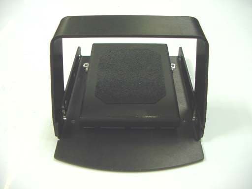
Click to zoom
Application Details
- Equipment Class
- DXT - Part 15 Low Power Transceiver, Rx Verified
- Date of Grant
- Aug 09, 2006
- Application Purpose
- Original Equipment
- Date of Application
- Aug 09, 2006
- Equipment Note
- Wireless Footswitch
- Frequency Range
- 2414.00000000 - 2456.00000000
- Company
- IRIDEX Corporation
- Country
- United States
Documents & Files
Document Text
Text extracted from the exhibit documents filed with the FCC. Open a document above to read the original.
Users Manual
Premarket Notification, 510(k) Submission for: Section 13: Proposed Labeling – Page 1-1 IRIDEX Wireless Footswitch IRIDEX Wireless Footswitch Operator Instructions IRIDEX Laser consoles can be operated with either a wired Footswitch or wireless Footswitch/Receiver pair. The wireless Receiver or wired Footswitch is connected to the Footswitch IN jack on the rear of the laser console. The system always tests for a properly connected wireless Receiver or wired Footswitch in the released state before entering Treat mode. If you try to select Treat mode when the wireless Receiver or wired Footswitch is damaged or improperly connected, the Status Display on the console will display the message “Connect Footswitch.” If you try to enter Treat mode with the Footswitch depressed or depress the Footswitch while the green Treat light is still flashing on entry to Treat mode, the Status Display will display the message “Release Footswitch”. Note: Each Footswitch/receiver pair is uniquely linked and will not work with other IRIDEX Footswitches or similar components. Make sure to clearly identify each pair to prevent separation of the linked components. Changes to internal components may result in increased emissions or decreased immunity. The wireless device is made up of two parts: a battery powered Footswitch and a console- powered receiver. The Footswitch has LEDs to assist in trouble shooting and to indicate battery conditions. The LEDs provide status as follows: Footswitch LED indicators Footswitch LED Display Status Green Flash following pedal depression Footswitch OK, Batteries OK Amber Flash following pedal depression Footswitch OK, Batteries Low Blink Red LED for 10 seconds following footswitch release No RF Communication - The console only provides power to the receiver when in “treat” mode. - When the Footswitch is activated the Footswitch processor initiates a communication link with the receiver. - The Footswitch is designed to operate within a minimum of 15 feet of the console. - Each Footswitch and receiver pair is uniquely linked in order to prevent any other Footswitch from activating the laser console. - The Footswitch is designed to maximize battery life. In the unlikely event that the batteries need to be replaced, please contact your sales representative or IRIDEX Customer Service for a replacement. To install, connect the receiver to “Footswitch IN” located on the rear of the laser console. Premarket Notification, 510(k) Submission for: Section 13: Proposed Labeling – Page 1-2 IRIDEX Wireless Footswitch Inspecting and Cleaning the IRIDEX Wireless Footswitch The IRIDEX Wireless Footswitch ) is submersible (IPX8 IEC529). The wireless receiver is NOT submersible. To decontaminate and disinfect the Footswitch: 1. Using water, isopropyl alcohol, or enzymatic detergents with mild pH such as ENZOL, remove all traces of blood and other body fluids from all exposed surfaces of the Footswitch assembly. 2. Immerse the Footswitch in a CIDEX (2.4% glutaraldehyde) solution to achieve the desired level of disinfection: a minimum of 45 minutes at 25ºC to achieve a high level of disinfection, or a minimum of 10 minutes at 20ºC to 25ºC to achieve an intermediate level of disinfection. 3. Remove the Footswitch from the CIDEX solution. 4. Stand the Footswitch on end to drain all fluids. 5. Immerse the Footswitch in a large amount of water for a minimum of 1 minute. Repeat this step two or more times using clean water for each rinse. 6. Stand the Footswitch on end. 7. Allow the Footswitch to air-dry completely before reusing. Premarket Notification, 510(k) Submission for: Section 13: Proposed Labeling – Page 1-3 IRIDEX Wireless Footswitch Wireless Footswitch Safety Information Electromagnetic Interference IRIDEX lasers and accessories (including the Wireless Footswitch) have been tested and found to comply with the limits for medical devices in IEC 60601-1-2. These limits are designed to provide reasonable protection against harmful interference in a typical medical installation. The laser console and accessories generate, use and can radiate radio-frequency energy and, if not installed and used in accordance with the instructions, may cause harmful interference to other devices in the vicinity. There is no guarantee that interference will not occur in a particular installation. If the laser and/or footswitch does cause harmful interference to other devices, which can be determined by turning the system off and on, the user is encouraged to try to correct the interference by one or more of the following measures: - Reorient or relocate the receiving device. - Increase the separation between the equipment. - Connect the laser console into an outlet on a circuit different from that to which the other device(s) are connected. - Consult IRIDEX Customer Service for help. This device complies with part 15 of the FCC Rules. Operation is subject to the following two conditions: (1) This device may not cause harmful interference, and (2) this device must accept any interference received, including interference that may cause undesired operation. This device complies with Part 15 of the FCC Rules. Operation is subject to the following two conditions: (1) this device may not cause harmful interference, and (2) this device must accept any interference received, including interference that may cause undesired operation. This Class B digital apparatus meets all requirements of the Canadian Interference-Causing Equipment Regulations. Cet appareil numérique de la classe B respecte toutes les exigences du Réglement sur le matériel brouilleur du Canada. • CAUTION: Changes or modifications not expressly approved by the party responsible for compliance could void the user’s authority to operate the equipment. Note: MEDICAL ELECTRICAL EQUIPMENT needs special precautions regarding EMC and needs to be installed and put into service according to the EMC information provided in this manual.” Note: “Portable and mobile …
Text truncated - open the document above for the full version.
External Photos
Footswitch and Receiver External pictures Footswitch External pictures Footswitch External pictures Footswitch External pictures Receiver External pictures
ID Label/Location Info
IPX8 LABEL P/N 31540-1A UBD31539 6590A-31539 IC ID: S/N: 100001F P/N: 31539 LABEL, WIRELESS FOOTSWITCHPN 31540 REV A FCC ID: MATERIAL: .010 8B35ADHESIVE: 3M 468 BACKGROUND TO BE BLACKWHITE LETTERSBLUE IS PMS 285C R 0.139in x 4 1.25” 3.00” LABEL P/N 31540-2A UBD31539 6590A-31539 IC ID: S/N: 100001R P/N: 31539 FCC ID: 1.50” 1.875” SERIAL NUMBERS FOR EACH PAIR OF LABELS MUST BE IDENTICAL WITH THE EXCEPTION OF THE LETTER SUFFIX. INCREASE SERIAL NUMBER INCREMENTALLYSTARTING WITH 100001DO NOT DUPLICATE SERIAL NUMBERS
Internal Photos
Footswitch Internal pictures Footswitch Internal pictures Footswitch Internal pictures Footswitch Internal pictures Footswitch Internal pictures Footswitch Internal pictures Footswitch Internal pictures Receiver Internal pictures Receiver Internal pictures Receiver Internal pictures Receiver Internal pictures Receiver Internal pictures
Test Report
EMC Report for Iridex on the models: Footswitch and Receiver: File: 3099352MPK-001 Page 1 of 23 TEST REPORT Report Number: 3099352MPK-001 Project Number: 3099352 May 31, 2006 Testing performed on the Wireless Footswitch Models: Footswitch and Receiver FCC ID: UBD31539 IC ID: 6590A-31539 to FCC Part 15.249 RSS-210, Annex 2.9 For IRIDEX Corporation A2LA Certificate Number: 1755-01 Test Performed by: Test Authorized by: Intertek Testing Services NA, Inc 1365 Adams Court Menlo Park, CA 94025 Iridex 1212 Terra Bella Ave. Mountain View, CA 94043 Prepared by: Date: May 31, 2006 Krishna K Vemuri Reviewed by: Date: May 31, 2006 David Chernomordik, EMC Technical Manager This report is for the exclusive use of Intertek's Client and is provided pursuant to the agreement between Intertek and its Client. Intertek's responsibility and liability are limited to the terms and conditions of the agreement. Intertek assumes no liability to any party, other than to the Client in accordance with the agreement, for any loss, expense or damage occasioned by the use of this report. Only the Client is authorized to copy or distribute this report and then only in its entirety. Any use of the Intertek name or one of its marks for the sale or advertisement of the tested material, product or service must first be approved in writing by Intertek. The observations and test results in this report are relevant only to the sample tested. This report by itself does not imply that the material, product, or service is or has ever been under an Intertek certification program. This report must not be used to claim product endorsement by A2LA, NIST nor any other agency of the U.S. Government. EMC Report for Iridex on the models: Footswitch and Receiver: File: 3099352MPK-001 Page 2 of 23 TABLE OF CONTENTS 1.0 Summary of Tests.........................................................................................................................3 2.0 General Description......................................................................................................................4 2.1 Product Description...........................................................................................................4 2.2 Related Submittal(s) Grants...............................................................................................5 2.3 Test Methodology..............................................................................................................5 2.4 Test Facility.......................................................................................................................5 3.0 System Test Configuration ..........................................................................................................6 3.1 Support Equipment and description ..................................................................................6 3.2 Block Diagram of Test Setup ............................................................................................6 3.3 Justification .......................................................................................................................7 3.4 Software Exercise Program ...............................................................................................7 3.5 Mode of operation during test............................................................................................7 3.6 Modifications required for Compliance.............................................................................7 3.7 Additions, deviations and exclusions from standards........................................................7 4.0 Measurement Results ...................................................................................................................8 4.1 Transmitter Radiated Emissions........................................................................................8 4.2 Out of Band Emission Plots.............................................................................................12 4.3 Occupied Bandwidth.......................................................................................................19 4.4 Frequency Stability..........................................................................................................20 5.0 Antenna Requirement................................................................................................................21 6.0 List of test equipment.................................................................................................................22 7.0 Document History.......................................................................................................................23 EMC Report for Iridex on the models: Footswitch and Receiver: File: 3099352MPK-001 Page 3 of 23 1.0 Summary of Tests TEST REFERENCE FCC Part 15C REFERENCE IC RSS-210/ RSS-Gen RESULT Field Strength of Fundamental 15.249a A2.9(1) RSS-210 Complies Field Strength of Harmonics 15.249a A2.9(1) RSS-210 Complies Radiated Emissions outside the band 15.249c A2.9(2) RSS-210 Complies Line Conducted Emissions 15.207 7.2.2 RSS-Gen Not Applicable * Occupied Bandwidth - 4.4.1 RSS-Gen 738KFXD ** Frequency Stability - 7.2.4 RSS-Gen 5.3 ppm ** Antenna requirement 15.203 7.1.4 RSS-Gen Complies * The device is battery powered. ** No limit is specified in the Standard EMC Report for Iridex on the models: Footswitch and Receiver: File: 3099352MPK-001 Page 4 of 23 2.0 General Description 2.1 Product Description The Wireless Footswitch devices are intended for use with IRIDEX Laser Systems. It consists of a Footswitch transceiver and a Receiver which is also transceiver. Both transceivers have identical electronic components, but different antennas and different housings. In normal operation, the Footswitch radio transmits data (80 bits) every time when the footswitch is pressed. The receiver receives the signal and transmit an acknowledge signal and goes to receive mode until the footswitch is pressed again.…
Text truncated - open the document above for the full version.
Contact Information
Applicant
John Arthur Jossy(Director of RA/QA)
Technical Contact
Intertek Testing ServicesDavid Chernomordik
[email protected]650-463-2900
1365 Adams Ct · Menlo Park, California · United States
Test Firm
Intertek Testing Services NA Inc.John Quigley
Technical Specifications
| # | Rule Parts | Frequency Range | Power Output | Tolerance |
|---|---|---|---|---|
| 1 | 15C | 2.41 GHz - 2.46 GHz | - | 0.0010000000 ppm |