UDX-60014010Wireless 802.11 abgn AP
Cisco Systems, Inc.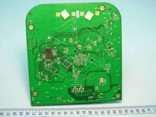
Click to zoom
Application Details
- Equipment Class
- DTS - Digital Transmission System
- Date of Grant
- Mar 27, 2011
- Application Purpose
- Original Equipment
- Date of Application
- Mar 27, 2011
- Equipment Note
- Wireless 802.11 abgn AP
- Frequency Range
- 5745.00000000 - 5825.00000000
- Company
- Cisco Systems, Inc.
- Country
- United States
Documents & Files
Document Text
Text extracted from the exhibit documents filed with the FCC. Open a document above to read the original.
Users Manual
Meraki MR24 Hardware Installation Guide Trademarks Meraki, Meraki MR24, Meraki Cloud Controller, and Meraki Mesh are trademarks of Meraki, Inc. Other brand and product names are registered trademarks or trademarks of their respective holders. Statement of Conditions In the interest of improving internal design, operational function, and/or reliability, Meraki reserves the right to make changes to the products described in this document without notice. Meraki does not assume any liability that may occur due to the use or application of the product(s) or circult layout(s) described herein. Warranty Meraki, Inc. provides a lifetime warranty on this product. Warranty details may be found at www.meraki.com/legal. 3 Table of Contents 1 Scope of Document and Related Publications 4 2 MR24 Overview 5 2.1 Package Contents 5 2.2 Understanding the MR24 5 2.3 Security Features 7 2.4 Ethernet Ports 7 2.5 Power Source Options 7 2.6 Factory Reset Button 7 2.7 LED Indicators and Run Dark Mode 7 2.8 UL 2043 Plenum rating 8 3 Pre-Install Preparation 8 3.1 Configure Your Network in Dashboard 8 3.2 Check and Upgrade Firmware 8 3.3 Check and Configure Firewall Settings 8 3.4 Assigning IP Addresses to MR24s 9 3.4.1 Dynamic Assignment 9 3.4.2 Static Assignment 9 3.4.3 Static IP Assignment via DHCP Reservations 9 3.5 Collect Tools 10 3.6 Collect Additional Hardware for Installation 10 4 Installation Instructions 11 4.1 Choose Your Mounting Location 11 4.2 Install the MR24 11 4.2.1 Attach the Mount Plate 11 4.2.1.1 Wall or Solid Ceiling Mount Using Mount Plate 13 4.2.1.2 Drop Ceiling Mount Using Mount Plate 14 4.2.1.3 Electrical Junction Box Mount Using Mount Plate 18 4.2.1.4 Plenum Mount (Above Drop Ceiling) 19 4.2.2 Power the MR24 20 4.2.2.1 Powering the MR24 with Meraki AC Adapter 21 4.2.2.2 Powering the MR24 with Meraki 802.3af Power over Ethernet Injector 21 4.2.2.3 Powering the MR24 with an 802.3af Power over Ethernet Switch 22 4.2.3 Mount the MR24 22 4.2.3.1 Assemble Security Hasp to the MR24 22 4.2.3.2 Assemble MR24 to the Mount Plate 23 4.2.3.3 Desk or Shelf Mount 25 4.2.3.4 Wall or Solid Ceiling Mount without Mount Plate 25 4.3 Secure the MR24 26 4.3.1 Security Screw 26 4.3.2 Pad Lock 26 4.3.2 Kensington Lock 26 4.4 Verify Device Functionality and Test Network Coverage 27 5 Troubleshooting 27 6 Regulatory Information for MR24 28 4 1 Scope of Document and Related Publications The MR24 Hardware Installation Guide describes the installation procedure for the MR24 access point. Additional reference documents are available online at www.meraki.com/library/product. 5 MR24 access pointDrop ceiling mounting kit 2 MR24 Overview The Meraki MR24 is an enterprise-class, dual-concurrent 3x3 MIMO 802.11n access point designed for high- density deployments in offices, schools, hospitals and hotels. When connected to the Meraki Cloud Controller, the MR24 enables the creation of ultra-high speed, reliable indoor wireless networks quickly, easily and cost- effectively. 2.1 Package Contents The MR24 package contains the following: 2.2 Understanding the MR24 Your Meraki MR24 has the following features: Kensington lock hard point Spare hardware kitSecurity hasp kitSecurity screws Wall screws & anchors LED indicators Mounting Template Mounting plate 6 Cable slot Security tab Your MR24 mount plate has the following features: MR24 cable access bay Mount plate attachment slots (2x) Access point mounting posts (2x) Desk mount feet (4x) Cable routing slot Cable access bay AC Adapter plug Ethernet 0 port (10/100/1000) Factory Reset Button Various mounting holes (see p. 13-14 for details) AP alignment features 7 2.3 Security Features The MR24 features multiple options for physically securing the access point after installation: 1. Security screw – The accessory kit includes screws that can be used to secure the access point to the mount plate. Engaging the security screw prevents accidental dislodging and theft. 2. Kensington lock – The access point contains a hard point that allows it to be secured to any nearby permanent structure using a standard Kensington lock. 2.4 Ethernet Ports Both MR24 and MR24 feature a Gigabit Ethernet RJ45 port that accepts 802.3af power (labeled “Eth0, PoE”). This port should be used for uplink to your WAN connection. 2.5 Power Source Options The MR24 access point can be powered using either the Meraki AC Adapter or 802.3af PoE Injector (both sold separately) or a third-party 802.3af PoE switch. 2.6 Factory Reset Button If the button is pressed and held for at least five seconds and then released, the MR24 will reboot and be restored to its original factory settings by deleting all configuration information stored on the unit. 2.7 LED Indicators and Run Dark Mode Your MR24 is equipped with a series of LED lights on the front of the unit to convey information about system functionality and performance. The MR24 may be operated in “Run Dark” mode for additional security and to reduce the visibility of the access point. In this mode, the LEDs will not be illuminated. This mode may be enabled through Meraki Dashboard. Signal Strength One Light: Fair Four Lights: Strongest Moving Lights: Searching for signal Flashing Lights: Error state. May indicate bad gateway or other routing fault Radio Power Off: MR24 is off Solid Orange: MR24 is booting or trying to find a path to the internet Solid Green: MR24 is fully operational and connected to the network Flashing Orange: Firmware is upgrading Flashing Green: Error state. May indicate bad gateway or other routing fault Ethernet Off: No active network connection at the Ethernet port On: Active network connection at the Ethernet port Flashing: Error state. May indicate bad gateway or other routing fault 8 2.8 UL 2043 Plenum rating The MR24 meets the UL 2043 plenum-rating standard. This certifies that the MR24 has adequate fire resistance and low smoke-emission characteristics to be mounted and operated in a building’s environmental air spaces, such as above suspend…
Text truncated - open the document above for the full version.
External Photos
Page 1 CONSTRUCTION PHOTOS OF EUT
Internal Photos
Page 2 Page 3 Page 4 Page 5 Page 6 Page 7 Page 8 Page 9 Page 10 Page 11 Page 12
Operational Description
FCC ID: UDX-60014010 Report No.: RF110219C05 Operational Description This device is a Wireless 802.11 abgn AP, which operates in both of the 5GHz and 2.4GHz bands and can transmitting simultaneously, the maximum data rate could be up to 300Mbps which OFDM technique. If the signal to noise radio is too poor which could not support 300Mbps, the 11Mbps data rate with DSSS technique will be applied. The transmitter of the EUT is powered by an adapter or the POE. The antennas are internal PIFA antennas with IPEX antenna connectors. The other instruction, please have a look at the users manual. FCC 15.407(c) states: The device shall automatically discontinue transmission in case of either absence of information to transmit or operational failure. These provisions are not intended to preclude the transmission of control or signaling information or the use of repetitive codes used by certain digital technologies to complete frame or burst intervals. Applicants shall include in their application for equipment authorization a description of how this requirement is met” Data transmission is always initiated by software, which is then pass down through the MAC, through the digital and analog baseband, and finally to the RF chip. Several special packets (ACKs, CTS, PSPoll, etc...) are initiated by the MAC. There are the only ways the digital baseband portion will turn on the RF transmitter, which it then turns off at the end of the packet. Therefore, the transmitter will be on only while one of the aforementioned packets are being transmitted.
RF Exposure Info
Report No.: SA110219C05 Report Format Version 4.0.0 1 RF EXPOSURE REPORT REPORT NO.: SA110219C05 MODEL NO.: MR24 FCC ID: UDX-60014010 ACCORDING: FCC Guidelines for Human Exposure IEEE C95.1 APPLICANT: Meraki Inc. ADDRESS: 660 Alabama St, 4th floor, San Francisco, CA 94110 ISSUED BY: Bureau Veritas Consumer Products Services (H.K.) Ltd., Taoyuan Branch LAB ADDRESS: No. 47, 14th Ling, Chia Pau Tsuen, Lin Kou Hsiang, Taipei Hsien 244, Taiwan, R.O.C. TEST LOCATION: No. 19, Hwa Ya 2nd Rd, Wen Hwa Tsuen, Kwei Shan Hsiang, Taoyuan Hsien 333, Taiwan, R.O.C. Report No.: SA110219C05 Report Format Version 4.0.0 2 RELEASE CONTROL RECORD ISSUE NO. REASON FOR CHANGE DATE ISSUED Original release N/A Mar. 09, 2011 Report No.: SA110219C05 Report Format Version 4.0.0 3 1. RF EXPOSURE LIMIT LIMITS FOR MAXIMUM PERMISSIBLE EXPOSURE (MPE) FREQUENCY RANGE (MHz) ELECTRIC FIELD STRENGTH (V/m) MAGNETIC FIELD STRENGTH (A/m) POWER DENSITY (mW/cm 2 ) AVERAGE TIME (minutes) LIMITS FOR GENERAL POPULATION / UNCONTROLLED EXPOSURE 300-1500 ... ... F/1500 30 1500-100,000 ... ... 1.0 30 F = Frequency in MHz 2. MPE CALCULATION FORMULA Pd = (Pout*G) / (4*pi*r2) where Pd = power density in mW/cm2 Pout = output power to antenna in mW G = gain of antenna in linear scale Pi = 3.1416 R = distance between observation point and center of the radiator in cm 3. CLASSIFICATION The antenna of this product, under normal use condition, is at least 25cm away from the body of the user. So, this device is classified as Mobile Device. Report No.: SA110219C05 Report Format Version 4.0.0 4 4. CALCULATION RESULT OF MAXIMUM CONDUCTED POWER MODULATION MODE FREQUENCY BAND (MHz) MAX CONDUCTED POWER (dBm) ANTENNA GAIN (dBi) DISTANCE (cm) POWER DENSITY (mW/cm 2 ) LIMIT (mW/cm 2 ) 802.11b 2412-2462 25.8 9.8 25 0.463 1 802.11g 2412-2462 26.0 9.8 25 0.484 1 802.11n (20MHz) 2412-2462 29.1 5 25 0.327 1 802.11n (40MHz) 2422-2452 26.9 5 25 0.197 1 802.11a 5180-5240 12.2 10.8 25 0.028 1 802.11n (20MHz) 5180-5240 16.8 6 25 0.024 1 802.11n (40MHz) 5180-5240 16.8 6 25 0.024 1 802.11a 5745-5825 25.0 10.8 25 0.484 1 802.11n (20MHz) 5745-5825 26.1 6 25 0.207 1 802.11n (40MHz) 5745-5825 26.5 6 25 0.227 1 NOTE: (802.11 b/g): Directional gain =5dBi+10log(3)=9.8dBi (802.11 a): Directional gain = 6dBi+10log(3)=10.8dBi CONCULSION: Both of the WLAN 2.4G & 5.0G can transmit simultaneously, the formula of calculated the MPE is: CPD1 / LPD1 + CPD2 / LPD2 + ......etc. < 1 CPD = Calculation power density LPD = Limit of power density WLAN 2.4G + WLAN 5.0G = 0.484 + 0.484 = 0.968 Therefore, the maximum calculation of this situation is 0.968, which is less than the “1” limit.
Test Report
Report No.: RF110219C05 1 Report Format Version 4.0.0 FCC TEST REPORT (15.247) REPORT NO.: RF110219C05 MODEL NO.: MR24 FCC ID: UDX-60014010 RECEIVED: Jan. 21, 2011 TESTED: Jan. 21 ~ Mar. 08, 2011 ISSUED: Mar. 09, 2011 APPLICANT: Meraki Inc. ADDRESS: 660 Alabama St, 4th floor, San Francisco, CA 94110 ISSUED BY: Bureau Veritas Consumer Products Services (H.K.) Ltd., Taoyuan Branch LAB ADDRESS: No. 47, 14th Ling, Chia Pau Tsuen, Lin Kou Hsiang, Taipei Hsien 244, Taiwan, R.O.C. TEST LOCATION: No. 19, Hwa Ya 2nd Rd, Wen Hwa Tsuen, Kwei Shan Hsiang, Taoyuan Hsien 333, Taiwan, R.O.C. This test report consists of 123 pages in total. It may be duplicated completely for legal use with the approval of the applicant. It should not be reproduced except in full, without the written approval of our laboratory. The client should not use it to claim product certification, approval or endorsement by TAF or any government agency. The test results in the report only apply to the tested sample. Report No.: RF110219C05 2 Report Format Version 4.0.0 TABLE OF CONTENTS RELEASE CONTROL RECORD.............................................................................................. 5 1. CERTIFICATION........................................................................................................... 6 2. SUMMARY OF TEST RESULTS .................................................................................. 7 2.1 MEASUREMENT UNCERTAINTY ............................................................................... 7 3. GENERAL INFORMATION ........................................................................................... 8 3.1 GENERAL DESCRIPTION OF EUT ............................................................................. 8 3.2 DESCRIPTION OF TEST MODES ............................................................................. 10 3.2.1 CONFIGURATION OF SYSTEM UNDER TEST ........................................................ 11 3.2.2 TEST MODE APPLICABILITY AND TESTED CHANNEL DETAIL ............................. 12 3.3 GENERAL DESCRIPTION OF APPLIED STANDARDS ............................................ 16 3.4 DESCRIPTION OF SUPPORT UNITS ....................................................................... 16 4. TEST TYPES AND RESULTS (FOR 2.4GHz BAND)................................................. 17 4.1 RADIATED EMISSION MEASUREMENT .................................................................. 17 4.1.1 LIMITS OF RADIATED EMISSION MEASUREMENT................................................ 17 4.1.2 TEST INSTRUMENTS................................................................................................ 18 4.1.3 TEST PROCEDURES ................................................................................................ 19 4.1.4 DEVIATION FROM TEST STANDARD....................................................................... 19 4.1.5 TEST SETUP.............................................................................................................. 20 4.1.6 EUT OPERATING CONDITIONS ............................................................................... 20 4.1.7 TEST RESULTS ......................................................................................................... 21 4.2 CONDUCTED EMISSION MEASUREMENT ............................................................. 35 4.2.1 LIMITS OF CONDUCTED EMISSION MEASUREMENT........................................... 35 4.2.2 TEST INSTRUMENTS................................................................................................ 35 4.2.3 TEST PROCEDURES ................................................................................................ 36 4.2.4 DEVIATION FROM TEST STANDARD....................................................................... 36 4.2.5 TEST SETUP.............................................................................................................. 37 4.2.6 EUT OPERATING CONDITIONS ............................................................................... 37 4.2.7 TEST RESULTS ......................................................................................................... 38 4.3 6dB BANDWIDTH MEASUREMENT.......................................................................... 42 4.3.1 LIMITS OF 6dB BANDWIDTH MEASUREMENT ....................................................... 42 4.3.2 TEST INSTRUMENTS................................................................................................ 42 4.3.3 TEST PROCEDURE................................................................................................... 42 4.3.4 DEVIATION FROM TEST STANDARD....................................................................... 42 4.3.5 TEST SETUP.............................................................................................................. 43 4.3.6 EUT OPERATING CONDITIONS ............................................................................... 43 4.3.7 TEST RESULTS ......................................................................................................... 44 4.4 MAXIMUM OUTPUT POWER .................................................................................... 48 4.4.1 LIMITS OF MAXIMUM OUTPUT POWER MEASUREMENT..................................... 48 4.4.2 INSTRUMENTS .......................................................................................................... 48 4.4.3 TEST PROCEDURES ................................................................................................ 48 4.4.4 DEVIATION FROM TEST STANDARD....................................................................... 49 4.4.5 TEST SETUP.............................................................................................................. 49 4.4.6 EUT OPERATING CONDITIONS ............................................................................... 49 4.4.7 TEST RESULTS ............................................…
Text truncated - open the document above for the full version.
Test Report
Report No.: RF110219C05-1 1 Report Format Version 4.0.0 FCC TEST REPORT (15.407) REPORT NO.: RF110219C05-1 MODEL NO.: MR24 FCC ID: UDX-60014010 RECEIVED: Jan. 21, 2011 TESTED: Jan. 21 ~ Mar. 08, 2011 ISSUED: Mar. 09, 2011 APPLICANT: Meraki Inc. ADDRESS: 660 Alabama St, 4th floor, San Francisco, CA 94110 ISSUED BY: Bureau Veritas Consumer Products Services (H.K.) Ltd., Taoyuan Branch LAB ADDRESS: No. 47, 14th Ling, Chia Pau Tsuen, Lin Kou Hsiang, Taipei Hsien 244, Taiwan, R.O.C. TEST LOCATION: No. 19, Hwa Ya 2nd Rd, Wen Hwa Tsuen, Kwei Shan Hsiang, Taoyuan Hsien 333, Taiwan, R.O.C. This test report consists of 72 pages in total. It may be duplicated completely for legal use with the approval of the applicant. It should not be reproduced except in full, without the written approval of our laboratory. The client should not use it to claim product certification, approval or endorsement by TAF or any government agency. The test results in the report only apply to the tested sample. Report No.: RF110219C05-1 2 Report Format Version 4.0.0 TABLE OF CONTENTS RELEASE CONTROL RECORD.............................................................................................. 4 1. CERTIFICATION........................................................................................................... 5 2. SUMMARY OF TEST RESULTS .................................................................................. 6 2.1 MEASUREMENT UNCERTAINTY................................................................................ 6 3. GENERAL INFORMATION ........................................................................................... 7 3.1 GENERAL DESCRIPTION OF EUT ............................................................................. 7 3.2 DESCRIPTION OF TEST MODES ............................................................................... 8 3.2.1 CONFIGURATION OF SYSTEM UNDER TEST .......................................................... 9 3.2.2 TEST MODE APPLICABILITY AND TESTED CHANNEL DETAIL ............................. 10 3.3 GENERAL DESCRIPTION OF APPLIED STANDARDS ............................................ 12 3.4 DESCRIPTION OF SUPPORT UNITS ....................................................................... 12 4. TEST TYPES AND RESULTS .................................................................................... 13 4.1 RADIATED EMISSION MEASUREMENT .................................................................. 13 4.1.1 LIMITS OF RADIATED EMISSION MEASUREMENT................................................ 13 4.1.2 LIMITS OF UNWANTED EMISSION OUT OF THE RESTRICTED BANDS .............. 13 4.1.3 TEST INSTRUMENTS................................................................................................ 14 4.1.4 TEST PROCEDURES ................................................................................................ 15 4.1.5 DEVIATION FROM TEST STANDARD....................................................................... 15 4.1.6 TEST SETUP.............................................................................................................. 16 4.1.7 EUT OPERATING CONDITION.................................................................................. 16 4.1.8 TEST RESULTS ......................................................................................................... 17 4.2 CONDUCTED EMISSION MEASUREMENT ............................................................. 27 4.2.1 LIMITS OF CONDUCTED EMISSION MEASUREMENT........................................... 27 4.2.2 TEST INSTRUMENTS................................................................................................ 27 4.2.3 TEST PROCEDURES ................................................................................................ 28 4.2.4 DEVIATION FROM TEST STANDARD....................................................................... 28 4.2.5 TEST SETUP.............................................................................................................. 29 4.2.6 EUT OPERATING CONDITIONS ............................................................................... 29 4.2.7 TEST RESULTS ......................................................................................................... 30 4.3 PEAK TRANSMIT POWER MEASUREMENT ........................................................... 34 4.3.1 LIMITS OF PEAK TRANSMIT POWER MEASUREMENT ......................................... 34 4.3.2 TEST INSTRUMENTS................................................................................................ 34 4.3.3 TEST PROCEDURE................................................................................................... 35 4.3.4 DEVIATION FROM TEST STANDARD....................................................................... 35 4.3.5 TEST SETUP.............................................................................................................. 35 4.3.6 EUT OPERATING CONDITIONS ............................................................................... 35 4.3.7 TEST RESULTS ......................................................................................................... 36 4.4 PEAK POWER EXCURSION MEASUREMENT ........................................................ 40 4.4.1 LIMITS OF PEAK POWER EXCURSION MEASUREMENT...................................... 40 4.4.2 TEST INSTRUMENTS................................................................................................ 40 4.4.3 TEST PROCEDURE................................................................................................... 40 4.4.4 DEVIATION FROM TEST STANDARD....................................................................... 41 4.4.5 TEST SETUP.............................................................................................................. 41 4.4.6 EUT OPERATING CONDITIONS ............................................................................…
Text truncated - open the document above for the full version.
Test Setup Photos
1 PHOTOGRAPHS OF THE TEST CONFIGURATION CONDUCTED EMISSION TEST Test Mode A 2 Test Mode B 3 RADIATED EMISSION TEST Test Mode A 4 Test Mode B
Contact Information
Applicant
Aurelio Llabres
Technical Contact
Bureau Veritas CPS (H.K.) Ltd. Taoyuan BranchGary Chang
[email protected]886-3-3183232
No. 19, Hwa Ya 2nd Rd., Kwei Shan Hsiang · Taoyuan Hsien · Taiwan
Non-Technical Contact
Bureau Veritas CPS (H.K.) Ltd. Taoyuan BranchWendy Liao
[email protected]886-3-3183232
Test Firm
Bureau Veritas CPS (H.K.) Ltd. Taoyuan BranchRichard Chen
Technical Specifications
| # | Rule Parts | Frequency Range | Power Output |
|---|---|---|---|
| 2 | 15C | 5.75 GHz - 5.83 GHz | 447.00 mW |
Other Applications from Cisco Systems, Inc.
UDX-SPACES-CT-B
Jul 12, 2026Asset Tag
Equipment Class
DTS - Digital Transmission SystemUDX-600196027
Dec 23, 2025C8121-CW-G2,C8121-W-G2
Equipment Class
DTS - Digital Transmission SystemUDX-600218020
Dec 05, 2025Cisco Wireless 9174E Series Wi-Fi 7 Access Point
Equipment Class
NII - Unlicensed National Information Infrastructure TXUDX-600219010
Dec 05, 2025Cisco Wireless 9171I Series Wi-Fi 7 Access Point
Equipment Class
NII - Unlicensed National Information Infrastructure TXUDX-600218010
Dec 05, 2025Cisco Wireless 9174I Series Wi-Fi 7 Access Point
Equipment Class
6PP - 15E 6 GHz Subordinate Indoor Device