UEA-10-007XRFID sub-system for the GreenLight HPS
Laserscope, Inc.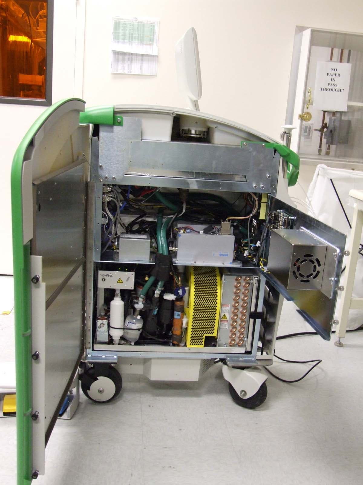
Click to zoom
Application Details
- Equipment Class
- DXT - Part 15 Low Power Transceiver, Rx Verified
- Date of Grant
- Nov 06, 2006
- Application Purpose
- Original Equipment
- Date of Application
- Nov 06, 2006
- Equipment Note
- RFID sub-system for the GreenLight HPS
- Frequency Range
- 13.56000000 - 13.56000000
- Company
- Laserscope, Inc.
- Country
- United States
Documents & Files
Document Text
Text extracted from the exhibit documents filed with the FCC. Open a document above to read the original.
Users Manual
Laser Operator’s Manual Manufactured by 3070 Orchard Drive San Jose, CA 95134 (800) 356-7600 +1 (408) 943-0636 Part No. 0010-0009 Rev. A Copyright © 2006 Laserscope. All right reserved. Notice No part of this manual may be reproduced or transmitted in any form or by any means without the written consent of Laserscope. The information in this manual is subject to change without notice. Disclaimer Laserscope provides this document in its commitment to help facilitate consistent, positive clinical outcomes, and to reduce patient risk and injury. These guidelines are not, however, intended to in any way replace or substitute a physician’s duty of care, professional responsibility, or professional judgment, nor are they intended to provide any warranty, promise, guarantee, assumption of risk or duty, release, or indemnity. Physicians shall at all times maintain responsibility for patient treatment and outcomes, and Laserscope further assumes no liability for patient treatment or outcome or for physician’s negligence, breach of duty of care, or malpractice. In no way does this or any of Laserscope’s policies, procedures, training materials, guidelines, or instructions create an obligation for Laserscope to perform any services. Products and services may be purchased from Laserscope. Trademarks GreenLight HPS is a Laserscope trademark Laserscope is a registered trademark of Laserscope. Laserscope Corporate Headquarters 3070 Orchard Drive San Jose, CA 95134-2011 U.S.A. Tel: 800 356-7600 (Customer Service) Tel: 408 943-0636 Fax: (+1) 408 943-1051 www.laserscope.com Laserscope France, S.A. Parc Technologique 18 rue du Bois Chaland 91090 Lisses, France Tel: 33/1 60 86 20 49 Fax: 33/1 60 86 14 88 Laserscope (UK) Ltd. Berwyn, The Pavilions Llantarnam Park Cwmbran, South Wales, NP44 3UW United Kingdom Tel: 44/1633-838081 Fax: 44/1633-838161 iii TABLE OF CONTENTS Preface .............................................................................................. v About This Manual......................................................................... v Conventions ................................................................................ vi Who Should Read This Manual ....................................................... vi Obtaining Help............................................................................. vi Safety .............................................................................................. vii Eye Injury...................................................................................vii Burns ........................................................................................ xiii Reflection of the Beam from Instruments ....................................... xiii Ignition of Flammable Materials .................................................... xiv Vapor/Smoke Plume .................................................................... xiv Electrical.................................................................................... xiv Operating Room Environment ........................................................xv Reference Sources ..................................................................... xvii Safety Features of the GreenLight HPS ™ ....................................... xviii Safety Classifications ................................................................... xix Labeling .................................................................................... xxi Section 1: Introduction ..................................................................... 1 1.1 System Overview .................................................................. 1 1.2 GreenLight HPS Fiber Optic..................................................... 6 1.3 General Instructions for Use ................................................... 7 1.4 Sterilization.......................................................................... 8 Section 2: System Installation ......................................................... 9 2.1 Responsibility ....................................................................... 9 2.2 Space and Power Requirements ............................................ 10 Section 3: Operating the System..................................................... 11 3.1 The Touch Screen and Footswitch .......................................... 11 3.2 Turning the System On........................................................ 12 3.3 Operating Procedure ........................................................... 16 3.4 Turning the System Off ........................................................ 20 Section 4: Physician Information .................................................... 21 4.1 Training Requirements ......................................................... 21 4.2 Indications ......................................................................... 21 4.3 Contraindications......................... ............................................. 21 4.4 Potential Complications and Risks .......................................... 22 4.5 Precautions ................................................. 22 Section 5: Maintenance ................................................................... 25 5.1 Care of the Console............................................................ 25 5.2 Coolant Refill Instructions ................................................... 25 5.3 Preventive Maintenance Schedule ........................................ 26 iv Section 6: Troubleshooting ............................................................. 27 6.1 System Prompts ................................................................. 27 6.2 Service Prompts.................................................................. 28 Specifications................................................................................... 29 Warranty.......................................................................................... 30 Warranty Policy ...............…
Text truncated - open the document above for the full version.
Attestation Statements
Chris Harvey From: Jennifer Sanchez [[email protected]] Sent: Thursday, November 02, 2006 5:10 PM To: Chris Harvey Cc: Marie Confroy; Tony Permsombut; Jennifer Sanchez Subject: RE: Additional Information needed MT#20187 - LaserScope Page 1 of 2 11/3/2006 Hi Chris, Please see responses below. Let me know if you need any further information. Jennifer Sanchez 510-489-6300 ext 612 http://www.metlabs.com -----Original Message----- From: Chris Harvey [mailto:[email protected]] Sent: Tuesday, October 31, 2006 3:38 AM To: Jennifer Sanchez Cc: Marie Confroy; Tony Permsombut Subject: Additional Information needed MT#20187 - LaserScope Marie, I have performed the initial review of the above referenced application and find that the following items need to be addressed before the review can be completed: 1. Please include photographs of the entire PC Board that contains the RF Circuitry as well as the antenna that is connected to this board in the Internal Photo exhibit. Additionally, please provide an antenna description/specification sheet. Please see files: Data sheet.pdf, laserscope-Antenna-RevB-Layout-06.pdf, Antenna Drawing.pdf & laserscope-Antenna-RevB- Fab&Assembly-Dwgs-05.pdf, Internal Photographs.pdf 2. The text for the radiated emissions measurement procedure indicates that the RBW and VBW are set to 10kHz for measurements below 30MHz using a loop antenna. However, the plots provided on pages 13 & 14 show a RBW of 1Khz and a VBW of 3kHz. Please explain and indicate how compliance with the limits was determined. Final measurements were taken with 10 KHz RBW; where as some of the plots given were taken with 1 KHz. (Due the difficulty caused by the nature of EUT.) Furthermore additional points were taken in the band of interest and compared with the plots and no differences were observed in this particular case. Please also indicate the detector type that was used to measure these emissions. Regarding detectors, for the plots Peak detector was used. 3. Please provide information about the RFID tags used with this device, including if they are classified as powered-tags, the return frequency, and the specifications. No power is provided to the RFID tag beyond the RF signal from the reader. The tag returns 13.56 MHz. Please provide a single response that addressed the above issues, but please feel free to contact me with questions. Best regards, Chris Harvey [email protected] -----Original Message----- From: Jennifer Sanchez [mailto:[email protected]] Sent: Friday, October 27, 2006 2:45 PM To: [email protected] Cc: [email protected]; [email protected]; [email protected] Subject: 20187 - LaserScope - METrak Mail From: Jennifer Sanchez Importance: High Job Number: 20187 Model Desc: RFID sub-system for the GreenLight HPS Customer Name: LaserScope Customer Code: LAS2 ----------------------------------------------------- Task Number: 290032 Task Description: EMC/TCB Application Task Status: In Progress Hi Chris, Please accomplish technical review for the FCC TCB this project with the following information: H:\METrak_Job_Folders\2006\L\LaserScope - LAS2\20187\TCB\Customer Info Please keep in mind that our turn around time for technical review is twenty-four to forty-eight hours. Let me know if I should provide you anything else, or if there may be any delays you may foresee in reviewing. Thanks! Jennifer Sanchez Page 2 of 2 11/3/2006
External Photos
Laserscope GreenLight HPS External Photographs Laserscope GreenLight HPS Laserscope GreenLight HPS Laserscope GreenLight HPS Laserscope GreenLight HPS Laserscope GreenLight HPS Laserscope GreenLight HPS
Internal Photos
Laserscope GreenLight HPS Internal Photographs Laserscope GreenLight HPS Antenna Component Side Antenna Solder Side Laserscope GreenLight HPS Board & Enclosure Component Side Board & Enclosure Solder Side Laserscope GreenLight HPS Enclosure Laserscope GreenLight HPS RFID Component Side RFID Solder Side Laserscope GreenLight HPS RFID Tag Bottom Laserscope GreenLight HPS RFID Tag Top
Operational Description
INTEGRATED CIRCUITS Standard Card IC MF1 IC S50 Functional Specification May 2001 Product Specification Revision 5.1 Philips Semiconductors Philips SemiconductorsProduct Specification Rev. 5.1 Mai 2001 Functional SpecificationStandard Card IC MF1 IC S50 2 CONTENTS 1FEATURES.......................................................................................................................4 1.1MIFARE RF Interface (ISO/IEC 14443 A)..........................................................................4 1.2EEPROM..........................................................................................................................4 1.3Security............................................................................................................................4 2GENERAL DESCRIPTION.................................................................................................5 2.1Contactless Energy and Data Transfer................................................................................5 2.2Anticollision.......................................................................................................................5 2.3User Convenience.............................................................................................................5 2.4Security............................................................................................................................5 2.5Multi-application Functionality.............................................................................................5 2.6Delivery Options................................................................................................................6 3FUNCTIONAL DESCRIPTION............................................................................................6 3.1Block Description...............................................................................................................6 3.2Communication Principle....................................................................................................7 3.2.1REQUEST STANDARD / ALL............................................................................................7 3.2.2ANTICOLLISION LOOP.....................................................................................................7 3.2.3SELECT CARD.................................................................................................................7 3.2.43 PASS AUTHENTICATION...............................................................................................7 3.2.5MEMORY OPERATIONS...................................................................................................8 3.3Data Integrity.....................................................................................................................8 3.4Security............................................................................................................................8 3.4.1THREE PASS AUTHENTICATION SEQUENCE..................................................................8 3.5RF Interface......................................................................................................................8 3.6Memory Organisation.........................................................................................................9 3.6.1MANUFACTURER BLOCK..............................................................................................10 3.6.2DATA BLOCKS...............................................................................................................10 3.6.3SECTOR TRAILER (BLOCK 3)........................................................................................11 3.7Memory Access..............................................................................................................12 3.7.1ACCESS CONDITIONS...................................................................................................13 3.7.2ACCESS CONDITIONS FOR THE SECTOR TRAILER......................................................13 3.7.3ACCESS CONDITIONS FOR DATA BLOCKS...................................................................15 4DEFINITIONS.................................................................................................................16 Philips SemiconductorsProduct Specification Rev. 5.1 Mai 2001 Functional SpecificationStandard Card IC MF1 IC S50 3 5LIFE SUPPORT APPLICATIONS.....................................................................................16 6REVISION HISTORY.......................................................................................................17 MIFARE is a registered trademark of Philips Electronics N.V. Philips SemiconductorsProduct Specification Rev. 5.1 Mai 2001 Functional SpecificationStandard Card IC MF1 IC S50 4 1 FEATURES 1.1 MIFARE RF Interface (ISO/IEC 14443 A) • Contactless transmission of data and supply energy (no battery needed) • Operating distance: Up to 100mm (depending on antenna geometry) • Operating frequency: 13.56 MHz • Fast data transfer: 106 kbit/s • High data integrity: 16 Bit CRC, parity, bit coding, bit counting • True anticollision • Typical ticketing transaction: < 100 ms (including backup management) 1.2 EEPROM • 1 Kbyte, organized in 16 sectors with 4 blocks of 16 bytes each (one block consists of 16 byte) • User definable access conditions for each memory block • Data retention of 10 years. • Write endurance 100.000 cycles 1.3 Security • Mutual three pass authentication (ISO/IEC DIS9798-2) • Data encryption on RF-channel with replay attack protection • Individual set of two keys per sector (per application) to support multi-application with key hierarchy • Unique serial number for each device • Transport key protects access to EEPROM on chip delivery Philips SemiconductorsProduct Specification Rev. 5.1 Mai 2001 Functional SpecificationStandard Card IC MF1 IC S50 5 2 GENERAL DESCRIPTION Philips has developed the MIFARE ® MF1 IC S50 to b…
Text truncated - open the document above for the full version.
Operational Description
INTEGRATED CIRCUITS MF RC531 ISO 14443 Reader IC April 2005 Short Form Specification Revision 3.2 Philips Semiconductors Philips SemiconductorsShort Form Specification Rev. 3.2 April 2005 ISO 14443A Reader ICMF RC531 2PUBLIC CONTENTS 1INTRODUCTION.......................................................3 1.1Scope.......................................................................3 1.2Features...................................................................3 1.3Applications..............................................................3 2BLOCK DIAGRAM....................................................4 3MF RC531 PINNING.................................................5 3.1Pinning Diagram........................................................5 3.2Pin Description..........................................................6 3.2.1Antenna Interface.....................................................6 3.2.2Analog Supply..........................................................6 3.2.3Digital Supply............................................................6 3.2.4Auxillary Pin..............................................................6 3.2.5Reset Pin...................................................................7 3.2.6Oscillator...................................................................7 3.2.7MIFARE Interface...................................................7 3.2.8Parallel Interface.......................................................7 3.2.9SPI Compatible Interface..........................................8 3.3Applications..............................................................8 3.3.1Connecting Different μController's............................8 3.3.2Application Example..................................................9 4MIFARE ® CLASSIC RELATED ITEMS...................10 4.1CRYPTO I: Card Authentication.............................10 4.1.1Initiating Card Authentication..................................10 4.1.2Second Part of Card Authentication........................10 5ELECTRICAL SPECIFICATION..............................11 5.1DC Characteristics..................................................11 5.2Start up Characteristics..........................................11 6REVISION HISTORY..............................................12 MIFARE is a registered trademark of Philips Electronics N.V Philips SemiconductorsShort Form Specification Rev. 3.2 April 2005 ISO 14443A Reader ICMF RC531 3PUBLIC 1 INTRODUCTION 1.1 Scope The MF RC531 is member of a new family of highly integrated reader ICs for contactless communication at 13.56 MHz. This reader IC family utilises an outstanding modulation and demodulation concept completely integrated for all kinds of passive contactless communication methods and protocols at 13.56 MHz. The MF RC531 is pin- compatible to the MF RC500, the MF RC530 and the SL RC400. The Philips IC MF RC531 supports all layers of the ISO/IEC 14443A/B communication scheme, given correct implementation of additional components, like oscillator, power supply, coil etc. and provided that standardised protocols, e.g. like ISO/IEC 14443-4 and/or ISO/IEC 14443 type B anticollision are correctly implemented. The use of this Philips IC according to ISO14443 Type B might infringe third party patent rights. The MF RC531 supports contactless communication using MIFARE ® Higher Baudrates. The internal transmitter part is able to drive an antenna designed for proximity operating distance (up to 100 mm) directly without additional active circuitry. The receiver part provides a robust and efficient implementation of a demodulation and decoding circuitry for signals from ISO14443 compatible transponders. The digital part handles the complete ISO14443 framing and error detection (Parity & CRC). Additionally it supports the fast MIFARE ® Classic security algorithm to authenticate MIFARE Classic (e.g. MIFARE ® Standard) products. A comfortable parallel interface, which can be directly connected to any 8-bit μ-Processor gives high flexibility for the reader/terminal design. Additionally a SPI compatible interface is supported. A purchaser of this Philips IC has to take care for appropriate third party patent licenses. 1.2 Features • Highly integrated analog circuitry to demodulate and decode card response • Buffered output drivers to connect an antenna with minimum number of external components • Proximity operating distance (up to 100 mm) • Supports ISO 14443 • Supports MIFARE ® Dual Interface Card ICs and supports MIFARE ® Classic protocol • Supports contactless communication with higher baudrates up to 424kHz • Crypto1 and secure non-volatile internal key memory • Pin-compatible to the MF RC500, MF RC530 and the SL RC400 • Parallel μ-Processor interface with internal address latch and IRQ line • SPI compatible interface • Flexible interrupt handling • Automatic detection of the used μ-Processor interface type • Comfortable 64 byte send and receive FIFO- buffer • Hard reset with low power function • Power down mode per software • Programmable timer • Unique serial number • Bit- and byte-oriented framing • Internal oscillator buffer to connect 13.56 MHz quartz, optimised for low phase jitter • 3.3 V to 5 V operation for transmitter (antenna driver) in short range and proximity applications • 3.3 V or 5V operation for the digital part 1.3 Applications The MF RC531 is tailored to fit the requirements of various applications using contactless communication based on ISO/IEC 14443 standard where cost-effectiveness, small size, high performance with a single voltage supply are important. • Public transport terminals • Handheld terminals • On board units • Contactless PC terminals • Metering • Contactless public phones Philips SemiconductorsShort Form Specification Rev. 3.2 April 2005 ISO 14443A Reader ICMF RC531 4PUBLIC 2 BLOCK DIAGRAM The block diagram shows the main internal parts of the MF RC531. The parallel μController interface automatically detects the kind of 8 bit…
Text truncated - open the document above for the full version.
Operational Description
INTEGRATED CIRCUITS MF RC531 ISO 14443 Reader IC April 2005 Short Form Specification Revision 3.2 Philips Semiconductors Philips SemiconductorsShort Form Specification Rev. 3.2 April 2005 ISO 14443A Reader ICMF RC531 2PUBLIC CONTENTS 1INTRODUCTION.......................................................3 1.1Scope.......................................................................3 1.2Features...................................................................3 1.3Applications..............................................................3 2BLOCK DIAGRAM....................................................4 3MF RC531 PINNING.................................................5 3.1Pinning Diagram........................................................5 3.2Pin Description..........................................................6 3.2.1Antenna Interface.....................................................6 3.2.2Analog Supply..........................................................6 3.2.3Digital Supply............................................................6 3.2.4Auxillary Pin..............................................................6 3.2.5Reset Pin...................................................................7 3.2.6Oscillator...................................................................7 3.2.7MIFARE Interface...................................................7 3.2.8Parallel Interface.......................................................7 3.2.9SPI Compatible Interface..........................................8 3.3Applications..............................................................8 3.3.1Connecting Different μController's............................8 3.3.2Application Example..................................................9 4MIFARE ® CLASSIC RELATED ITEMS...................10 4.1CRYPTO I: Card Authentication.............................10 4.1.1Initiating Card Authentication..................................10 4.1.2Second Part of Card Authentication........................10 5ELECTRICAL SPECIFICATION..............................11 5.1DC Characteristics..................................................11 5.2Start up Characteristics..........................................11 6REVISION HISTORY..............................................12 MIFARE is a registered trademark of Philips Electronics N.V Philips SemiconductorsShort Form Specification Rev. 3.2 April 2005 ISO 14443A Reader ICMF RC531 3PUBLIC 1 INTRODUCTION 1.1 Scope The MF RC531 is member of a new family of highly integrated reader ICs for contactless communication at 13.56 MHz. This reader IC family utilises an outstanding modulation and demodulation concept completely integrated for all kinds of passive contactless communication methods and protocols at 13.56 MHz. The MF RC531 is pin- compatible to the MF RC500, the MF RC530 and the SL RC400. The Philips IC MF RC531 supports all layers of the ISO/IEC 14443A/B communication scheme, given correct implementation of additional components, like oscillator, power supply, coil etc. and provided that standardised protocols, e.g. like ISO/IEC 14443-4 and/or ISO/IEC 14443 type B anticollision are correctly implemented. The use of this Philips IC according to ISO14443 Type B might infringe third party patent rights. The MF RC531 supports contactless communication using MIFARE ® Higher Baudrates. The internal transmitter part is able to drive an antenna designed for proximity operating distance (up to 100 mm) directly without additional active circuitry. The receiver part provides a robust and efficient implementation of a demodulation and decoding circuitry for signals from ISO14443 compatible transponders. The digital part handles the complete ISO14443 framing and error detection (Parity & CRC). Additionally it supports the fast MIFARE ® Classic security algorithm to authenticate MIFARE Classic (e.g. MIFARE ® Standard) products. A comfortable parallel interface, which can be directly connected to any 8-bit μ-Processor gives high flexibility for the reader/terminal design. Additionally a SPI compatible interface is supported. A purchaser of this Philips IC has to take care for appropriate third party patent licenses. 1.2 Features • Highly integrated analog circuitry to demodulate and decode card response • Buffered output drivers to connect an antenna with minimum number of external components • Proximity operating distance (up to 100 mm) • Supports ISO 14443 • Supports MIFARE ® Dual Interface Card ICs and supports MIFARE ® Classic protocol • Supports contactless communication with higher baudrates up to 424kHz • Crypto1 and secure non-volatile internal key memory • Pin-compatible to the MF RC500, MF RC530 and the SL RC400 • Parallel μ-Processor interface with internal address latch and IRQ line • SPI compatible interface • Flexible interrupt handling • Automatic detection of the used μ-Processor interface type • Comfortable 64 byte send and receive FIFO- buffer • Hard reset with low power function • Power down mode per software • Programmable timer • Unique serial number • Bit- and byte-oriented framing • Internal oscillator buffer to connect 13.56 MHz quartz, optimised for low phase jitter • 3.3 V to 5 V operation for transmitter (antenna driver) in short range and proximity applications • 3.3 V or 5V operation for the digital part 1.3 Applications The MF RC531 is tailored to fit the requirements of various applications using contactless communication based on ISO/IEC 14443 standard where cost-effectiveness, small size, high performance with a single voltage supply are important. • Public transport terminals • Handheld terminals • On board units • Contactless PC terminals • Metering • Contactless public phones Philips SemiconductorsShort Form Specification Rev. 3.2 April 2005 ISO 14443A Reader ICMF RC531 4PUBLIC 2 BLOCK DIAGRAM The block diagram shows the main internal parts of the MF RC531. The parallel μController interface automatically detects the kind of 8 bit…
Text truncated - open the document above for the full version.
Schematics
55 44 33 22 11 D D C C B B A A B 0133- 0490 B Laser Control Board, GLHPS - Fiber Interface Custom 13 13 Wednesday, May 31, 2006 TitleSize Document Number Rev Date: Sheet of 3070 ORCHARD DRIVE SAN JOSE, CA 95134-2011 uCDATA7uCDATA6uCDATA5uCDATA4uCDATA3uCDATA2uCDATA1uCDATA0 uCADDR2uCADDR1uCADDR0 RFIRQ 5 RFRST 5 RFCSn 5 uCALE 5 uCRDn 4,5 uCWRn 4,5 uCADDR[5:0] 4,5,12 uCDATA[7:0] 4,5 RF +3.3D D +5.0D RF RF +5.0D D RF RF C13130.1uF25V R13004.99K1/10W C13140.1uF25V W1301 R13104991/10W + C130247uF6.3V TP1300 C1322220pF50V TP1301 + C130147uF6.3V C133022pF50V TP1302 C13120.1uF25V C13110.1uF25V C133122pF50V C1321120pF50V R13208251/10W J13005227161-3RF I/O 1 2 Y130013.5600MHz C1320120pF50V C1326FS50V W1300 C13100.1uF25V + C130047uF6.3V L13111.2uH L1300BEAD C1340FS50V L13101.2uH U1300MF RC531RFID Reader 12 345 6 78 9 1011 12 131415161718192021222324 25 26 27 28 2930 3132 OSCINIRQ MFIN MFOUT TX1 TXVDD TX2 TXVSS CS#WR#RD# DVSS D0D1D2D3D4D5D6D7ALEA0A1A2 DVDD AVDD AUX AVSS RX VMID RSTOSCOUT
Test Report
MET Laboratories, Inc. Safety Certification - EMI - Telecom Environmental Simulation 33439 WESTERN AVENUE ! UNION CITY, CALIFORNIA 94587-3201 ! PHONE (510) 489-6300 ! FAX (510) 489-6372 The Nation’s First Licensed Nationally Recognized Testing Laboratory August 2, 2006 LaserScope 3070 Orchard Drive San Jose, CA 95134-2011 Dear Bill Wong, Enclosed is the EMC test report for compliance testing of the LaserScope, RFID Subsystem, tested to the requirements of Title 47 of the CFR, Part 15, Subpart B and Part 15.225, Subpart C for Certification as an Intentional Radiator. Thank you for using the services of MET Laboratories, Inc. If you have any questions regarding these results or if MET can be of further service to you, please feel free to contact me. Sincerely yours, MET LABORATORIES, INC. Cheryl Anicete Documentation Department Reference: (\LaserScope\ EMCU20187-FCC225) Certificates and reports shall not be reproduced except in full, without the written permission of MET Laboratories, Inc. While use of the Nat…
Text truncated - open the document above for the full version.
Contact Information
Applicant
Van Frazier(VP Regulatory Affairs)
Test Firm
MET LaboratoriesAlvin Ilarina
Technical Specifications
| # | Rule Parts | Frequency Range | Power Output |
|---|---|---|---|
| 1 | 15C | 13.56 MHz - 13.56 MHz | - |