UEGNEOSMC56Fixed Wireless Terminal
Gainwise Technology Co., Ltd.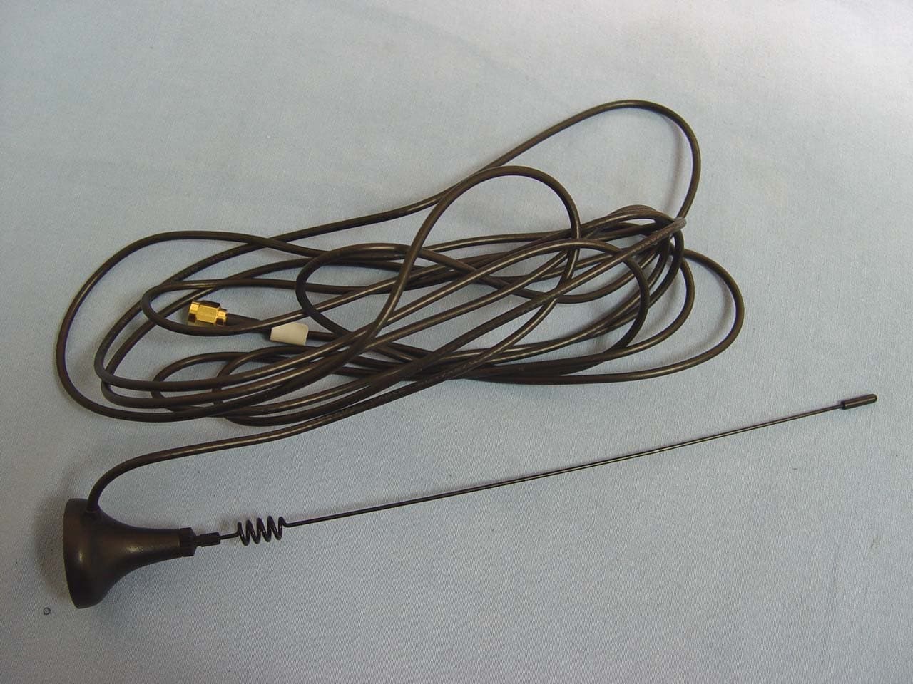
Click to zoom
Application Details
- Equipment Class
- PCB - PCS Licensed Transmitter
- Date of Grant
- Aug 07, 2006
- Application Purpose
- Original Equipment
- Date of Application
- Aug 07, 2006
- Equipment Note
- Fixed Wireless Terminal
- Frequency Range
- 1850.20000000 - 1909.80000000
- Country
- Taiwan
Documents & Files
Document Text
Text extracted from the exhibit documents filed with the FCC. Open a document above to read the original.
Users Manual
GAINWISE NEOS PBX MOBILE TRUNK MANUAL NEOS3000 NEOS3000 Series 1 USER MANUAL NEOS3000 SERIES 2 USER MANUAL A. INTRODUCTION Thank you for choosing the NEOS3000AB2 series product from Gainwise. This innovative product make you connect to standard telephone equipment with GSM engine into a cellular network for total communications flexibility. You can connect the NEOS3000AB2 to the land phone or the analog trunk of the PABX or key system. B. CHECKING YOUR PARTS Item Description Qty Included Optional 1 NEOS3000AB2 1 2 DC12V/1A Switching Adapter 1 3 Phone Cord 1 4 Telephone Box 1 5 Male SMA Antenna 1 6 Operation Manual 1 7 Display 1 8 Data Cable 1 9 SCM50 1 C. SYSTEM ARCHITECTURE D. INSTALLATION (see diagram below) 1. SIM Card Installation(figure 1) 1-1. Remove the 12VDC switching adapter 1-2. Gently insert the mini-SIM card in the slot of bottom of NEOS3000AB2 1-3. Make sure the SIM card is put exactly 1-4. Attach the 12VDC switching adapter NEOS3000 SERIES 3 USER MANUAL 2. Connect the antenna to the SMA antenna connector on the back of NEOS3000AB2. 3. Connect The Power and Plug In Your Telephone Equipment(figure 2 and 3) 3-1. Connect the LINE port of NEOS3000AB2 with wall jack of PSTN. (If you don’t have PSTN or need LCR, you don’t do it.) 3-2. Connect one end of phone cord to the PHONE port of NEOS3000AB2 and the other end to the analog port of the PABX. (or key system or the land phone) 3-3. Connect the switching adapter to the DC jack of NEOS and AC power. 3-4. All steps are finished, the red led and green led turn on. NEOS3000 SERIES 4 USER MANUAL 4. LED Status Indicators Position LED Color LED Activity Description 1 RED Continuous ON or OFF The DC power is ON or OFF 2 YELLOW Continuous ON The PSTN line is idle. 2 YELLOW Flashing(0.05sec ON / 0.05sec OFF) The PSTN line is talking. 3 GREEN Continuous ON The GSM phone is idle. 3 GREEN Flashing(0.05sec ON / 0.05sec OFF) The GSM line is talking. 3 GREEN Flashing(0.25sec ON / 0.25sec OFF) The redial tone of NEOS. 3 GREEN Flashing(0.5sec ON / 0.5sec OFF) The busy tone of NEOS. 4 GREEN Continuous OFF The engine is OFF, in SLEEP, ALARM 4 GREEN Flashing(0.6sec ON / 0.6sec OFF) No SIM card, no PIN entered, network searching 4 GREEN Flashing(0.075sec ON / 3sec OFF) Logged on a network but no call in progress 4 GREEN Continuous ON Connected to remote party 2&3 GREEN and YELLOW Flashing three time in one second Enter the Setup Mode 2&3 GREEN and YELLOW Flashing(0.25sec ON / 1.75sec OFF) Enter the Programming Mode E. HOW TO USE 1. Pick up your telephone handset. 2. Listen for dial tone. (If there is no tone, you have to check the GSM engine signal) 3. Dial the phone number. F. PROGRAMMING MODE 1. Pick up the telephone handset and listen for the dial tone. Press thethen enter the setup mode. You can hear the Du Du Du tone (three times per second). 2. Press the password to enter programming mode, the default value is1234 2-1. When the password is correct, the green LED and yellow LED of NEOS will flash and you hear short Du tone (one time per second). We call it setup tone. 2-2. When the password is wrong, the green LED and yellow LED of NEOS will flash and you hear three Du tones then back to the setup mode. 3. In programming mode you can press the function code to program the feature you want. (check the table of function code) 3-1. If the programming is successful, the green LED and yellow LED of NEOS will flash one time and you can hear one Du tone. You can program the other function. 3-2. If the programming is fail, the green LED and yellow LED of NEOS will flash three times and you can hear three Du tones. If you hear setup tone, you can reprogram the function 3-3. You can hang up the handset to cancel this programming when you press wrong code. 3-4. Pressor hang up the handset over two second if you want to quit the programming mode. NEOS3000 SERIES 5 USER MANUAL G. FUNCTION DESCRIPTION (Reference FUNCTION CODE TABLE) 1. Outgoing Time Control 1-1. NEOS will emit three Du Du Du tones at 25 seconds before the end of the outgoing time that you program. It reminds you that this call will be finished. 1-2. Press90Xto set the outgoing time from 1 to 9 minutes. Χ is 1 to 9. 1-3. Press911to disable NEOS to finish the call when outgoing time is up. But NEOS will emit the reminding tone per minute. 1-4. Press912to enable NEOS to finish the call when outgoing time is up. 1-5. Press900to set that NEOS don’t restrict the outgoing time. 2. Call Restriction ( It is useful when you remove phone cord from line port of NEOS) 2-1. Press916to enable the call restriction. You can call when the prefix of phone number match permissible dialing number or else you can not call and hear Du Du Du tone. 2-2. Press915to disable the call restriction. You can call all number when you don’t connect wall jack to line of NEOS. NoteIf you press916to enable the call restriction and the permissible dialing number is empty, you can not call at all. 3. Permissible Dialing Number 3-1. Press80XXXXXXXXto add the prefix number. Χ represents digit of number. One prefix is up to 9 numbers and total is up to 50 sets. 3-2. Press70XXXXXXXXto delete the prefix number. 3-3. Press998to clear all permissible dialing number. 3-4. If you connect wall jack to NEOS, the permissible dialing number will become router between PSTN and GSM network. 4. Outgoing Tone 4-1. Press927to disable the beeping tone when you call via GSM network. 4-2. Press928to enable the beeping tone when you call via GSM network. 5. Polarity Reversal 5-1. Polarity reversal of outgoing call description When the outgoing call is connecting NEOS will reverse the polarity. If anyone hangs up the phone, then NEOS reverse the polarity back. 5-2. Polarity reversal of incoming call description When you pick up your handset NEOS reverse the polarity. If anyone hangs up the phone, then NEOS reverse the polarity back. 5-3. Polarity reversal Option Press963to disable polarity reversal of outgoing. Press964to enable polarity reversal of outg…
Text truncated - open the document above for the full version.
Cover Letter(s)
Compliance Certification Services Certification Division 561F Monterey Road Morgan Hill, CA 95037 To whom it may concern: We, the undersigned, hereby authorize the Taiwan office of Compliance Engineering Services, Inc., d.b.a. Compliance Certification Services and hereafter referred to as CCS TW, to act on our behalf in all manners relating to application for equipment authorization, including signing of all documents relating to these matters. Any and all acts carried out by CCS TW on our behalf shall have the same effect as acts of our own. We, the undersigned, hereby certify that we are not subject to a denial of federal benefits, that includes FCC benefits, pursuant to Section 5301 of the Anti-Drug Abuse Act of 1988, 21 U.S.C. 853(a). In authorizing CCS TW as our agent, we still recognize that we are responsible to: a) Comply with the relevant provisions of the certification program; b) Make all necessary arrangements for the conduct of the evaluation, including provision for examining documentation and access to all areas, records (including internal audit reports) and personnel for the purposes of evaluation (e.g. testing, inspection, assessment, surveillance, reassessment) and resolution of complaints; c) Make claims regarding certification only in respect of the scope for which certification has been granted; d) Do not use our product certification in such a manner as to bring the Certification Division into disrepute and not make any statement regarding our product certification which the Certification Division may consider misleading or unauthorized; e) Upon suspension or cancellation of certification, discontinue use of all advertising matter that contains any reference thereto and return any certification documents as required by the Certification Division; f) Use certification only to indicate the products are certified as being in conformity with specified standards; g) Endeavor to ensure that no certificate or report nor any part thereof is used in a misleading manner; h) Ensure that any reference to our product certification in communication media such as documents, brochures or advertising, complies with the requirements of the Certification Division; i) Keep a record of all complaints made known to the us relating to the product’s compliance with requirements of the relevant standard and to make these records available to the Certification Division when requested; j) Take appropriate action with respect to such complaints and any deficiencies found in products or services that affect compliance with the requirements for certification; k) Document the actions taken. This authorization is valid until further written notice from the applicant. Sincerely Yours, REMARK: 1. This authorization letter will be sent along with your application when filing with the Certification Division. 2. Please follow the format and type it on company letterhead and send original to us.
Cover Letter(s)
Chris Harvey From: jessica.ho [[email protected]] on behalf of application [[email protected]] Sent: Thursday, July 27, 2006 12:11 AM To: [email protected] Subject: Re:Gainwise Technology Co. Ltd., FCC ID: UEGNEOSMC56, Assessment NO.: AN06T5964, Notice#1 Attachments: NEOS3000A MPE revised 0726.pdf; NEOS3000A Ant spec. revised 0726.pdf; NEOS3000A TestRpt revised 0726.pdf Page 1 of 2 7/27/2006 Dear Sir: Please see my reply, thank you. Best Regards, Amanda Dear Amanda Wu, I have reviewed the above referenced TCB application and find that the following items need to be addressed before the review can be completed: 1. The Schematics submitted with this application doe not seem to contain the RF circuitry. Please submit a revised schematic diagram that includes the RF Circuitry. Ans:The sales will reply to Mike directly. 2. Please submit an exhibit for RF Exposure compliance of this device which justifies the 20cm separation statement in the Users Manual. Ans: 3. Please confirm that this device does not have GPRS capabilities. Ans:There are functions in the Module,but there are not functions in the product. <[email protected]> 2006/07/26 03:50 AM 收件人: <[email protected]> 副本抄送: <[email protected]>, <[email protected]> 主旨: Gainwise Technology Co. Ltd., FCC ID: UEGNEOSMC56, Assessment NO.: AN06T5964, Notice#1 4. Please confirm the antenna gain and cable loss information provided for both the 850MHz and the 1.9GHz bands. Ans: 5. Please provide the DC Voltages for the final RF amplification stages and the Tune-Up information (typically found in Operational Description) as required by FCC 2.1033. Ans:The sales will reply to Mike directly. The items indicated above must be submitted before processing can continue on the above referenced application. Failure to provide the requested information within 30 days of the original e-mail date may result in application dismissal and forfeiture of the filing fee. Also, please note that partial responses increase processing time and should not be submitted. Any questions about the content of this correspondence should be directed to the e-mail address listed below the name of the sender. Best regards, Chris Harvey [email protected] Page 2 of 2 7/27/2006
Cover Letter(s)
Chris Harvey From: amanda.wu [[email protected]] on behalf of application [[email protected]] Sent: Wednesday, August 02, 2006 5:20 AM To: [email protected]; [email protected] Subject: Re:Gainwise Technology Co. Ltd., FCC ID: UEGNEOSMC56, Assessment NO.: AN06T5964, Notice#2 Attachments: NEOS3000A MPE Revised 0802.pdf; NEOS3000A TestRpt revised 0726.pdf Page 1 of 2 8/3/2006 Dear Chris: Sorry for troubling you, I'll point out why, where and what had been changed to the test report onwards. Dear Mike: Salesman just informed that client (Mr. Peter) had send OpDes, tune up producess and schematics directly to you, can sir please help me to redirect the documents to Chris? Thanks! Best Regards, Amanda Dear Amanda Wu, I have received your first response to the first notice for the above referenced application. 1. There are several items requested that have yet to be submitted. Please note that I must review these additional exhibits before the technical review of the application can be completed. Ans: Salesman just informed that client (Mr. Peter) had send OpDes, tune up producess and schematics directly to Mike on 1st of August. <[email protected]> 2006/08/02 02:41 AM 收件人: <[email protected]> 副本抄送: <[email protected]> 主旨: Gainwise Technology Co. Ltd., FCC ID: UEGNEOSMC56, Assessment NO.: AN06T5964, Notice#2 2. The submitted MPE exhibit has some errors. This device is a dual band 850/1900 mobile device. The MPE exhibit mentions DTS and WLAN in a couple places and shows the limit as 1mW/cm2 (850 MHz band should have a limit of f/1500= 850/1500 = 0.567wm/cm2). Since the antenna-gain and the limits are different for the 2 frequency bands, please provide MPE calculation for both bands and correct/remove the references to DTS and WLAN. Ans: We revised the MPE exhibit, please have the attachments. 3. There was a revised test report exhibit submitted in the response but no indication why the report was revised or what has changed. Please provide an explanation as to what has changed from the original test report. Ans: We revised the antenna gain on page 4, please have the revised test report. The items indicated above must be submitted before processing can continue on the above referenced application. Failure to provide the requested information within 30 days of the original e-mail date may result in application dismissal and forfeiture of the filing fee. Also, please note that partial responses increase processing time and should not be submitted. Any questions about the content of this correspondence should be directed to the e-mail address listed below the name of the sender. Best regards, Chris Harvey [email protected] Page 2 of 2 8/3/2006
External Photos
Compliance Certification Services Inc. Report No: 60614101 Date of Issue: June 28, 2006 Page 1 Total Page: 8 Rev. 00 EXTERNAL PHOTOGRAPHS OF EUT Compliance Certification Services Inc. Report No: 60614101 Date of Issue: June 28, 2006 Page 2 Rev.00 Compliance Certification Services Inc. Report No: 60614101 Date of Issue: June 28, 2006 Page 3 Rev.00
Internal Photos
Compliance Certification Services Inc. Report No: 60614101 Date of Issue: June 28, 2006 Page 4 Rev.00 INTERNAL PHOTOGRAPHS OF EUT Compliance Certification Services Inc. Report No: 60614101 Date of Issue: June 28, 2006 Page 5 Rev.00 Compliance Certification Services Inc. Report No: 60614101 Date of Issue: June 28, 2006 Page 6 Rev.00 Compliance Certification Services Inc. Report No: 60614101 Date of Issue: June 28, 2006 Page 7 Rev.00 Compliance Certification Services Inc. Report No: 60614101 Date of Issue: June 28, 2006 Page 8 Rev.00
RF Exposure Info
Compliance Certification Services Inc. Report No.: 60614101-RP1 FCC ID: UEGNEOSMC56 Date of Issue: July 26, 2006 Page 1 Total Page: 2 Rev. 00 RADIO FREQUENCY EXPOSURE LIMIT See § 1.1307(b)(1) of this chapter. EUT Specification EUT Fixed Wireless Terminal Frequency band (Operating) 850 MHz 1900 MHz Device category Portable (<20cm separation) Mobile (>20cm separation) Others Exposure classification General Population/Uncontrolled exposure (S=0.567mW/cm 2 ) Antenna diversity Single antenna Multiple antennas Tx diversity Rx diversity Tx/Rx diversity Max. output power 850 MHz: 28.90 dBm (776.2 mW) Antenna gain (Max) -4.21 dBi (Numeric gain: 0.38) Evaluation applied MPE Evaluation* SAR Evaluation Remark: 1. The maximum output power is 28.90dBm (776.2mW) at 850MHz (with 0.38 numeric antenna gain.) 2. MPE estimate is used to justify the compliance. 3. For mobile or fixed location transmitters, no SAR consideration applied. The maximum power density is 0.567 mW/cm 2 even if the calculation indicates that the power density would be larger. TEST RESULTS No non-compliance noted. Compliance Certification Services Inc. Report No.: 60614101-RP1 FCC ID: UEGNEOSMC56 Date of Issue: July 26, 2006 Page 2 Rev. 00 Calculation Given d GP E ×× = 30 & 3770 2 E S= Where E = Field strength in Volts / meter P = Power in Watts G = Numeric antenna gain d = Distance in meters S = Power density in milliwatts / square centimeter Combining equations and re-arranging the terms to express the distance as a function of the remaining variables yields: 2 3770 30 d GP S ×× = Changing to units of mW and cm, using: P (mW) = P (W) / 1000 and d (cm) = d(m) / 100 Yields () () 22 0796.0 100/3770 1000/30 d GP d GP S × ×= × ×× = Equation 1 Where d = Distance in cm P = Power in mW G = Numeric antenna gain S = Power density in mW / cm 2 Maximum Permissible Exposure EUT output power = 776.2mW Numeric Antenna gain = 0.38 Substituting the MPE safe distance using d = 20 cm into Equation 1: Yields GPS××=000199.0 Where P = Power in mW G = Numeric antenna gain S = Power density in mW / cm 2 Æ Power density = 0.0587 mW / cm 2 (For mobile or fixed location transmitters, the maximum power density is 0.567 mW/cm 2 even if the calculation indicates that the power density would be larger. Compliance Certification Services Inc. Report No.: 60614101-RP1 FCC ID: UEGNEOSMC56 Date of Issue: July 26, 2006 Page 1 Total Page: 2 Rev. 00 RADIO FREQUENCY EXPOSURE LIMIT See § 1.1307(b)(1) of this chapter. EUT Specification EUT Fixed Wireless Terminal Frequency band (Operating) 850 MHz 1900 MHz Device category Portable (<20cm separation) Mobile (>20cm separation) Others Exposure classification General Population/Uncontrolled exposure (S=1.267mW/cm 2 ) Antenna diversity Single antenna Multiple antennas Tx diversity Rx diversity Tx/Rx diversity Max. output power 1900 MHz: 23.60 dBm (229.1 mW) Antenna gain (Max) -4.67 dBi (Numeric gain: 0.34) Evaluation applied MPE Evaluation* SAR Evaluation Remark: 1. The maximum output power is 23.60dBm (229.1mW) at 1900MHz (with 0.34 numeric antenna gain.) 2. DTS device is not subject to routine RF evaluation; MPE estimate is used to justify the compliance. 3. For mobile or fixed location transmitters, no SAR consideration applied. The maximum power density is1.267 mW/cm 2 even if the calculation indicates that the power density would be larger. TEST RESULTS No non-compliance noted. Compliance Certification Services Inc. Report No.: 60614101-RP1 FCC ID: UEGNEOSMC56 Date of Issue: July 26, 2006 Page 2 Rev. 00 Calculation Given d GP E ×× = 30 & 3770 2 E S= Where E = Field strength in Volts / meter P = Power in Watts G = Numeric antenna gain d = Distance in meters S = Power density in milliwatts / square centimeter Combining equations and re-arranging the terms to express the distance as a function of the remaining variables yields: 2 3770 30 d GP S ×× = Changing to units of mW and cm, using: P (mW) = P (W) / 1000 and d (cm) = d(m) / 100 Yields () () 22 0796.0 100/3770 1000/30 d GP d GP S × ×= × ×× = Equation 1 Where d = Distance in cm P = Power in mW G = Numeric antenna gain S = Power density in mW / cm 2 Maximum Permissible Exposure EUT output power = 229.1mW Numeric Antenna gain = 0.34 Substituting the MPE safe distance using d = 20 cm into Equation 1: Yields GPS××=000199.0 Where P = Power in mW G = Numeric antenna gain S = Power density in mW / cm 2 Æ Power density = 0.0155 mW / cm 2 (For mobile or fixed location transmitters, the maximum power density is 1.267 mW/cm 2 even if the calculation indicates that the power density would be larger.
Test Report
Compliance Certification Services Inc. Report No.: 60614101-RP1 FCC ID: UEGNEOSMC56 Date of Issue: June 28, 2006 Note: This report shall not be reproduced except in full, without the written approval of Compliance Certification Services Inc. This document may be altered or revised by Compliance Certification Services Inc. personnel only, and shall be noted in the revision section of the document. Page 1 Total Page: 55 Rev. 00 FCC 47 CFR PART 22 SUBPART H AND PART 24 SUBPART E TEST REPORT For Fixed Wireless Terminal Model: NEOS3000A Trade Name: Gainwise Issued to Gainwise Technology Co. Ltd. 10F-4, NO.12, Chung Hua Rd., Yung Kang City, Tainan Hsien, Taiwan, R.O.C Issued by Compliance Certification Services Inc. No. 81-1, Lane 210, Bade Rd. 2, Luchu Hsiang, Taoyuan Hsien, (338) Taiwan, R.O.C. http://www.ccsemc.com.tw [email protected] Compliance Certification Services Inc. Report No.: 60614101-RP1 FCC ID: UEGNEOSMC56 Date of Issue: June 28, 2006 Page 2 Rev. 00 TABLE OF CONTENTS 1. TEST RESULT CERTIFICATION............................................................................................. 3 2. EUT DESCRIPTION .................................................................................................................... 4 3. TEST METHODOLOGY ............................................................................................................. 5 3.1 EUT CONFIGURATION.............................................................................................................. 5 3.2 EUT EXERCISE......................................................................................................................... 5 3.3 GENERAL TEST PROCEDURES.................................................................................................. 5 3.4 DESCRIPTION OF TEST MODES................................................................................................. 5 4. INSTRUMENT CALIBRATION................................................................................................. 6 4.1 MEASURING INSTRUMENT CALIBRATION........................................................................... 6 4.2 MEASUREMENT EQUIPMENT USED .............................................................................. 6 5. FACILITIES AND ACCREDITATIONS ................................................................................... 8 5.1 FACILITIES.............................................................................................................................. 8 5.2 EQUIPMENT............................................................................................................................. 8 5.3 TABLE OF ACCREDITATIONS AND LISTINGS............................................................................ 9 6. SETUP OF EQUIPMENT UNDER TEST ................................................................................ 10 6.1 SETUP CONFIGURATION OF EUT............................................................................................ 10 6.2 SUPPORT EQUIPMENT .................................................................................................... 10 7. FCC PART 22 & 24 REQUIREMENTS ................................................................................... 11 7.1 AVERAGE POWER.............................................................................................................. 11 7.2 ERP & EIRP MEASUREMENT ......................................................................................... 13 7.3 OCCUPIED BANDWIDTH MEASUREMENT ................................................................. 16 7.4 OUT OF BAND EMISSION AT ANTENNA TERMINALS ............................................. 22 7.5 FIELD STRENGTH OF SPURIOUS RADIATION MEASUREMENT ............................ 32 7.6 FREQUENCY STABILITY V.S. TEMPERATURE MEASUREMENT ........................... 46 7.7 FREQUENCY STABILITY V.S. VOLTAGE MEASUREMENT ..................................... 48 7.8 POWERLINE CONDUCTED EMISSIONS.................................................................................... 50 Compliance Certification Services Inc. Report No.: 60614101-RP1 FCC ID: UEGNEOSMC56 Date of Issue: June 28, 2006 Page 4 Rev. 00 2. EUT DESCRIPTION Product Fixed Wireless Terminal Trade Name Gainwise Model Number NEOS3000A Model Discrepancy N/A Power Supply MODEL: SP120180SA I/P: 100-240V ~ 47, 63Hz 1A O/P: 12V, 1.5A 18W MAX Frequency Range TX: 824 ~ 849 MHz / 1850 ~ 1909.8 MHz RX: 869 ~ 894 MHz / 1930 ~ 1989.8 MHz Transmit Power (ERP & EIRP Power) 850 MHz: 28.90 dBm 1900 MHz: 23.60 dBm Cellular Phone Protocol GSM Type of Emission 250KGXW Antenna Gain 850 MHz: - 4.21 dBi (including cable loss) 1900 MHz: -4.67 dBi (including cable loss) Antenna Type Monopole Antenna Remark: 1. The sample selected for test was engineering sample that approximated to production product and was provided by manufacturer. 2. This submittal(s) (test report) is intended for FCC ID: UEGNEOSMC56 filing to comply with Part 22 and Part 24 of the FCC 47 CFR Rules. Compliance Certification Services Inc. Report No.: 60614101-RP1 FCC ID: UEGNEOSMC56 Date of Issue: June 28, 2006 Page 5 Rev. 00 3. TEST METHODOLOGY Both conducted and radiated testing were performed according to the procedures document on chapter 13 of ANSI C63.4 and FCC CFR 47, 2.1046, 2.1047, 2.1049, 2.1051, 2.1053, 2.1055 and 2.1057. 3.1 EUT CONFIGURATION The EUT configuration for testing is installed on RF field strength measurement to meet the Commissions requirement and operating in a manner that intends to maximize its emission characteristics in a continuous normal application. 3.2 EUT EXERCISE The EUT was operated in the engineering mode to fix the TX frequency that was for the purpose of the measurements. 3.3 GENERAL TEST PROCEDURES Conducted Emissions The EUT is placed on the turntable, which is 0.8 m above ground plane. According to the requirements in Section 13.1.4.1 of ANSI C63.4.Conducted emissions from the EUT…
Text truncated - open the document above for the full version.
Test Setup Photos
Compliance Certification Services Inc. Report No.: 60614101-RP1 FCC ID: UEGNEOSMC56 Date of Issue: June 28, 2006 Page 53 Rev. 00 APPENDIX I PHOTOGRAPHS OF TEST SETUP Conducted Emission Set Up Photo Compliance Certification Services Inc. Report No.: 60614101-RP1 FCC ID: UEGNEOSMC56 Date of Issue: June 28, 2006 Page 54 Rev. 00 Radiated Emission Set up Photos Compliance Certification Services Inc. Report No.: 60614101-RP1 FCC ID: UEGNEOSMC56 Date of Issue: June 28, 2006 Page 55 Rev. 00 Powerline Conducted Emissions Setup Photos
Contact Information
Applicant
Simon Chan
Test Firm
Compliance Certification Services Inc.Harris Lai
Technical Specifications
| # | Rule Parts | Frequency Range | Power Output | Emission | Tolerance |
|---|---|---|---|---|---|
| 2 | 24E | 1.85 GHz - 1.91 GHz | 229.00 mW | 250KGXW | 2.5 ppm |