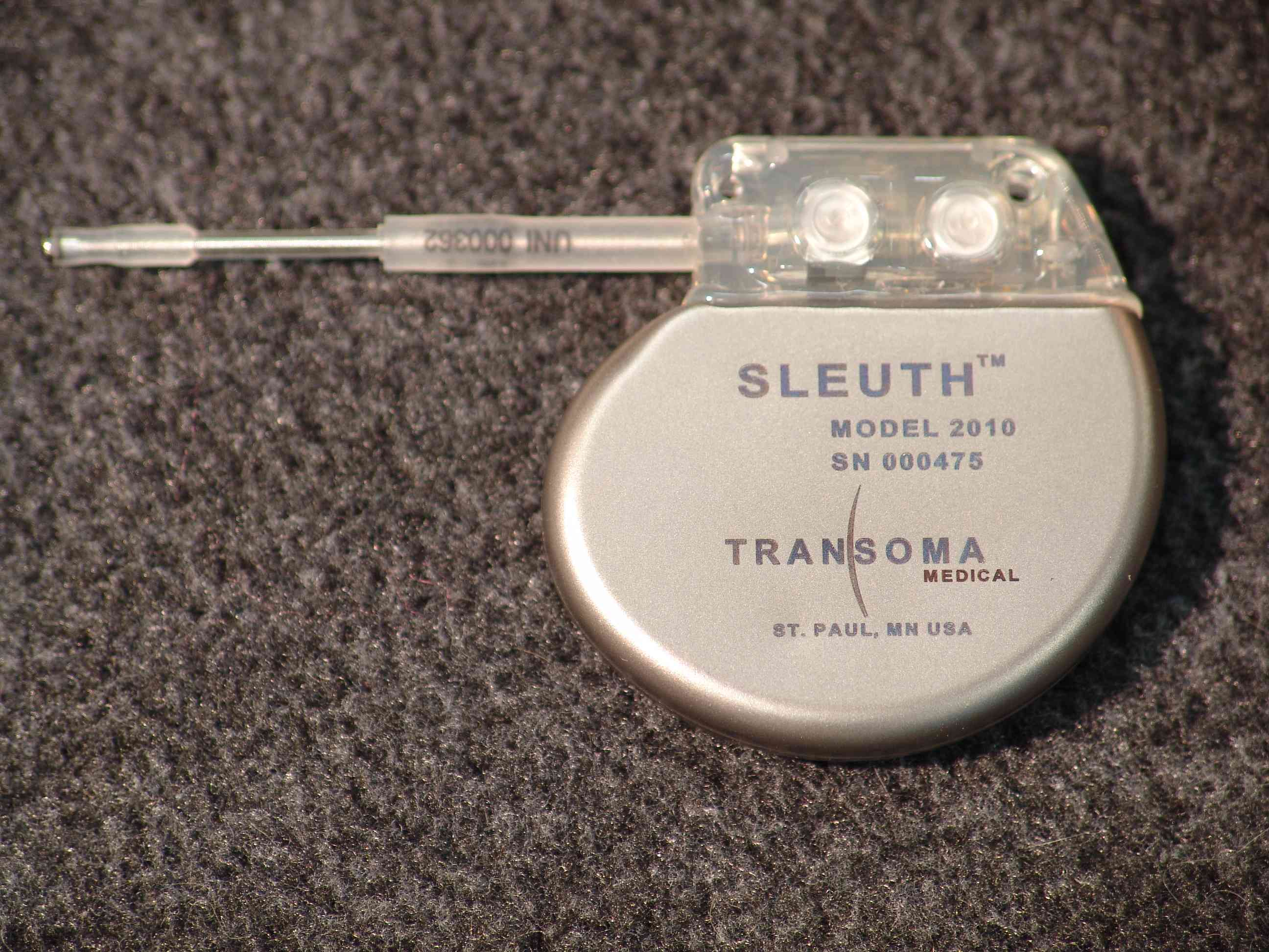
UFYTSIM2010Implanted monitor
Transoma Medical Inc.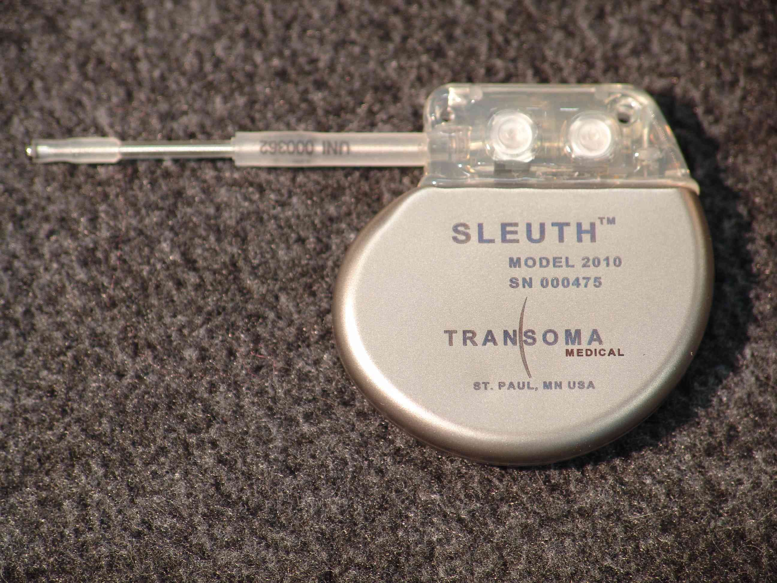
Click to zoom
Application Details
- Equipment Class
- DXX - Part 15 Low Power Communication Device Transmitter
- Date of Grant
- Apr 26, 2007
- Application Purpose
- Original Equipment
- Date of Application
- Mar 10, 2007
- Equipment Note
- Implanted monitor
- Frequency Range
- 916.50000000 - 916.50000000
- Company
- Transoma Medical Inc.
- Country
- United States
Documents & Files
Document Text
Text extracted from the exhibit documents filed with the FCC. Open a document above to read the original.
Users Manual
UnderstandingYour Condition1 Your Implantable ECG MonitoringSystem2 PatientTake-Hom e Bag Co mpo nent s3 Sett ing Up the Monitor ing Systemat Hom e4 If You Expe rienc e Symptoms6 Livin g with Yo ur Mon itoringSystem7 The Acti vator7 Wh en You Pr es s the Act ivate But ton8 Cha rging the Ac tiv ator9 Airplane Mo de9 Tur ning Activator Sounds On and Off10 ECG EventsWithoutSymptoms10 Backlight10 Telep hone Priorit y10 Car e and Cleaning10 Wh en You Tr avel11 Yo ur Pati ent Identification Card11 ImportantMonitoringSystemTip s12 Er ror and Infor mationMessa ges13 Erro r Mes sages13 Inf or mati on Messages14 Fre quentlyAskedQuestions15 OtherConsiderations16 In structionsfor Use Summary22 Ca ution:Federallaw (USA)restrictsthis device to sale by or on the or der of a physician. Note:TheActivator and BaseStation are the propertyof TransomaMedical and mustbe returned to eitheryo ur follow- up doctoror the company foll owinguse. ©2 006 Tra ns oma Med ical Table of Contents FCC ID: UFYTSIM2010 IC:XXXX-TSIM2010 This device complies with Part 15 of the FCC Rules and RSS210 of the Industry Canada Rules. Operation is subject to the following two conditions: (1) this device may not cause harmful interference, and (2) this device must accept any interference received, including interference that may cause undesired operation. The above label information will be located in the instruction manual given to the patient. This sectionprovi des a br ief explanation of com mon con di tions tha t an implantedelec tr ocardi ogram(ECG , also knownas an EKG) monitoringsyste m is designed to monitor. Abnormalhe art rh ythms can be life- thr eateningif they are no t assessedand id entifiedby a tr ained heal th care pro fessional. Most arr hythmiasfall into one of two main categories: •Br adycardiais an abnor mally sl ow or unsteadyheart rhyt hm (usuallyless than 60 beat s per minute)that ma y be acc omp an ied by symptoms such as fainti ng, dizzi ne ss, lethargy,and sho rtne ss of breath. • Tachycar diais an exce ssivelyfast he art rh ythm (usual ly gr eater than 10 0 beats per minute) that may resul t in fib rillat ion, wher e the hea rt beat s so rapidl y that it simply“q uivers.”Fibr il lat ion is the uncoordinatedcontractio n of the heart muscl e that resul ts in a lack of synchronizationbet wee n th e atria (up per heart chambers) and the ventricles (low er heart chambers). Tachycardiamay be acco mpaniedby symptomssuch as fainting,dizziness, fee ling the hea rt beat (palpit atio ns), ch est discom for t or pain (angi na), and shortnessof bre ath. Arr hythmiascan also occurwith outsuch clear symptoms as th ose descri bed above.There may be only subtleindicatorsof an und erlyingheart con dit ion . Ask your doctorfor more infor mation abouttreatmentfor abnormalheart rhythmsan d what you can do to help in the diagnosisof your con diti on. Und ersta nd ing Your Condition 1 ©200 6TransomaMedical Your doc tor has dete rmi ned that an implantedECG monitoring systemwill providead dit ion al infor mationnee ded to asse ss and diagnoseyour condition.The ECG monitoringsy stem is for di ag nostic purpo ses only and doesnot pro vide treatmentof any kind. The implantable monitoring de vice (IM D) con tinu ousl y monitor s the electricalactivit ies of your heart. The IMD is one comp onent in a sy st em that cons ist s of implanted and externalcom pone nts. Wh en the IMD send s in for mationto the Activator,the data ar e securelytransmittedfrom the Act ivato r to the Base Stati on . The Ba se Statio n send s the information over phonelin es to a securedatab ase fo r ev aluation by your doctor. If the Ac tivatoris not with in range of the Base Station(appr oximately 30 feet), the info rmat ion is sto re d fo r later tr ansmi ssion. Your Implantable ECG Moni toringSyst em 2 PatientTa ke-H ome Bag Co mponents The componentsof the mon ito ri ng syste m are pro vided in a Patient Ta ke-H ome Bag for you to set up and use at home. Note:Priorto implan t, your doctoror nu rse sh ouldhave discussedthe implan t procedure, risksandbenefits, the needfor access to a phonelinefor connection to the BaseStation,system setup,andActi vator use and charging requirements. ©2 006 Tra ns oma Med ical 3 Ba se Stat ion Telephone Li ne Y-adapter Telephone Cord Ba se Stat ion PowerSupply Activator PowerSup pl y Activator Pati ent Take-HomeBag SettingUp the MonitoringSy stem at Home It is vitallyimportantthat you set up and acti vate the exte rnal syst em components,beca use th e monitoringsyst em is not oper ation al until the se tasks are comp lete. To set up the monitoringsystem, com plet e the followingste ps: 1. Set up the Base Stat ion (for example, nea r a nightstandor other cent rally locatedpo siti on) so that it will be with in 30 feet of you most of the ti me when you are at home. 2. Plug the yellowBase Stat ion powersupp ly into the yellowBase Stationport and a wall outl et. 3. Plug the telephoneline Y-adapterinto the telephonewall outle t. 4. Plug the blue telep hon e cord into the bl ue Base Stationport an d th e blue Y-adapterpo rt. 5. If de sired, use the othe rY-adapterpor t to connectyour phone. 6. Plug the white Ac tivatorpower suppl y into an AC wall outletnea r your nightstandso th e Ac ti vator ca n chargewhile you sleep. No te:Youmustset up the monitorin g systemco mponents at homefor the ECGmonitoring systemto operate. 4 The Acti va tor also auto mat ically storesand tran smits ECG information(dat a wit hin cr iteria that your do cto r specifiesas well as pe riodic checksof your hea rt rhythm)to a secu re datab ase to aid your do cto r in the diag nosi s of your condition. If you are too far awa y fro m th e Base Station(such as wh en you are away fr om the house), the Activ at or will store EC G informationand auto maticallytransmit it when you returnhom e and are again in rangeof the Base Station. WhenYou Press the Ac tivate Butt on After you press theActi vatebutton,the IM D cont inues to recordanot her two minutes of ECG dat a. K…
Text truncated - open the document above for the full version.
Cover Letter(s)
March 8, 2007 Equipment Authorization Branch Laboratory Division Office of Engineering and Technology Federal Communications Commission 7435 Oakland Mills Road Columbia, MD 21046 Gentlemen: As agent for Transoma Medical, TRP Inc. is herewith submitting an application for certification of a Low Power Transmitter operating on 916 MHz. These devices are very small; have a very low power output generating a low-level electric field that typically communicates with an associated receiver over a range of less than 3 meter. It is implanted with in the body of patients to collect data for later transmission providing a telemetry output of various biophysical parameters such as cardiac condition The implant with leads extended was supported vertically, parallel to the wall, and rotated in this vertical-parallel orientation at least to two positions to place the implant antenna in vertical and horizontal polarizations. For inside-liquid measurements, the transmitter radiated field strength measurements were done with the implant at a maximum depth of 2 centimeters at the closest edges of the device, with the device face parallel to the phantom wall, in a liquid using the parameters as described in OET Bulletin 65 Supplement C for the transmitter fundamental frequency. The identification information will be placed in the instruction manual provided to the patient due to the device being implanted within the body. This protects the patient from possible side effects due to foreign objects such as labels and/or printing inks contaminating the tissue surrounding the implant. Sincerely yours, Phillip Inglis TRP Inc.
Cover Letter(s)
4211 Lexington Avenue North, Suite 2244 T: 651-481-7410 www.transomamedical.com St. Paul, MN 55126 USA F: 651-481-7416 March 6, 2006 Federal Communications Commission Equipment Authorization Branch 7435 Oakland Mills Road Columbia, MD 21046 Request of Confidentiality Transoma Medical, Inc FCC ID: UFYTSIM2010 FCC Part 15 Certification Ladies and Gentlemen, In accordance with 0.459 of CFR 47, Transoma Medical, Inc. hereby requests confidentiality of all Block Diagrams, Circuit Diagram, Parts List, interior photos and Operational Description attachments for the subject application. The interior photos display proprietary information to Transoma which is not released to the public. Further, the interior construction is not available to a purchaser due to the sealed construction of the implant. These documents contain detailed system and equipment description and related information about the product which Transoma Medical, Inc. considers to be proprietary, confidential and a custom design and otherwise would not release to the general public. Since the design is a basis from which future technological products will evolve, Transoma Medical, Inc. considers that this information would be of benefit to its competitors and that the disclosure of the information in these documents would give competitors an unfair advantage in the market. Sincerely, Luke Strawn Senior Electrical Engineer Transoma Medical, Inc. 4211 Lexington Avenue North, Suite 2244 St. Paul, MN 55126 USA
Cover Letter(s)
FCC Response Questions 1. FCC - EMC Test set-up photo is ambiguous – please submit additional photos and/or diagrams showing how device is mounted and describing other proximate or associated apparatus. Transoma – The DUT was placed into a tissue equivalent water sugar mixture used to simulate the attenuation of the human body at 916MHz. This tissue equivalent was contained in a poly-propylene container with a height of 23”, diameter of 16”, and a thickness of 1/8”. The tissue equivalent liquid was filled in the container to a height of 12” so that the DUT was suspended in the tissue equivalent liquid to a depth of 5”, and .5” away from the edge of the container. This is the nominal implant depth of our device. The antenna is the only other apparatus that is located in the area as that is used to measure the field strength. That distance varies from 3, 10, or 30 meters from the center of the table. Page 25 of the EMC Test Report also has a diagram explaining the test configuration 2. FCC - If not in filing already, please provide info about liquid ingredients, mixing procedures, relative permeability, and conductivity Transoma – The tissue recipe was constructed as reported by Hartsgrove et. al. in “Simulated Biological Materials for Electromagnetic Radiation Absorption Studies,” Biloelectromagnetics 8:29-36 (1987) Table Top Ground Floor 80cm 23 inches 12 inches 5 inches DUT The ingredients are listed as percentage by weight - Water - 56%; De-ionized, 16MΩ + resistivity - Salt (NaCl) - .76%; 99 + % Pure Sodium Chloride - Sugar – 41.76%; 98 + % Pure Sucrose - HEC 1.21%; Hydroxyethyl Cellulose - Bactericide .27% The dielectric constant of the tissue equivalent liquid is 56.8, and the Conductivity (S/m) is 1.07. Preparation Methods – - Weigh all ingredients accurately - Heat Water to 40°C - Add salt and bactericide while stirring - Add sugar - Continue to stir at low speed to minimize the amount of air bubbles in the solution. - Add the Hydroxyethyl Cellulose - Remove from heat. - Continue to stir until mixture thickens - Let cool to room temperature. 3. FCC - If not in filing already, please give details about phantom dimensions, wall thickness, material, liquid depth, height above ground. Transoma – The tissue equivalent was contained in a poly-propylene container. The container had a height of about 23”, and a diameter of 16”. The container was about 1/8” thick, and the tissue equivalent was filled in the container until it was about 12” in height. 4. Response to question 4 has been filed as a separate document for which confidentiality is requested.
Cover Letter(s)
4211 Lexington Avenue North, Suite 2244 T: 651-481-7410 www.transomamedical.com St. Paul, MN 55126 USA F: 651-481-7416 March 6, 2006 Federal Communications Commission Equipment Authorization Branch 7435 Oakland Mills Road Columbia, MD 21046 Request of Confidentiality Transoma Medical, Inc FCC ID: UFYTSIM2010 FCC Part 15 Certification Ladies and Gentlemen, In accordance with 0.459 of CFR 47, Transoma Medical, Inc. hereby requests confidentiality of all Block Diagrams, Circuit Diagram, Parts List, interior photos and Operational Description attachments for the subject application. Further, it is requested that Transoma’s response to question 4 contained in FCC application review correspondence be kept confidential. The response contains details of communications protocols that could be of benefit to competitors and is not released to the public. The interior photos display proprietary information to Transoma which is not released to the public. Further, the interior construction is not available to a purchaser due to the sealed construction of the implant. These documents contain detailed system and equipment description and related information about the product which Transoma Medical, Inc. considers to be proprietary, confidential and a custom design and otherwise would not release to the general public. Since the design is a basis from which future technological products will evolve, Transoma Medical, Inc. considers that this information would be of benefit to its competitors and that the disclosure of the information in these documents would give competitors an unfair advantage in the market. Sincerely, Luke Strawn Senior Electrical Engineer Transoma Medical, Inc. 4211 Lexington Avenue North, Suite 2244 St. Paul, MN 55126 USA
ID Label/Location Info
FCC ID: UFYTSIM2010 IC:XXXX-TSIM2010 This device complies with Part 15 of the FCC Rules and RSS210 of the Industry Canada Rules. Operation is subject to the following two conditions: (1) this device may not cause harmful interference, and (2) this device must accept any interference received, including interference that may cause undesired operation. The above label information will be located in the instruction manual given to the patient.
RF Exposure Info
Summary of RF Exposure This device is operated in a manner that ensures the public is not exposed to radio frequency energy levels in excess of the Commission's guidelines. This device is categorically excluded from routine environmental evaluation. This device operates in a portable configuration under 47 CFR 15.249 and is therefore excluded from SAR evaluation based upon 2.1093(c) and its low EIRP (< 1mW). The test data shows a radiated field strength of 530 uV/m at 3 meters. Using empirical formula, this calculates to a maximum EIRP of -40 dBm. Taking into account the negative antenna gain of -22 dBi, the maximum conducted input power to the antenna is - 18 dBm or slightly less than 25 uWatts. For comparison purposes only, a competitors unit similar in construction to this unit was evaluated for SAR. Highest measured SAR value for that unit was 0.08W/kg averaged over 1 gram. The maximum conducted input power to the antenna of that unit was 0.8dBm. Thus the conducted input power to the antenna for Transoma’s unit is some 17 dB lower than the competitive unit. Based on the above, it was not deemed necessary to conduct SAR tests on the unit. Phillip Inglis Consultant to Transoma
Test Report
TÜV AMERICA INC 19333 Wild Mountain Road Taylors Falls MN 55084 Tel: (651) 638-0297 Fax: (651) 638-0298Rev. 092106 TEST RESULT SUMMARY FCC Part 15 Subpart C Section 15.249 Industry Canada RSS-210 Issue 6 Industry Canada RSS-Gen Issue 1 MANUFACTURER'S NAME Transoma Medical NAME OF EQUIPMENT Sleuth MODEL NUMBER(S) TESTED 2010 MANUFACTURER'S ADDRESS 4358 West Round Lake Rd Arden Hills, MN 55112 TEST REPORT NUMBER WC605218.2 TEST DATE(S) 12 September 2006 According to testing performed at TÜV America Inc, the above-mentioned unit is in compliance with the applicable electromagnetic compatibility (EMC) portions of the requirements defined in FCC Part 15 Subpart C Section 15.249 and Industry Canada RSS-210 Issue 6 and RSS-Gen Issue 1. It is the manufacturer's responsibility to assure that additional production units of this model are manufactured with identical electrical and mechanical characteristics. Any modifications necessary for compliance made during testing on the above mentioned date(s) must be implemented in all production units for compliance to be maintained. TÜV America Inc, as an independent testing laboratory, declares that the equipment tested as specified above conforms to the applicable EMC requirements of FCC Part 15 Subpart C “Intentional radiators” Section 15.249 “Operation within the bands 902–928 MHz, 2400–2483.5 MHz, 5725–5875 MHZ, and 24.0–24.25 GHz.” and IC RSS-210 Issue 6 “Low-power Licence-exempt Radiocommunication Devices (All Frequency Bands): Category I Equipment” and RSS-Gen Issue 1 “General Requirements and Information for the Certification of Radiocommunication Equipment”. Date: 21 September 2006 Location: Taylors Falls MN Joe Sausen Joel Schneider USA EMC Senior Technician Senior EMC Engineer Not Transferable TÜV AMERICA INC 19333 Wild Mountain Road Taylors Falls MN 55084 Tel: (651) 638-0297 Fax: (651) 638-0298Rev. 092106 EMC TEST REPORT Test Report File No. : WC605218.2 Date of issue: 21 September 2006 Model / Serial No(s) Tested : 2010 / 001010 Product Type : Sleuth - Implantable Medical Device (IMD) Applicant : Transoma Medical Manufacturer : Transoma Medical License holder : Transoma Medical Address : 4358 West Round Lake Rd Arden Hills, MN 55112 Test Result : Positive Negative Test Project Number References : WC605218.2 Total pages including Appendices : 39 TÜV America Inc reports apply only to the specific samples tested under stated test conditions. It is the manufacturer's responsibility to assure that additional production units of this model are manufactured with identical electrical and mechanical components. TÜV America Inc shall have no liability for any deductions, inferences or generalizations drawn by the client or others from TÜV America Inc issued reports. This report is the confidential property of the client. As a mutual protection to our clients, the public and ourselves, extracts from the test report shall not be reproduced except in full without our written approval. This report shall not be used by the client to claim product endorsement by NVLAP, NIST, or any agency of the US government. TÜV America Inc and its professional staff hold government and professional organization certifications and are members of AAMI, ACIL, AEA, ANSI, IEEE, NARTE, and VCCI. File No. WC605218.2Page 1 of 39 TÜV AMERICA INC 19333 Wild Mountain Road Taylors Falls MN 55084 Tel: (651) 638-0297 Fax: (651) 638-0298Rev. 092106 D I R E C T O R Y Documentation Page(s) Directory 2 Test Regulations, Environmental conditions, Power supply 3 Test Data and Results: FCC IC Field strength of emissions - fundamental 15.249(a) RSS-210 A2.9 4 - 7 Field strength of emissions - harmonics 15.249(a) RSS-210 A2.9 8 - 12 Field strength of emissions - spurious 15.249(d) RSS-210 A2.9 13 - 20 Peak field strength of any emission > 1 GHz 15.249(e) 21 Occupied bandwidth RSS-Gen 4.4.1 22 - 23 Test area diagram 24 Test setup photo(s) 25 - 27 Test Operation Mode, Configuration of the device under test 28 Deviations From Standard, General Remarks, Summary 29 Appendix A Constructional Data Form & Block Diagram 30 - 37 Appendix B Measurement Protocol 38 - 39 Sign Explanations: - not applicable - applicable File No. WC605218.2Page 2 of 39 TÜV AMERICA INC 19333 Wild Mountain Road Taylors Falls MN 55084 Tel: (651) 638-0297 Fax: (651) 638-0298Rev. 092106 EMC TEST REGULATIONS: The tests were performed according to the following regulations : - EN 55014-2: 1997 + Amendment A1: 2001 - Category __ - EN 55024: 1998 + Amendments A1: 2001 + A2: 2003 - EN 60601-1-2: 2001 - EN 61000-6-1: 2001 - EN 61000-6-2: 2001 - EN 61326: 1997 + Amendments A1: 1998 + A2: 2001 + A3: 2003 - EN 61800-3: 1996 + Amendment A11: 2000 - ETS 300 683: 1997 - ETSI EN 301 489-3 V1.4.1: 2002 - EN 300 330-2 V1.1.1 (2001-06) - FCC Part 15 Subpart C Section 15.249 - FCC Part 15 Subpart C Section 15.207 - IC RSS-210 Issue 6 - IC RSS-Gen Issue 1 - IC RSS-Gen Issue 1 ENVIRONMENTAL CONDITIONS IN THE LAB Actual Temperature: : 23 °C Atmospheric pressure : 99 kPa Relative Humidity : 45 % POWER SUPPLY UTILIZED Power supply system : 3 VDC battery File No. WC605218.2Page 3 of 39 TÜV AMERICA INC 19333 Wild Mountain Road Taylors Falls MN 55084 Tel: (651) 638-0297 Fax: (651) 638-0298Rev. 092106 Field strength of emissions - fundamental FCC 15.249(a), IC RSS-210 A2.9 Test summary The requirements are: - MET - NOT MET Minimum margin of compliance is 32.32 dB at 916.479 MHz Test location - Wild River Lab Large Test Site (Open Area Test Site) - Wild River Lab Small Test Site (Open Area Test Site) Test equipment TUV ID Model Number Manufacturer Description Serial Number Cal Due 3204 EM-6917B Electro-Metrics Biconicalog Periodic 102 19-Oct-06 3847 ZHL-1042J Mini-Circuits Preamplifier 10 - 3000 MHz 0607 Code B 2690 8566B Hewlett-Packard Spectrum Analyzer 2430A00930 12 May 07 2673 85662A Hewlett-Packard Analyzer Display 2152A03687 12 May 07 2684 85650A Hewlett-Packard Quasi-Peak Adapter 2521A01006 15 Mar 07 Cod…
Text truncated - open the document above for the full version.
Test Setup Photos
TÜV AMERICA INC 19333 Wild Mountain Road Taylors Falls MN 55084 Tel: (651) 638-0297 Fax: (651) 638-0298Rev. 092106 Test-setup photo(s): Radiated Emissions File No. WC605218.2Page 26 of 39
Contact Information
Applicant
Perry Mills(Vice President and Chief Technology Officer)
Technical Contact
TRP IncPhillip Inglis
[email protected]410 531 3439
14085 Howard Rd · Dayton, Maryland · United States
Test Firm
PCTEST Engineering Laboratory, Inc.Randy Ortanez
Technical Specifications
| # | Rule Parts | Frequency Range | Power Output |
|---|---|---|---|
| 1 | 15C | 916.5 MHz - 916.5 MHz | - |
Other Applications from Transoma Medical Inc.
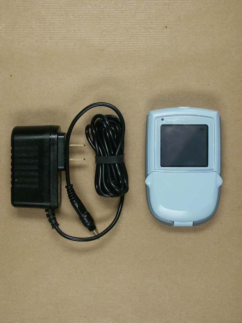
UFYTSAV4000
Feb 27, 2007Activator Model 4000
Equipment Class
CYY - Communications Receiver used w/Pt 15 Transmitter