UGDKBPANELG2ESP KB Panel
ESP Systems, LLC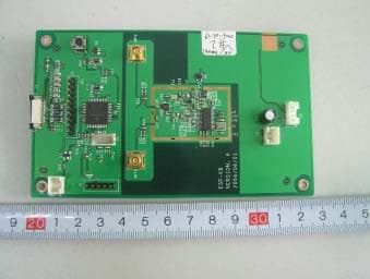
Click to zoom
Application Details
- Equipment Class
- DXX - Part 15 Low Power Communication Device Transmitter
- Date of Grant
- Aug 02, 2006
- Application Purpose
- Original Equipment
- Date of Application
- Aug 01, 2006
- Equipment Note
- ESP KB Panel
- Frequency Range
- 902.30000000 - 927.54300000
- Company
- ESP Systems, LLC
- Country
- United States
Documents & Files
Document Text
Text extracted from the exhibit documents filed with the FCC. Open a document above to read the original.
Users Manual
MANAGERS USER’S GUIDE ESP Systems Manager User Manual 1 Introduction Manager User Manual ESP Systems™ is a wireless network that seamlessly and instantly connects the guest with the servers, and the servers with the host, bar, kitchen, and managers. This is the first Guest Customized Service System™ on the market. ESP will change the face of your service model. Servers will take fewer steps, guests will be happier and tell their friends, and managers will now have real time performance data on their service model. Never before have managers been able to know exactly when their service model is breaking down. Website: www.espsystems.net Support Center Number: ESP Systems 401 N. Tryon St. Transamerica Square 10 th Floor Suite 1085 Charlotte, NC 28202 ESP SYSTEM SUPPORT ESP System CONTACTS: Devin Green [email protected] CEO Kristen Worner [email protected] VP-Client Satisfaction Danica Revelo [email protected] Service Specialist Content Manager User Manual Introduction to ESP ESP Systems Manager User Manual 2 ESP Contact Information 1 ESP Equipment Support Center 1 FAQ’s: Frequently Asked Questions 3 Equipment Host Linc Use and Maintenance 4 Host-Linc set up for the shift/day 4 ESP Hub Use and Maintenance 5 ESP Key Use 5 ESP Key Ordering Procedures 5 ESP Watch Use and Maintenance 5 ESP Hub Charging 6 ESP Watch Charging 7 ESP Kitchen-Linc Use and Maintenance 8 ESP Bar-Linc Use and Maintenance 8 Alerts and ESP’s Procedures and Responses Server/Host/Busser ESP’s 9 Manager Alerts 10 Host-Linc 11 Setting up the Alerts for a Day/Shift 12 ESP Data Reporting 14 Manager Keys to Success with an ESP Table Turn 18 Troubleshooting the system Host-Linc 19 ESP Watches 21 ESP Hubs 23 ESP Keys 25 ESP Kitchen-Linc 26 ESP Bar-Linc 29 ESP Hub and Watch Chargers 32 LMS 34 Setting up for Product Updates 40 INTRODUCTORY FAQ’S What is ESP? ESP Systems Manager User Manual 3 Definition of ESP: Extra Sensory Perception. The 6 th sense, the ability to read peoples’ minds. ESP is the first Guest Customized Service System™. It streamlines the service model, through a series of Alerts that come. Training ESP - What is ESP E-Learning? ESP has designed a series of courses to train you and your associates prior to you ever having ESP installed in your building. This way you can be prepared! Here is how to access the ESP E-Learning Site. Log onto http://projects.getthinking.com Enter the user name: The user name is: Enter the password: The password is: This will bring you to a black screen with a small computer icon on it. On this screen go to the taskbar across the top and click on Tools. Click on the pop up blocker and make sure the pop-up blocker is turned on (blocking the pop-up’s) Then click on the computer icon and the program will run. This course has to be taken from a high speed internet location. Otherwise the program will not load! For best retention the course should be taken prior early in the training. Component Input a picture of the Host-Linc ESP Systems Manager User Manual 4 Entering the Roster Input a picture of entering the roster here. Populate a Floor Plan Input a picture of a floor plan and dragging and dropping Changing a Floor Plan Insert a picture of how to change a floor plan Reassigning a Table Insert a picture of how to change a floor plan Enter Streaming Messages on the Hub Insert a picture of how to enter streaming messages Enter Alert Setting Levels Insert a picture of how to enter alert Settings Brief outline of how to decide what alert settings should be ESP HUB TIPS Place on center or front edge of table for ease of Shooting the Hub. MAINTENANCE ESP Systems Manager User Manual 5 Charge Weekly for best battery life. Store extra Hubs in a charger as back up. CLEANING Wash frequently with soap and water. The hubs are waterproof. Be carefull not to scratch the lenses. ESP Key Insert a picture of the key Insert ordering procedures for the keys Insert Tips on storing the keys ESP Watch Insert a GOOD picture of the watch and outline the Columns and what the different functions are. ESP Hub Chargers ESP Systems Manager User Manual 6 ESP Watch Chargers ESP Systems Manager User Manual 7 ESP KITCHEN-LINC TIPS ESP Systems Manager User Manual 8 Every FOH employee needs to know how to use the Kitchen-Linc. Use the Kitchen-Linc with EVERY table, to capture good data and build good habits. MAINTENANCE No on-going maintenance required. If it ever needs to be re- set, unplug it for a minute and plug it back in. CLEANING Spray with hose or clean with water. No abrasives. Clean daily. ESP BAR – LINC TIPS Bartenders should use the Bar-Linc with EVERT order. This will capture good performance data and build good habits. . MAINTENANCE No ongoing maintenance required. To reset unplug for 1 minute and plug back in. CLEANING Spray off with hose, or clean with water. No abrasives. Clean daily. LMS: Learning Management System Insert info here ESP E-Learning: Included above? All these alerts will appear on the Host-Linc, some will also appear on the Managers watch. You now have two tools to assist you in identifying holes in your service model. FOH Managers can immediately re-position the team to address the situation. Hosts will be relied on to assist in reacting to these alerts. ESP Systems Manager User Manual 9 Associate ESPs ESP DEFINITION RESPONSE I’VE BEEN SAT You’ve been sat! Get to that table quickly and welcome them to the restaurant. Deliver the WOW Step. GUEST ESP Your Guest Needs You! Quickly check in with the table by recognizing that they have ESP’d you. DRINK READY/RUN ESPs you that your drinks are up. When the image is reversed (light on dark), your drinks have been run. Run your drinks when they are ready. Return to table that has drinks and continue the next step of service. FOOD READY/RUN ESPs you that your food is ready or has been run (if a reversed light on dark image shows). Run your food when it is ready. Quality Check the table when the food is run. 911 911 will appear u…
Text truncated - open the document above for the full version.
Cover Letter(s)
ESP Systems, LLC FCC Confidential Authorization Date: July 25, 2006 FEDERAL COMMUNICATIONS COMMISSIONS Authorization and Evaluation Division 7435 Oakland Mills Road Columbia, MD 21046 Confidentiality Request regarding application for certification of FCC ID: (UGDKBPANELG2 ). Pursuant to Sections 0.457 and 0.459 of the Commission’s Rules, we hereby request confidential treatment of information accompanying this application as outlined below: (User Manual, Schematic, Block Diagram, Circuit description) The above materials contain trade secrets and proprietary information not customarily released to the public. The public disclosure of these materials may be harmful to the applicant and provide unjustified benefits to its competitors. The applicant understands that pursuant to Section 0.457 of the Rules, disclosure of this application and all accompanying documentation will not be made before the date of the Grant for this application. Sincerely Yours, Signature: Typed or Printed Name: Title: Company Name: ESP Systems, LLC Form 05
External Photos
External Photos EUT- Front View EUT- Back View EUT-Adapter View
ID Label/Location Info
ID Label Label FCC ID: UGDKBPANELG2 This device complies with part 15 of the FCC Rules. Operation is subject to the following two conditions: (1) This device may not cause harmful interference, and (2) this device must accept any interference received, including interference that may cause undesired operation.
ID Label/Location Info
ID Label/Location Label Location Information Specifications: Text is Black or white in color and is left justified. Labels are printed in indelible ink on permanent adhesive backing or silk-screened onto the EUT or shall be affixed at a conspicuous location on the EUT. Refer to the below arrow.
Internal Photos
Internal Photos EUT- Uncovered View EUT- Control Board Top View EUT-Inside View (2) EUT-PCB Top View EUT- Control Board Bottom View EUT- LCD Board Top View EUT- LCD Board Bottom View
Test Report
Note: The test report is specially limited to the above company and this particular sample only. It may not be duplicated without prior written consent of Bay Area Compliance Lab Corp. (ShenZhen). This report must not be used by the client to claim product certification, approval, or endorsement by NVLAP, NIST or any agency of the US Government. FCC PART 15.249 EMI MEASUREMENT AND TEST REPORT For ESP Systems, LLC 401 N.Tryon St-10th Floor, Charlotte, NC FCC ID: UGDKBPANELG2 July 26, 2006 This Report Concerns: Original Report Equipment Type: ESP KB Panel Test Engineer: Deny Xiong Louise Lu Report No.: RSZ06071002 Test Date: July 11, 2006 Reviewed By: Boni Baniqued Prepared By: Bay Area Compliance Lab Corp. (ShenZhen) 6/F, the 3rd Phase of WanLi Industrial Building, ShiHua Road, FuTian Free Trade Zone, ShenZhen, Guangdong 518038, P.R.China Tel: +86-755-33320018 Fax: +86-755-33320008 ESP Systems, LLC FCC ID: UGDKBPANELG2 Report # RSZ06071002 Page 2 of 22 FCC PART 15.249 Report TABLE OF CONTENTS GENERAL INFORMATION.......................................................................................................................................3 PRODUCT DESCRIPTION FOR EQUIPMENT UNDER TEST (EUT) .....................................................................................3 OBJECTIVE...................................................................................................................................................................3 RELATED SUBMITTAL(S)/GRANT(S).............................................................................................................................3 TEST METHODOLOGY..................................................................................................................................................3 TEST FACILITY.............................................................................................................................................................3 EXTERNAL I/O CABLE..................................................................................................................................................4 SYSTEM TEST CONFIGURATION ..........................................................................................................................5 JUSTIFICATION.............................................................................................................................................................5 EQUIPMENT MODIFICATIONS.......................................................................................................................................5 CONFIGURATION OF TEST SETUP.................................................................................................................................6 BLOCK DIAGRAM OF TEST SETUP................................................................................................................................6 SUMMARY OF TEST RESULTS...............................................................................................................................7 §15.203 - ANTENNA REQUIREMENT......................................................................................................................8 STANDARD APPLICABLE..............................................................................................................................................8 ANTENNA CONNECTOR CONSTRUCTION......................................................................................................................8 §15.207 - CONDUCTED EMISSION ..........................................................................................................................9 MEASUREMENT UNCERTAINTY....................................................................................................................................9 EUT SETUP..................................................................................................................................................................9 EMI TEST RECEIVER SETUP.......................................................................................................................................10 TEST EQUIPMENT LIST AND DETAILS.........................................................................................................................10 TEST PROCEDURE......................................................................................................................................................10 TEST RESULTS SUMMARY..........................................................................................................................................10 TEST DATA................................................................................................................................................................11 PLOT(S) OF TEST DATA..............................................................................................................................................11 §15.205 §15.209(A) §15.249(A) - RADIATED EMISSION ......................................................................................14 MEASUREMENT UNCERTAINTY..................................................................................................................................14 EUT SETUP................................................................................................................................................................14 EMI TEST RECEIVER SETUP.......................................................................................................................................15 TEST EQUIPMENT LIST AND DETAILS.........................................................................................................................15 TEST PROCEDURE......................................................................................................................................................15 CORRECTED AMPLITUDE & MARGIN CALCULATION..…
Text truncated - open the document above for the full version.
Test Setup Photos
Test Setup Photos Conducted Emission - Front View Conducted Emission - Side View Transmitting Mode: Radiated Emission - Front View (up to 1GHz) Transmitting Mode: Radiated Emission - Rear View (up to 1GHz) Transmitting Mode: Radiated Emission – Front View (Above 1GHz) Transmitting Mode: Radiated Emission – Rear View (Above 1GHz)
Contact Information
Applicant
Todd A Binkowski(Chief Operating Officer)
Test Firm
Bay Area Compliance Laboratory Corp. (Shenzhen)John Chan
Technical Specifications
| # | Rule Parts | Frequency Range | Power Output |
|---|---|---|---|
| 1 | 15C | 902.3 MHz - 927.543 MHz | - |
Other Applications from ESP Systems, LLC
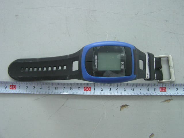
UGDWATCHG2
Mar 03, 2007ESP Watch
Equipment Class
DXX - Part 15 Low Power Communication Device Transmitter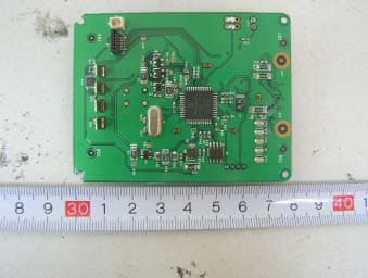
UGDHUBG2
Aug 02, 2006ESP Hub
Equipment Class
DXX - Part 15 Low Power Communication Device Transmitter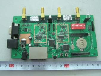
UGDCENTRALUNITG2
Aug 02, 2006ESP Central Unit
Equipment Class
DXX - Part 15 Low Power Communication Device Transmitter