UGX-X10001X1.9GHz Cordless VOIP Phone
American Telecom Services, Inc.
Click to zoom
Application Details
- Equipment Class
- PUB - Part 15 Unlicensed PCS Base Station
- Date of Grant
- Nov 02, 2006
- Application Purpose
- Original Equipment
- Date of Application
- Nov 02, 2006
- Equipment Note
- 1.9GHz Cordless VOIP Phone
- Frequency Range
- 1921.53600000 - 1928.44800000
- Country
- United States
Documents & Files
Document Text
Text extracted from the exhibit documents filed with the FCC. Open a document above to read the original.
Users Manual
X10001X VoIP GATWAY User’s Manual X10001X VoIP GATWAY User’s Manual 1 2 User’s Manual for the X10001X For use with Internet Phone service by SunRocket To enjoy all the benefits of this product, please review the information contained in this manual Introduction.............................................................................................................................................. 3 Hardware Overview............................................................................................................................. 3 Software Overview............................................................................................................................... 3 IVR Interface for The X10001X............................................................................................................... 4 Quick Guide of X10001X Network setup automatically........................................................................... 6 X10001X Network Setup Automatically Step By Step............................................................................. 7 Ethernet Adapter Detection .................................................................................................................. 8 Network Environment Detection .......................................................................................................... 9 DHCP User Network Environment:.................................................................................................... 10 PPPoE User Network Environment: ................................................................................................... 11 Fix IP User Network Environment: .................................................................................................... 12 X10001X Network Settings Test: ....................................................................................................... 13 Network Settings was unsuccessful: ................................................................................................... 14 X10001X Reboot............................................................................................................................... 15 The Installation is Complete ............................................................................................................... 16 Setup the X10001X by Web Browser..................................................................................................... 17 System Information ............................................................................................................................ 17 Single computer environment quick setup.......................................................................................... 19 Setting Up the TCP/IP Protocol.......................................................................................................... 20 General Configuration ........................................................................................................................ 23 DHCP/Cable Users:............................................................................................................................ 23 Fixed IP Users:................................................................................................................................... 23 ADSL Users (PPPoE dial-up connection): .......................................................................................... 24 Multiple computers environment quick setup:.................................................................................... 26 Phone Book........................................................................................................................................ 28 Phone Settings.................................................................................................................................... 28 Call Forwarding:................................................................................................................................ 28 Volume Settings: ................................................................................................................................ 29 T.38 FAX Settings.............................................................................................................................. 30 Network ............................................................................................................................................. 32 SIP Settings........................................................................................................................................ 34 System Auth....................................................................................................................................... 35 Save Change & Reboot...................................................................................................................... 35 Update................................................................................................................................................ 36 How to make a phone call ...................................................................................................................... 37 X10001X VoIP GATWAY User’s Manual X10001X VoIP GATWAY User’s Manual 3 4 Introduction This user’s manual is for the ATS X10001X. It will explain the IVR instruction, web configuration and command line configuration for the X10001X. Before using the X10001X, some setup processes are required to make the X10001X work properly. Please refer to the Setup Menu for further information. Hardware Overview The X10001X has the following interfaces for Networking, telephone, LED indication, and power connection. 1.1.1 Two RJ-45 Networking interface, these two interfaces support 10/100Mps Fast Ethernet. You can connect one RJ-45 Fast Ethernet port to your internet connection and connect the other one to your computer. 1.1.2 One RJ-11 Type analog te…
Text truncated - open the document above for the full version.
External Photos
External Photos EUT – Top View EUT – Bottom View
ID Label/Location Info
ID Label Label
ID Label/Location Info
ID Label/Location Label Location Information Specifications: Text is Black or white in color and is left justified. Labels are printed in indelible ink on permanent adhesive backing or silk-screened onto the EUT or shall be affixed at a conspicuous location on the EUT. Refer to the below arrow.
Internal Photos
Internal Photos EUT – Inside View (1) EUT – Inside View (2) EUT – Inside View (3) EUT – PCB 1 Front View EUT – PCB 1 Rear View EUT – PCB 2 Front View EUT – PCB 2 Uncover of Shield Front View EUT – PCB 2 Rear View
RF Exposure Info
§ 15.319 (i) - RF RADIATION EXPOSURE Limit According to §1.1307(b)(1), systems operating under the provisions of this section shall be operated in a manner that ensures that the public is not exposed to radio frequency energy level in excess of the Commission’s guidelines. According to §1.1310 and §2.1091 RF exposure is calculated. Limits for Maximum Permissible Exposure (MPE) Frequency Range (MHz) Electric Field Strength (V/m) Magnetic Field Strength (A/m) Power Density (mW/cm2) Averaging Time (minute) Limits for General Population/Uncontrolled Exposure 0.3-1.34 614 1.63 *(100) 30 1.34-30 842/f 2.19/f *(180/f\2\) 30 30-300 27.5 0.073 0.2 30 300-1500. / / f/1500 30 1500-100,000. / / 1.0 30 f = frequency in MHz * = Plane-wave equivalent power density Test Data Predication of MPE limit at a given distance Equation from page 19 of OET Bulletin 65, Edition 97-01 where: S = power density (in appropriate units, e.g. mW/cm2) P = power input to the antenna (in appropriate units, e.g., mW) . G = power gain of the antenna in the direction of interest relative to an isotropic radiator, the power gain factor, is normally numeric gain. R = distance to the center of radiation of the antenna (appropriate units, e.g., cm) Result: Pass Maximum peak output power at antenna input terminal: 14.35(dBm ) Maximum peak output power at antenna input terminal: 27.227 (mW) Predication frequency: 1924.992 (MHz) Antenna Gain (typical): 0 dBi Limits for Maximum Permissible Exposure Power density: 1 (mW/cm 2 ) The minimum safety distance: 1.47cm.
Test Report
Note: The test report is specially limited to the above company and this particular sample only. It may not be duplicated without prior written consent of Bay Area Compliance Lab Corp. (ShenZhen). This report must not be used by the client to claim product certification, approval, or endorsement by NVLAP, NIST or any agency of the US Government. FCC PART 15.323 EMI MEASUREMENT AND TEST REPORT For American Telecom Services, Inc. 2466, Peck Road, City of Industry, CA 90601, U.S.A FCC ID: UGX-X10001X September 18, 2006 This Report Concerns: Original Report Equipment Type: 1.9GHZ CORDLESS VOIP PHONE Test Engineer: Merry Zhao Report No.: RSH06082201 Test Date: August 31, 2006-September 2, 2006 Reviewed By: EMC Manager: Boni Baniqued Prepared By: Bay Area Compliance Lab Corp. (ShenZhen) 6/F, the 3rd Phase of WanLi Industrial Building, ShiHua Road, FuTian Free Trade Zone, ShenZhen, Guangdong 518038, P.R.China Tel: +86-755-33320018 Fax: +86-755-33320008 American Telecom Services, Inc. FCC ID: UGX-X10001X Report # RSH06082201 Page 2 of 41 FCC Part 15.323 Test Report TABLE OF CONTENTS GENERAL INFORMATION.......................................................................................................................................4 PRODUCT DESCRIPTION FOR EQUIPMENT UNDER TEST (EUT) ....................................................................................4 OBJECTIVE...................................................................................................................................................................4 RELATED SUBMITTAL(S)/GRANT(S).............................................................................................................................4 TEST METHODOLOGY..................................................................................................................................................4 TEST FACILITY.............................................................................................................................................................4 HOST SYSTEM CONFIGURATION LIST AND DETAILS....................................................................................................5 LOCAL SUPPORT EQUIPMENT LIST AND DETAILS........................................................................................................5 EXTERNAL I/O CABLE..................................................................................................................................................5 SYSTEM TEST CONFIGURATION ..........................................................................................................................6 JUSTIFICATION.............................................................................................................................................................6 EUT EXERCISE SOFTWARE..........................................................................................................................................6 SPECIAL ACCESSORIES.................................................................................................................................................6 EQUIPMENT MODIFICATIONS.......................................................................................................................................6 CONFIGURATION OF TEST SETUP.................................................................................................................................7 BLOCK DIAGRAM OF TEST SETUP................................................................................................................................7 SUMMARY OF TEST RESULTS ...............................................................................................................................8 §15.317&15.203 - ANTENNA REQUIREMENT .......................................................................................................9 STANDARD APPLICABLE..............................................................................................................................................9 §15.315&15.207 - CONDUCTED EMISSION ..........................................................................................................10 MEASUREMENT UNCERTAINTY..................................................................................................................................10 EUT SETUP................................................................................................................................................................10 EMI TEST RECEIVER SETUP.......................................................................................................................................11 TEST EQUIPMENT LIST AND DETAILS.........................................................................................................................11 TEST PROCEDURE......................................................................................................................................................11 TEST RESULTS SUMMARY..........................................................................................................................................11 TEST DATA................................................................................................................................................................12 TEST PLOTS................................................................................................................................................................12 §15.319 (G) - RADIATED EMISSION ......................................................................................................................15 MEASUREMENT UNCERTAINTY..................................................................................................................................15 EUT SETUP...................................................................................................................................…
Text truncated - open the document above for the full version.
Test Setup Photos
Test Setup Photos Conducted Emission – Front View Conducted Emission – Rear View Radiated Emission – Front View (30-1000MHz) Radiated Emission – Rear View (30-1000MHz) Radiated Emission - Front View (Above 1000MHz) Radiated Emission - Rear View (Above 1000MHz)
Contact Information
Applicant
Adam Somer
Test Firm
Bay Area Compliance Laboratory Corp. (Shenzhen)John Chan
Technical Specifications
| # | Rule Parts | Frequency Range | Power Output | Tolerance |
|---|---|---|---|---|
| 1 | 15D | 1.92 GHz - 1.93 GHz | 28.97 mW | 1.8000000000 ppm |
Other Applications from American Telecom Services, Inc.

UGX-X10002X
Nov 06, 20061.9GHZ Cordless VOIP PHONE
Equipment Class
PUE - Part 15 Unlicensed PCS portable Tx held to ear
UGX-J2200
Oct 18, 2006VoIP
Equipment Class
JBP - Part 15 Class B Computing Device Peripheral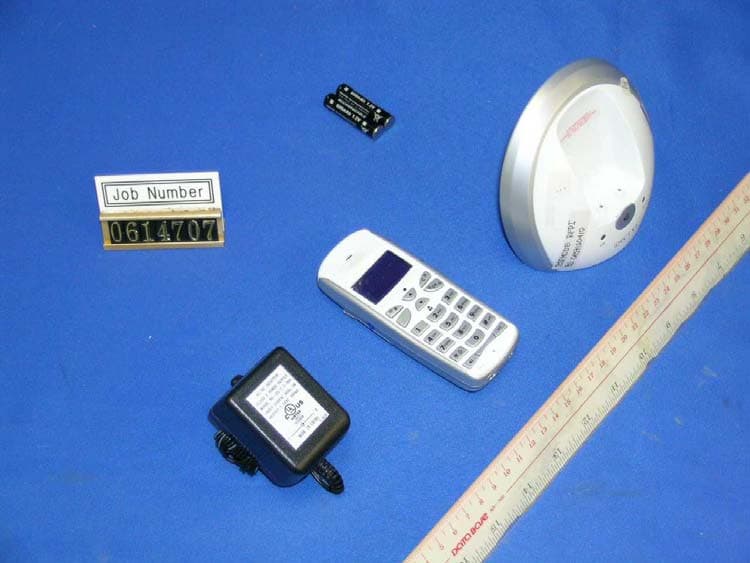
UGXRA2184BBH
Sep 03, 2006Digital Modulation Cordless Phone - Handset
Equipment Class
PUE - Part 15 Unlicensed PCS portable Tx held to ear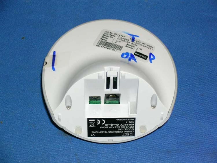
UGXRA2184BB
Aug 15, 2006Digital Modulation Cordless Phone - Base Unit
Equipment Class
PUB - Part 15 Unlicensed PCS Base Station