UH7EBCU01Device for remote control of medical devices
Allergan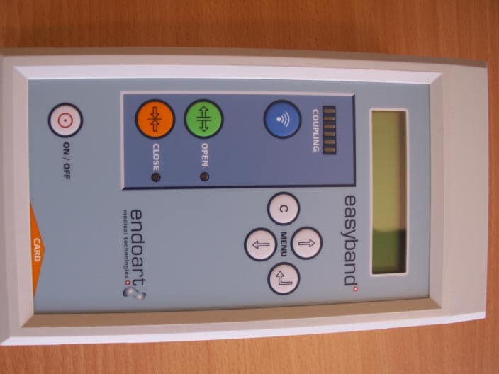
Click to zoom
Application Details
- Equipment Class
- DXT - Part 15 Low Power Transceiver, Rx Verified
- Date of Grant
- Sep 06, 2006
- Application Purpose
- Original Equipment
- Date of Application
- Sep 06, 2006
- Equipment Note
- Device for remote control of medical devices
- Frequency Range
- 27.00000000 - 27.00000000
- Company
- Allergan
- Country
- Switzerland
Documents & Files
Document Text
Text extracted from the exhibit documents filed with the FCC. Open a document above to read the original.
Users Manual
fkpqor`qflkp=clo=rpb fkpqor`qflkp=clo=rpbfkpqor`qflkp=clo=rpb fkpqor`qflkp=clo=rpb= = EndoArt SA, PSE-B CH 1015 Lausanne ïïïKÉåÇç~êíKÅçã= = = == = = == = b~ëóÄ~åÇ b~ëóÄ~åÇb~ëóÄ~åÇ b~ëóÄ~åÇ ∆ ∆∆ ∆ =`çåíêçä=råáí= =`çåíêçä=råáí==`çåíêçä=råáí= =`çåíêçä=råáí== == = = == = 0123 = = fkpqor`qflkp=clo=rpb fkpqor`qflkp=clo=rpbfkpqor`qflkp=clo=rpb fkpqor`qflkp=clo=rpb 10030-1-1 IFU EB CU.doc 1 of 42 ` ` ç ç å å í í É É å å í í ë ë = = 1 GENERAL INFORMATION ..................................................3 1.1 Contents of the Carrying Case..............................................3 1.2 Aim of the Device ..................................................................4 2 GENERAL PRINCIPLES OF ADJUSTMENT ......................5 3 PRECAUTIONS AND WARNINGS ......................................7 3.1 User Training ........................................................................7 3.2 Band Adjustment...................................................................7 3.3 Electromagnetic Interactions.................................................8 3.4 Control Unit Handling ............................................................9 3.5 Sterility ..................................................................................9 4 DEVICE HANDLING...........................................................10 4.1 Description ..........................................................................10 4.1.1 Description of front face..........................................................................................10 4.1.2 Description of connection face................................................................................11 4.1.3 Information given to the user ..................................................................................11 4.2 Storage, Cleaning, Maintenance and Disposal ...................12 4.2.1 Storage ...................................................................................................................12 4.2.2 Cleaning..................................................................................................................12 4.2.3 Maintenance and repair ..........................................................................................12 4.2.4 Disposal ..................................................................................................................12 5 ADJUSTMENT PROCEDURE............................................13 5.1 Patient Monitoring ...............................................................13 5.2 Control Unit Preparation......................................................13 5.3 Coupling with the Implant Antenna .....................................14 5.4 Band Adjustment.................................................................17 5.5 End of Adjustment Procedure .............................................19 fkpqor`qflkp=clo=rpb fkpqor`qflkp=clo=rpbfkpqor`qflkp=clo=rpb fkpqor`qflkp=clo=rpb 10030-1-1 IFU EB CU.doc 2 of 42 6 BATTERY ........................................................................... 20 6.1 Battery Level Indications..................................................... 20 6.2 Recharging the Battery, Using with the External Power Supply ................................................................................ 20 7 SPECIAL MENUS .............................................................. 21 7.1 Navigation in the Menus ..................................................... 21 7.1.1 ↵ key (ENTER key) ................................................................................................21 7.1.2 C key (CORRECTION key).....................................................................................21 7.1.3 ↑ key (UP key)........................................................................................................21 7.1.4 ↓ key (DOWN key) .................................................................................................22 7.1.5 Example of use of special menus ...........................................................................22 7.2 User Menu .......................................................................... 23 7.2.1 Battery Status .........................................................................................................23 7.2.2 Implant ID................................................................................................................23 7.2.3 No Card Mode.........................................................................................................23 7.2.4 Firmw. Version ........................................................................................................23 7.3 Configuration Menu ............................................................ 24 7.3.1 LCD Contrast ..........................................................................................................24 7.3.2 Buzzer Volume........................................................................................................24 7.3.3 Backlight Off Delay .................................................................................................24 7.3.4 Backlight Level ........................................................................................................24 7.3.5 Backlight On/Off......................................................................................................24 7.3.6 Power Off Delay......................................................................................................25 7.3.7 Set Default Value ....................................................................................................25 7.4 No Card Mode .................................................................... 25 7.4.1 Warnings .................................................................................................................25 7.4.2 Adjustment in no card mode ...................................................................................26 8 MEANING…
Text truncated - open the document above for the full version.
Users Manual
fkpqor`qflkp=clo=rpb fkpqor`qflkp=clo=rpbfkpqor`qflkp=clo=rpb fkpqor`qflkp=clo=rpb 10030-1-1 IFU EB CU.doc 23 of 42 →Backlight Delay Backlight Level 8. The change is now effective. Press the ↵ key to enter the display backlight delay menu. The display reads: BackLight Delay 130 [s] 9. Press the key C to exit from the menu. The display reads: →Backlight Delay Backlight Level 10. Press the C key to exit from the configuration menu. The display reads: User Menu → Config Menu 11. Press the C key to exit from the special menus. The display returns to its initial display. TKO TKOTKO TKO= == = rëÉê=jÉåì rëÉê=jÉåìrëÉê=jÉåì rëÉê=jÉåì= == = 7.2.1 Battery Status This menu displays the battery charge level represented on a 5 bar scale: BATTERY LEVEL █████ 7.2.2 Implant ID This menu displays the implant identification number recorded in the implant. This is a manufacturer code and it is not the same as the serial number. EASYBAND ID: XXXXXXXX 7.2.3 No Card Mode This mode is used to make an adjustment without a microchip card. Its use is described in chapter 7.4. 7.2.4 Firmw. Version This menu indicates the firmware version implemented on the Easyband ® Control Unit: FCU X.XXX / 200X (c) ENDOART – CH fkpqor`qflkp=clo=rpb fkpqor`qflkp=clo=rpbfkpqor`qflkp=clo=rpb fkpqor`qflkp=clo=rpb 10030-1-1 IFU EB CU.doc 24 of 42 TKP TKPTKP TKP= == = `çåÑáÖìê~íáçå=jÉåì `çåÑáÖìê~íáçå=jÉåì`çåÑáÖìê~íáçå=jÉåì `çåÑáÖìê~íáçå=jÉåì= == = 7.3.1 LCD Contrast This menu is used to change the display contrast. This parameter corresponds by default to 3 bars out of 5: LCD Contrast ███__ 7.3.2 Buzzer Volume This menu is used to change the sound level of the buzzer signals. By default, this parameter corresponds to 2 bars out of 3: Buzzer Volume ██_ The user should set these buzzer signals to an audible level. 7.3.3 Backlight Off Delay The display backlight switches off after a certain time to preserve the battery level. This menu is used to change this time delay, see 7.1.5 (example of use of special menus). By default the time is 20 seconds. It can be adjusted between 1 second and 999 seconds: BackLight Delay XXX [s] 7.3.4 Backlight Level This menu is used to change the display backlight intensity. By default this parameter corresponds to 5 bars out of 10: BacklightLevel █████ 7.3.5 Backlight On/Off This menu is used to switch ON or to force OFF the display backlight. By default this parameter is set to “ON”: Back Light XXX fkpqor`qflkp=clo=rpb fkpqor`qflkp=clo=rpbfkpqor`qflkp=clo=rpb fkpqor`qflkp=clo=rpb 10030-1-1 IFU EB CU.doc 25 of 42 7.3.6 Power Off Delay This menu is used to set the automatic power off time of the Easyband ® Control Unit. This is the time after which the device switches off automatically when operating on a battery (or the time after which the device automatically goes into standby when operating on the external power supply). By default this time is 15 minutes. It is adjustable between 5 minutes and 300 minutes: Power Off Delay XXX [min] 7.3.7 Set Default Value This menu is used to reinitialize all the default parameters of the Easyband ® Control Unit configuration menu: PUSH ENTER TO SET DEFAULT VAL TKQ TKQTKQ TKQ= == = kç=`~êÇ=jçÇÉ kç=`~êÇ=jçÇÉkç=`~êÇ=jçÇÉ kç=`~êÇ=jçÇÉ= == = The no card mode is used to adjust an Easyband ® implant when the corresponding microchip card is no longer available (lost, damaged, etc.). 7.4.1 Warnings Because of the greater risk of incorrect use in this mode and to limit access to it, this mode is protected by an access code available only from EndoArt. In this special mode, the operation of the Easyband ® Control Unit differs from normal operation and certain safety functions are no longer active: As the band diameter is indicated only on the microchip card, the control unit can no longer display the absolute band diameter but only a relative position. This relative position is indicated in the form ±XX.X mm. The + sign indicates the closing of the band and the – sign the opening of the band relative to the band diameter at the time the no card mode was entered. The absolute position is obtained by adding or subtracting the relative position indicated on the display to the position at the time the no card mode was entered, which is typically the last position recorded in the patient’s file. Once an adjustment has been carried out on a Easyband ® implant in the no card mode, it will no longer be possible to carry out any further adjustments using its microchip card even if the card is inserted again. When a subsequent adjustment of the implant is attempted, the display will read temporarily: fkpqor`qflkp=clo=rpb fkpqor`qflkp=clo=rpbfkpqor`qflkp=clo=rpb fkpqor`qflkp=clo=rpb 10030-1-1 IFU EB CU.doc 26 of 42 IMPLANT USED IN NO CARD MODE and then: STOPPED @ UNKNOWN DIAM. These messages mean that the microchip card is not being taken into account and it is therefore necessary to enter the no card mode as described in the following procedure. To avoid putting other implants into this configuration, once the no card mode adjustment has been completed, switch off the control unit before adjusting another implant. To exit the no card mode, the Easyband ® Control Unit must be switched off. The control unit allows adjustment even if the coupling level is not correct (see point 3, chapter 5.3). Band diameter indications on the control unit display may be inaccurate when compared to the actual band diameter. For these reasons, patient monitoring (see chapter 5.1) is very important in no card mode. In no card mode, the Easyband ® Control Unit is not designed to detect the precise instant when the band reaches its minimum diameter of 20.0 mm. So, when the minimum diameter is reached in the no card mode, the display continues to indicate that the band is closing, even when it is in fact stopped at its minimum diameter of 20.0 mm. 7.4.2 Adjustment in no card mode Preparing the control unit: 1) Connect the external antenna to the antenna connector of the Easyband ® Control Unit. 2) Switc…
Text truncated - open the document above for the full version.
External Photos
060821 FCC EBCU01 External photosCAP / 21.08.06 General view of system: power supply, control unit and external antenna 060821 FCC EBCU01 External photosCAP / 21.08.06 Detail of control unit: control panel 060821 FCC EBCU01 External photosCAP / 21.08.06 Detail of control unit: connection face
ID Label/Location Info
060821 FCC EBCU01 ID Label - Location InfoCAP / 21.08.06 EndoArt SA, PSE-B, CH 1015 Lausanne - www.endoart.com 060809 12V 20 VA Model: Mascot 9920 Control Unit FW-CUXXYYY 0123 This device complies with part 15 of the FCC rules. Operation is subject to the following two conditions: (1) This device may not cause harmful interference and (2) This device must accept any interference received, including interference that may cause undesired operation. FCC ID: UH7EBCU01 CANADA 310 ID label: 060821 FCC EBCU01 ID Label - Location InfoCAP / 21.08.06 Location Info, photo of the back of the control unit:
Internal Photos
060831 FCC EBCU01 Internal photosCAP / 31.08.06 Internal view of control unit: 060831 FCC EBCU01 Internal photosCAP / 31.08.06 Micro Controler Unit: 060831 FCC EBCU01 Internal photosCAP / 31.08.06 Monitoring and Supply Unit:
Test Report
montena emc sa route de Montena 75 CH-1728 Rossens Switzerland phone +41 26 411 93 33 fax +41 26 411 93 30 www.montena.com/emc/ [email protected] montena emc ag Technopark Blumenegg Blumeneggstrasse 50 CH-9403 Goldach Switzerland phone +41 71 278 41 92 fax +41 71 278 41 93 montena emc ag EMV-Labor Turgi Leilab c/o ABB CH-5300 Turgi Switzerland phone +41 56 299 36 36 fax +41 56 299 25 08 1 / 31 Test laboratory accredited according to ISO 17025 by the Swiss Accreditation Service SAS Laboratoire d'essai accrédité selon ISO 17025 par le Service d’accréditation suisse SAS Prüflabor akkreditiert nach ISO 17025 durch die Schweizerische Akkreditierungsstelle SAS Registration number Numéro d'accréditation Akkreditierungsnummer STS 024 Schweizerischer Prüfstellendienst Service suisse d'essai Swiss testing service Report: Rapport: Bericht: Electromagnetic compatibility Report no: Rapport no: Bericht Nr: 14'517 Product name: Nom du produit: Produktname FloWatch Control-Unit-TGB / EASYBAND Control-Unit Mandate no: Mandat no: Auftrag Nr: 20066887 Serial no: No de série: Seriennummer: 06002 Model number: Numéro de modèle: Modellnummer: FW-CU-TGB Customer: Client: Kunde: EndoArt SA PSE-B CP 115 CH-1015 Lausanne Date of test: Date de l'essai: Prüfdatum: March 15 and June 6, 2006 Standards / Normes / Normen Result Résultat Ergebnis CFR 47, Part 15, Subpart C, Intentional radiator, § 15.227 Pass RSS-310, Low-power licence-exempt radiocommunication devices: Category II Pass Test performed by Essai effectué par : Prüfer Test report prepared by Rapport d’essai préparé par : Berichterstatter Test report controlled and approved by Rapport d’essai contrôlé et approuvé par : Prüfbericht kontrolliert und genehmigt durch Mr Erich Staub Mr Erich Staub Mr André Trabold Rossens, June 20, 2006 (Issue Date / Date d'édition / Ausstelldatum) V2006Mar7 Main language / Langue principale / Hauptsprache : english / français / deutsch The present document results from tests on a specimen and does not prejudge to the conformity of all the manufactured products. - Le présent document résulte d'essais sur un spécimen. Il ne préjuge pas de la conformité de l'ensemble des produits fabriqués à l'objet essayé. - Dieser Bericht beinhaltet die Prüfergebnisse eines Mustergerätes. Es kann daraus nicht auf die Übereinstimmung der Seriegeräte mit dem Mustergerät geschlossen werden. q:\mandats\20066887_endoart sa_fw\endoart sa_fw-cu_14517.doc No. / Nr. : 14'517 (20066887) Page / Seite 2 / 31 montena emc sa CH-1728 Rossens - Switzerland - phone +41 26 411 93 33 - fax +41 26 411 93 30 - www.montena.com - [email protected] Contents / Table des matières / Inhaltsverzeichnis Page/Page/Seite 1. SUMMARY OF TEST RESULTS / RÉSUMÉ DES RÉSULTATS D'ESSAIS / ZUSAMMENFASSUNG DER PRÜFERGEBNISSE......................................................................................................................... 3 2. APPLIED STANDARDS / NORMES APPLIQUEES / VERWENDETE NORMEN............................................ 4 3. CLIENT / CLIENT / KUNDE............................................................................................................... 4 4. EQUIPMENT UNDER TEST / EQUIPEMENT A L'ESSAI / PRÜFLING......................................................... 4 4.1 Identification / Identification / Identifikation....................................................................... 4 4.2 Pictures of the EUT / Photos de l’EST / Fotos des Prüflings ........................................... 5 4.3 Classification / Classification / Klassierung ...................................................................... 7 4.4 Ports / Accès / Anschlüsse ............................................................................................... 7 4.5 Modifications / Modifications / Angebrachte Änderungen ................................................ 7 5. TEST CONDITIONS / CONDITIONS D'ESSAI / TESTBEDINGUNGEN........................................................ 8 5.1 Climatic conditions / conditions climatiques / klimatische Bedingungen .......................... 8 5.2 Location and Date / Lieu et date / Ort und Datum............................................................ 8 5.3 Test facility and Methodology ........................................................................................... 8 5.4 Persons present / Personnes présentes / Anwesende Personen.................................... 8 5.5 Test configuration / Configuration d’essai / Prüfkonfiguration.......................................... 8 5.6 Operating conditions / Conditions de fonctionnement / Betriebszustand......................... 8 5.7 Auxiliary equipment / Matériel auxiliaire / Zusatzgeräte ................................................... 9 6. EMISSION TESTS......................................................................................................................... 10 6.1 Conducted emission - Interference voltage.................................................................... 11 6.2 Conducted emission - Interference voltage (in band) .................................................... 16 6.3 Carrier - Radiated magnetic field.................................................................................... 19 6.4 Radiated emission - Magnetic field ................................................................................ 25 6.5 Radiated emission - Electromagnetic field ..................................................................... 29 No. / Nr. : 14'517 (20066887) Page / Seite 3 / 31 montena emc sa CH-1728 Rossens - Switzerland - phone +41 26 411 93 33 - fax +41 26 411 93 30 - www.montena.com - [email protected] 1. Summary of test results / Résumé des résultats d'essais / Zusammenfassung der Prüfergebnisse 9 Pass / Réussi / Bestanden 8 Fail / Echoué / Nicht bestanden ∅ Not applicable to this product / Pas applicable à ce produit / Nicht anwendbar für dieses Produkt Not tested / Pas testé / Nicht geprüft No requirement…
Text truncated - open the document above for the full version.
Test Setup Photos
060825 FCC EBCU01 Test set-up photos CAP / 25.08.06 Test set-up photos (report Montena EMC n°14517) Conducted emission – Interference voltage – CFR 15.207: Conducted emission – Interference voltage (in band) – CFR 15.207: Carrier – Radiated magnetic field – CFR 15.227: 060825 FCC EBCU01 Test set-up photos CAP / 25.08.06 Radiated emission – Magnetic field – CFR 15.209: Radiated emission – Electromagnetic field – CFR 15.209:
Contact Information
Applicant
Claude-Alain Piguet
Test Firm
Electrosuisse Montena EMCChristophe Perrenoud
Technical Specifications
| # | Rule Parts | Frequency Range | Power Output |
|---|---|---|---|
| 1 | 15C | 27 MHz - 27 MHz | - |