UHIVRBCS300WCAWireless Backup Camera
Roadmaster (USA) Corp.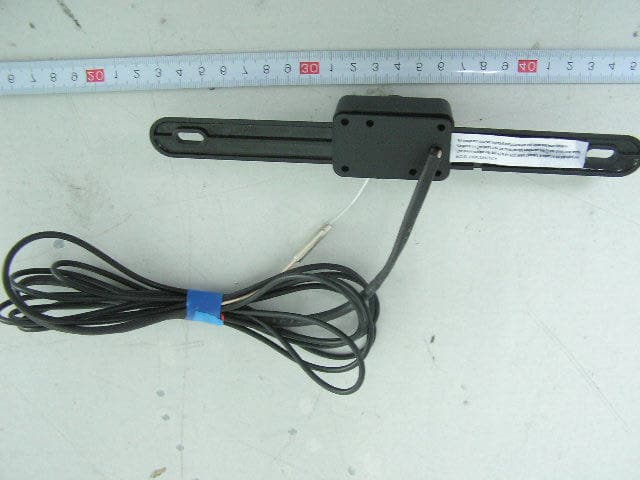
Click to zoom
Application Details
- Equipment Class
- DXX - Part 15 Low Power Communication Device Transmitter
- Date of Grant
- Aug 29, 2006
- Application Purpose
- Original Equipment
- Date of Application
- Aug 29, 2006
- Equipment Note
- Wireless Backup Camera
- Frequency Range
- 2414.00000000 - 2468.00000000
- Company
- Roadmaster (USA) Corp.
- Country
- United States
Documents & Files
Document Text
Text extracted from the exhibit documents filed with the FCC. Open a document above to read the original.
Users Manual
These instructions do not apply to all vehicles. They are meant as only as a general guide due to the number of different makes & models. For vehicle specific questions, contact your vehicle’s manufacturer. Monitor Installation When choosing a location to mount the monitor, make sure the monitor is in an area that will not obstruct your vision while driving. It can be placed on the dashboard, or on the windshield depending on the angle. 1. Temporarily place the moni- tor stand in the location that you have chosen. Make sure the driver’s vision is not ob- structed in any way or any of the vehicle’s 2. Route the monitor’s power cable to the vehicle’s fuse block/box or cigarette lighter socket/12V power outlet de- pending on the cable you are using 3. If you are satisfied with the location of the monitor and the cable route you have chosen, attach the monitor or stand with the supplied Velcro. Monitor Power ConneCtion there are two ways to supply the monitor with power, one uses a 12 Volt cigarette lighter adaptor plugged into the vehicle’s cigarette lighter socket, and the other uses a wiring harness hard wired to the vehicle’s fuse box. 12 Volt Cigarette Lighter Adaptor Using the Monitor’s on/oFF Button 1. Choose a route for the cable from the monitor to the cigarette lighter socket. It can be a direct route with the wire exposed or a route around the dashboard hidden under the vehicle’s inte- rior trim. When using a direct route for the power cable make sure the power cable is secured and will not interfere with the operation of the vehicle. When routing the power cable behind the vehicle’s interior trim be careful not to cut the wire on and sharp edges or pinch and dam- age the cable when re-installing the trim. 2. Plug the end of the power cable into the monitor, 3. Plug the 12 Volt cigarette lighter adaptor into the cigarette lighter socket. 4. Press the ON/OFF button to turn the monitor. Hard wired to Fuse Box Using the Monitor’s on/oFF Switch (Fig. 1) 1. Remove the negative battery cable from the vehicle’s negative battery terminal. 2. Remove the fuses from both of the in-line fuse holders. 3. Connect the Red wire to the 12 Volt +/ACC terminal in the vehicle’s fuse box. See vehicle’s owner’s manual for fuse box diagram. 4. For the ground cable locate an area of metal on the vehicle’s body/firewall that does not have any vehicle components behind it. Sand off any paint to reveal bare metal, this area will be your chassis ground. 5. Drill a hole for the supplied self tapping sheet metal screw. Make sure there are not any ve- hicle components on the other side of where you are drilling the hole. 6. Attach the grounding cable to the chassis ground with the self-tapping sheet metal screw. 7. Plug the power cord into the monitor. 8. Press the ON/OFF button to turn the monitor. Automotive video equipment installations can be difficult at times, even to the most expe- rienced of installation technicians. If you are not confident working with electrical wiring, removing and reinstalling interior panels, carpeting, dashboards or other components of your vehicle, please call our Toll-Free Help Line 1-800-445-1797 and our in-house technical ser- vice team will answer your installation questions. If you have vehicle specific questions, contact the vehicle’s manufacturer, or consider having the VRBCS300 professionally installed. VRBCS300W Back-Up Camera and Monitor Before You Install Parts InstallationInstallation 1 - Back Up Camera 1- TFT LCD Monitor 1 - Monitor Mounting Stand 1 - Monitor Power Cable with 12 Volt Adaptor 1 - Monitor Power Cable with 12V+, 12V-, and Remote Wire 2 - Sets of Velcro 2 - License Plate Screws 2 - License Plate Bolts & Nuts 4 - Wedge Shaped Mounting shims 4 - In-Line Wire Connectors 1 - Sheet Metal Screw 1 - Grommet 6 - Cable ties GIVE US A CALL, WE'LL HELP YOU INSTALL. 1-800-445-1797 PLEASE DO NOT RETURN PRODUCT TO STORE. Visit us on the WEB www.vr-3.com For Information and Technical Assistance, Call Toll-Free in U.S.A. and Canada. Hard wired Using Vehicle’s reverse Light Circuit for on/oFF (Fig. 2) 1. Remove the negative battery cable from the vehicle’s negative battery terminal. 2. Remove the fuses from both of the in-line fuse holders. 3. Connect the Red wire to the 12 Volt +/ACC terminal in the vehicle’s fuse box. See vehicle’s owner’s manual for fuse box diagram. 4. For the ground cable locate an area of metal on the vehicle’s body/firewall that does not have any vehicle components behind it. Sand off any paint to reveal bare metal, this area will be your chassis ground. 5. Drill a hole for the supplied self tapping sheet metal screw. Make sure there are not any ve- hicle components on the other side of where you are drilling the hole. 6. Attach the grounding cable to the chassis ground with the self-tapping sheet metal screw. 7. Next you will need to locate the vehicle’s reverse light circuit and splice the blue wire into it using the supplied in-line wire connectors. For help locating the vehicle’s reverse light circuit contact your vehicle’s manufacturer for vehicle specific wiring diagrams. LED Power Indictor Image Orientation Button Power ON/OFF Button Power Input Jack (on side of monitor) Monitor ControLS Dear Customer, CONGRATULATIONS. The VRBCS300 Vehicle Reverse Gear Video Camera, when used as described, will give you years of dependable service in your car, truck, RV, or mini-van. We have taken numerous measures in quality control to ensure that your product arrives in top condition, and will perform to your satisfaction. In the rare event that your VRBCS300 Ve- hicle Reverse Gear Video Camera contains a damaged or missing item, does not perform as specified, requires warranty service, or you have an installation problem, DO NOT RETURN THIS PRODUCT TO THE STORE. PLEASE CALL OUR TOLL FREE NUMBER FROM THE U.S.A. AND CANADA 1-800-445-1797 and ask to speak with a member of our technical service team, or submit your questions by e-mail to customerservice@vr-…
Text truncated - open the document above for the full version.
Block Diagram
BLOCK DIAGRAM ANTENNA 2414 – 2468 MHz VIDEO 3.3V 5.0V 5.0V DC/DC 5V OUTPUT 9.6-14.4V POWER INPUT 2.4 GHz WIRELESS TRANSMITTER 3.3V LINEAR REGULATOR 2.8V LINEAR REGULATOR ¼ INCH SENSOR M1360 OV0702 VIDEO SIGNAL PROCESSOR BRIGHTNESS CONTROL OSC 17.734475 MHz 2.5MM COLOR LENSE 3.3V
External Photos
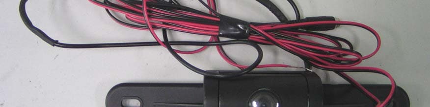
External Photos EUT-Front View EUT-Back View
ID Label/Location Info
ID Label Label FCC ID: UHIVRBCS300WCA
ID Label/Location Info
ID Label/Location Label Location Information Specifications: Text is Black or white in color and is left justified. Labels are printed in indelible ink on permanent adhesive backing or silk-screened onto the EUT or shall be affixed at a conspicuous location on the EUT. Label Location
Internal Photos
Internal Photos EUT-Inside View EUT-PCB View (1) EUT-PCB View (2)
Operational Description
Circuit Description The lens gathers the video information and the information will be changed into video signal in 1/4 inch Sensor MI360, then the signal will be processed by the OV0702 Video Signal Processor. The brightness can be controlled. The video signal will be transmitted by 2.4GHz Wireless Transmitter. The power is regulated by the linear regulator.
Schematics
PDF created with pdfFactory trial version www.pdffactory.com
Test Report
Note: The test report is specially limited to the above company and this particular sample only. It may not be duplicated without prior written consent of Bay Area Compliance Lab Corp. (ShenZhen). This report must not be used by the client to claim product certification, approval, or endorsement by NVLAP, NIST or any agency of the US Government. FCC PART 15.249 EMI MEASUREMENT AND TEST REPORT For Roadmaster(USA) Corp. 41 James Way Eatontown, NJ 07724 USA FCC ID: UHIVRBCS300WCA August 25, 2006 This Report Concerns: Original Report Equipment Type: Wireless Backup Camera Test Engineer: Charmi Peng Report No.: RSZ06081101 Test Date: August 24, 2006 Reviewed By: EMC Manager: Boni Baniqued Prepared By: Bay Area Compliance Lab Corp. (ShenZhen) 6/F, the 3rd Phase of WanLi Industrial Building, ShiHua Road, FuTian Free Trade Zone, ShenZhen, Guangdong 518038, P.R.China Tel: +86-755-33320018 Fax: +86-755-33320008 Roadmaster(USA) Corp. FCC ID: UHIVRBCS300WCA Report # RSZ06081101.doc Page 2 of 18 FCC PART 15.249 Report TABLE OF CONTENTS GENERAL INFORMATION.......................................................................................................................................................2 PRODUCT DESCRIPTION FOR EQUIPMENT UNDER TEST (EUT)...............................................................................................2 OBJECTIVE.......................................................................................................................................................................................2 RELATED SUBMITTAL(S)/GRANT(S)............................................................................................................................................2 TEST METHODOLOGY....................................................................................................................................................................2 TEST FACILITY................................................................................................................................................................................2 EXTERNAL I/O CABLE...................................................................................................................................................................2 SYSTEM TEST CONFIGURATION.........................................................................................................................................2 JUSTIFICATION................................................................................................................................................................................2 EQUIPMENT MODIFICATIONS........................................................................................................................................................2 CONFIGURATION OF TEST SETUP.................................................................................................................................................2 BLOCK DIAGRAM OF TEST SETUP................................................................................................................................................2 SUMMARY OF TEST RESULTS..............................................................................................................................................2 §15.203 - ANTENNA REQUIREMENT....................................................................................................................................2 STANDARD APPLICABLE...............................................................................................................................................................2 ANTENNA CONNECTOR CONSTRUCTION....................................................................................................................................2 §15.205 §15.209(A) §15.249(A) - RADIATED EMISSION...................................................................................................2 MEASUREMENT UNCERTAINTY....................................................................................................................................................2 EUT SETUP.....................................................................................................................................................................................2 EMI TEST RECEIVER SETUP.........................................................................................................................................................2 TEST EQUIPMENT LIST AND DETAILS.........................................................................................................................................2 TEST PROCEDURE...........................................................................................................................................................................2 CORRECTED AMPLITUDE & MARGIN CALCULATION...............................................................................................................2 TEST RESULTS SUMMARY.............................................................................................................................................................2 TEST DATA......................................................................................................................................................................................2 §15.249(D) – OUT OF BAND EMISSION................................................................................................................................2 STANDARD APPLICABLE...............................................................................................................................................................2 TEST PROCEDURE...........................................................................................................................................................................2 TEST EQUIPMENT LIST AND DETAILS................................…
Text truncated - open the document above for the full version.
Test Setup Photos
Test Setup Photos Radiated Emission-Front View (30MHz-1000MHz) Radiated Emission-Rear View (30MHz-1000MHz) Radiated Emission-Front View (Above 1GHz) Radiated Emission-Rear View (Above 1GHz)
Contact Information
Applicant
Ben. Pivinski(manager)
Test Firm
Bay Area Compliance Laboratory Corp. (Shenzhen)John Chan
Technical Specifications
| # | Rule Parts | Frequency Range | Power Output |
|---|---|---|---|
| 1 | 15C | 2.41 GHz - 2.47 GHz | - |
Other Applications from Roadmaster (USA) Corp.
UHIVRBCS335WCA
Sep 30, 2007Wireless Car Rear View Camera and Receiver
Equipment Class
DXX - Part 15 Low Power Communication Device Transmitter
UHIPI-01
Mar 29, 2007In-Car FM Transmitter
Equipment Class
DXX - Part 15 Low Power Communication Device Transmitter
UHIVRFM8
Dec 21, 2006MP3 FM TRANSMITTER
Equipment Class
DXX - Part 15 Low Power Communication Device Transmitter