UHJPOWERTOWERTotal Gym
Engineering Fitness International Corporation dba Total Gym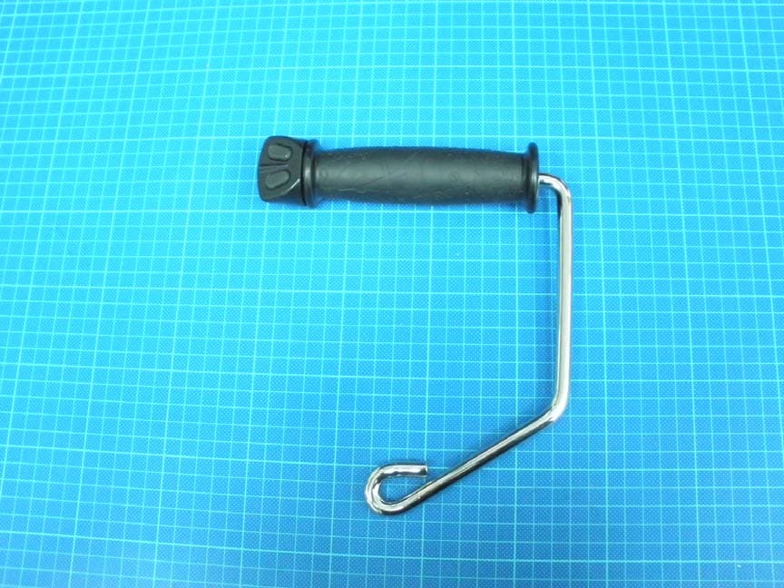
Click to zoom
Application Details
- Equipment Class
- DSC - Part 15 Security/Remote Control Transmitter
- Date of Grant
- Mar 18, 2012
- Application Purpose
- Original Equipment
- Date of Application
- Mar 18, 2012
- Equipment Note
- Total Gym
- Frequency Range
- 433.92000000 - 433.92000000
- Country
- United States
Documents & Files
Document Text
Text extracted from the exhibit documents filed with the FCC. Open a document above to read the original.
Users Manual
TotalGym.com | 800 541 4900 © 2011 Total Gym Global Corp ACCESSORIES | INCLINE BODYWEIGHT TRAINING Wireless Control Handle (Set of 2) / XXXXX REPLACING OR USING ADDITIONAL WIRELESS CONTROL HANDLES If you must replace a lost or damaged handle or if you purchase a second set of Wireless Control Handles for your PowerTower ® , you will need to reprogram the tower to accept the new handle code. The code in each set of Wireless Control Handles is unique and is permanently set at the factory. The PowerTower must be reprogrammed to accept the code of each handle set before it will accept wireless control commands. STEPS TO REPROGRAM YOUR POWERTOWER TO ACCEPT THE NEW HANDLE CODE 1 Power Switch STEP 1. Turn the red power switch to the “Off” position on the back base of the PowerTower unit. 2 STEP 2. Then turn the power switch back to the “On” position. Within 10 seconds, insert a paper clip or similar object into the hole in the top of the tower and gently press into the hole as shown. The LED will light up. 3 Safety KeyLED Rocker Switch STEP 3. Press and hold down either button on the Wireless Control Handle that you are programming. If you are programming two Wireless Control Handles: • Press and hold one button on the first handle. The LED light will flash, then become steady. • Within 3 more seconds, press and hold one button on the other handle. The light will flash again and then become steady. When the LED light turns off, programming is complete and your PowerTower will immediately respond when the handle buttons are pressed. NOTE: The Rocker Switch on the top of the tower will always operate the PowerTower, whether a Wireless Control Handle is programmed or not. FCC RULES The PowerTower Wireless Control Handle is a wireless transmitter that complies with FCC Rules, Part 15. Operation is subject to the following two conditions: 1. this device may not cause harmful interference, and 2. this device must accept any interference received, including interference that may cause undesired operation. RSS RULES This device complies with Industry Canada license-exempt RSS standard(s). Operation is subject to the following two conditions: 1. this device may not cause interference, and 2. this device must accept any interference, including interference that may cause undesired operation of the device. Le présent appareil est conforme aux CNR d’Industrie Canada applicables aux appareils radio exempts de licence. L’exploitation est autorisée aux deux conditions suivantes: 1. l’appareil ne doit pas produire de brouillage, et 2. l’utilisateur de l’appareil doit accepter tout brouillage radioélectrique subi, même si le brouillage est susceptible d’en compromettre le fonctionnement. Lowers incline level Raises incline level
External Photos
External photo of EUT
Internal Photos
Internal photo of EUT Internal photo of EUT Internal photo of EUT RF Module & Antenna
Test Report
FCC ID. :UHJPOWERTOWER Report No.: TS10080061-EME Page 1 of 19 EMC TEST REPORT Report No. : TS10080061-EME Model No. : 5300-01, 5100-01, 5200-01 Issued Date : Jan. 07, 2011 Applicant: ENGINEERING FITNESS INTERNATIONAL CORPORATION DBA TOTAL GYM 7755 ARJONS DRIVE, SAN DIEGO, CA 92126 Test Method/ Standard: FCC Part 15C 15.231 and according to the procedures in ANSI C63.4.2003 Test By: Intertek Testing Services Taiwan Ltd. No. 11, Ko-Tze-Nan Chia-Tung Li, Shiang-Shan District, Hsinchu, Taiwan It may be duplicated completely for legal use with the allowance of the applicant. It shall not be reproduced except in full, without the written approval of Intertek Laboratory. The test result(s) in this report only applies to the tested sample(s). The test report was prepared by: Sign on File Julie Wang / Senior Assistant These measurements were taken by: Sign on File Terry Hsu/ Engineer The test report was reviewed by: Name Jimmy Yang Title Engineer FCC ID. :UHJPOWERTOWER Report No.: TS10080061-EME Page 2 of 19 Table of Contents Summary of Tests ............................................................................................................. 3 1. General information...................................................................................................... 4 1.1 Identification of the EUT........................................................................................ 4 1.2 Additional information about the EUT ................................................................... 4 2. Test specifications.........................................................................................................5 2.1 Test standard ........................................................................................................... 5 2.2 Operation mode ...................................................................................................... 5 2.3 Test equipment........................................................................................................ 6 3. Radiated emission test FCC 15.231 (b) ........................................................................ 7 3.1 Operating environment ........................................................................................... 7 3.2 Test setup & procedure ........................................................................................... 7 3.3 Radiated emission limit .......................................................................................... 9 3.3.1 Fundamental and harmonics emission limits ...................................................... 9 3.3.2 General radiated emission limit ......................................................................... 10 3.4 Calculation of Average Factor ...............................................................................11 3.5 Transmitting Time .................................................................................................11 3.6 Radiated emission test data FCC 15.231 .............................................................. 17 3.6.1 Measurement results: frequencies equal to or less than 1 GHz ......................... 17 3.6.2 Measurement results: frequencies above 1GHz ................................................ 18 4. Measured bandwidth FCC 15.231 (C)........................................................................ 19 FCC ID. :UHJPOWERTOWER Report No.: TS10080061-EME Page 3 of 19 Summary of Tests Test Reference Results Radiated Emission test 15.231(b), 15.209 Pass Measured bandwidth 15.231(c) Pass FCC ID. :UHJPOWERTOWER Report No.: TS10080061-EME Page 4 of 19 1. General information 1.1 Identification of the EUT Manufacturer : TUNG KENG ENTERPRISE CO., LTD Product : Total Gym Model No. : 5300-01 FCC ID. : UHJPOWERTOWER Frequency Range : 433.92 MHz Channel Number : Single channel Frequency of each channel : 433.92 MHz Type of Modulation : ASK Power Supply : DC 12V from battery Power Cord : N/A Sample Received : Aug. 06, 2010 Test Date(s) : Oct. 15, 2010 ~ Dec. 29, 2010 1.2 Additional information about the EUT The EUT is a Total Gym, and was defined as information technology equipment. The customer confirmed the models listed below were identical to model 5300-01 (EUT). Different brands served as marketing strategy. Trade Name Model Number Total Gym PowerTower5300-01 Total Gym Sport 5100-01 Total Gym GTS 5200-01 For more detail features, please refer to User's manual as file name “Installation guide.pdf” FCC ID. :UHJPOWERTOWER Report No.: TS10080061-EME Page 5 of 19 2. Test specifications 2.1 Test standard The EUT was performed according to the requirement in FCC Part 15C 15.231 and according to the procedures in ANSI C63.4.2003 2.2 Operation mode The EUT was supplied with DC 12V from battery and it was running in operating mode. The EUT was transmitted continuously during the test. FCC ID. :UHJPOWERTOWER Report No.: TS10080061-EME Page 6 of 19 2.3 Test equipment Equipment Brand Frequency rangeModel No. Last Cal. Cal. interval EMI Test Receiver Rohde & Schwarz 9kHz~2.75GHz ESCS 30 2010/9/3 1 year Spectrum Analyzer Rohde & Schwarz 9kHz~30GHz FSP 30 2010/8/16 1 year Spectrum Analyzer Rohde & Schwarz 20Hz~40GHz FSEK 30 2010/1/18 1 year Horn Antenna SCHWARZBECK 1GHz~18GHz BBHA9120D 2010/8/31 2 years Bilog Antenna SCHWARZBECK 25MHz~1.7GHzVULB 9168 2009/9/22 2 years Turn Table HDGmbH N/A DS 420S N/A N/A Antenna Tower HDGmbH N/A MA 240 N/A N/A Pre-Amplifier MITER 100MHz~26.5GHz AFS42-00102650 2009/10/27 2 years LISN Rohde & Schwarz 9KHz~30MHz ESH3-Z5 2009/3/13 2 years Power Meter Anritsu N/A 2495A 2010/10/20 1 year Power Senor Anritsu N/A 2411B 2010/10/20 1 year Note: The above equipments are within the valid calibration period. FCC ID. :UHJPOWERTOWER Report No.: TS10080061-EME Page 7 of 19 3. Radiated emission test FCC 15.231 (b) 3.1 Operating environment Temperature: 24 °C Relative Humidity: 55 % Atmospheric Pressure 1008 hPa 3.2 Test setup & procedure The Diagram below shows the test setup, w…
Text truncated - open the document above for the full version.
Test Setup Photos
Photo 1: Radiated Emission Test set-up photo Photo 2: Radiated Emission Test set-up photo
Contact Information
Applicant
Dan McCutcheon(Sr. Mechanical Engineer)
Test Firm
Intertek Testing Services Taiwan Ltd.Alpha Liu
Technical Specifications
| # | Rule Parts | Frequency Range | Power Output |
|---|---|---|---|
| 1 | 15.231 | 433.92 MHz - 433.92 MHz | - |