UHK752TCLCM110CDMA 1X MOBILE TELEPHONE
TCL Communication Equipment (HUIZHOU) Co., Ltd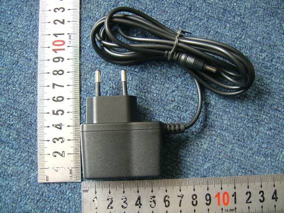
Click to zoom
Application Details
- Equipment Class
- TNE - Licensed Non-Broadcast Transmitter Held to Ear
- Date of Grant
- Sep 11, 2006
- Application Purpose
- Original Equipment
- Date of Application
- Sep 11, 2006
- Equipment Note
- CDMA 1X MOBILE TELEPHONE
- Frequency Range
- 825.25000000 - 847.75000000
- Country
- China
Documents & Files
Document Text
Text extracted from the exhibit documents filed with the FCC. Open a document above to read the original.
Users Manual
Safety and Precautions_______________________________________ 2 Phone Layout______________________________________________ 4 Essential Topics_____________________________________________ 6 Getting started______________________________________________ 7 Basic operations___________________________________________ 10 Using the menu____________________________________________ 12 Menu option list___________________________________________ 13 SMS_____________________________________________________ 15 Recent Calls_______________________________________________ 16 Settings__________________________________________________ 17 Games___________________________________________________ 20 To o l s____________________________________________________ 20 Contact__________________________________________________ 21 Operation instruction of input methods_________________________ 24 Appendix I Common fault diagnosis___________________________ 25 Appendix II Abbreviations and explanations___________________ 25 Appendix III RF Exposure_________________________________ 26 (Note): Teleepoch reserves the right to change or improve the product’s design, specifications, and other descriptions in this manual without prior notice. Teleepoch also reserves the final explanation right for this manual. 第 1 页 Safety and Precautions Switch off the phone in the vicinity of chemical plants, gas stations and other locations containing explosive objects. Keep the phone away from children. Please switch off your phone as instructed where notices are present. Switch off the phone when boarding on plane and don’t switch on the phone during flight. Please strictly conform to your local legal regulations during a drive. When hands free function is available, please use the hands free calling device to ensure safety. Please park the car at roadside for communication unless in emergency. Take special care when using the mobile phone in the vicinity of such devices as pacemakers, hearing aids and electro-medical equipment, which may be interfered by the mobile phone. When the phone is switched on, a minimum distance of 6 inches (15cm) shall be kept between the phone and pacemaker. When using other medical equipments, please consult the vendors of these equipments or doctors for relevant information. No guarantee for the accessories and fitments not produced by the original factory. Never attempt to disassemble the phone by unauthorized persons. Contact the authorized service center in your region in case of any trouble with your mobile phone. Recharge of the phone without battery being installed is prohibited. Charge the phone in well-ventilated environment, and keep it away from inflammable and high explosive articles. To avoid demagnetization, keep the handset away from magnetic substances such as magnetic discs or credit cards. Ensure to keep the handset away from liquid. Take the battery off and contact the authorized service center if the handset gets soaked or erosion can happen. Avoid using the phone in too high or too low temperature environments. Never leave the phone exposed under direct sunlight or in high humidity or dusty environment. Do not use liquids or damp cloth with strong detergents to clean the handset. Avoiding dropping, crashing or excessively squeezing the phone, or it may be subject to damages of different degrees. Description about UIM card involved in this user manual is only effective for the phone withUIM card. The menus and operations correlative to UIM, such as PIN code, will not be exactly the same as the real ones, which shall prevail! For body worn operation this phone has been tested and meets FCC RF exposure guidelines when used with an accessory that contains no metal and that positions the handset a minimum of 1.5 cm from the body. Use of other accessories may not ensure compliance with FCC RF exposure guidelines. 第 2 页 〈Note〉: This user manual is the operating instructions based on the simple English operating mode, and it is Somewhat different other language mode. 〈Wa r n i n g〉: The original factory will not take any responsibility in the case of noncompliance with the above advices or improper use of the phone. 〈Attention〉: Please send used li-ion batteries to specified locations or return them to our company. Do not dispose of the batteries into dustbins. 第 3 页 Phone Layout This handset has totally 20 keys on the keypad. It has 1.4 inches STN(or CSTN with 4K colors for colorful display product)screen. Also it has a recharge interface. Speaker Display Screen Receiver Lanyard Hole Ear-Jack DC-JACK Alphanumeric Keypads Phone Bottom Side、Back Side and Front Side Schematic Diagram Note: The phone’s schematic diagram will not be exactly the same as the real one, which shall prevail! 第 4 页 Specifications list Phone Type Specification CD10/CD40 Dimensions 98×44×19mm Weight Approx. 66g Screen display resolution 102×80 pixels Accessories Traveling charger, standard battery Card type* UIM card Applicable system CDMA 2000 1X 1900MHz Contact capacity*Depend on type in UIM card and 100 sets in mobile phone SMS capacity*Depend on type in UIM card and 50 pieces for inbox and 50 pieces for outbox in mobile phone Preset short message 10 preset short messages Call records 20 each for missed, answered and dialed calls Receiving call vibration Support Preset ringing tone type 12 ringing tones Call time Support Speed Dial Support Date and time display Support Alarm/Calculator Support Receiving/Sending short message Support Games Support Caller number display* Support Divert Calls* Support Call Restrict* Support Call Waiting* Support Note: Functions marked with “*” require network or UIM card support. 第 5 页 Essential Topics Communication control keys The key is used for making a call (after a number has been entered); or for viewing recently dialed phone numbers. Maximum 10 numbers can be displayed. The key is used for ending a call (during dialing and communication state), or f…
Text truncated - open the document above for the full version.
External Photos
External Photos 1. Front View of EUT 2. Back View of EUT 3. back view with battery 4. Side View of EUT 5. AC adapter
ID Label/Location Info
Label Label Location
Internal Photos
Internal Photos
RF Exposure Info
No.SAR06-038 Page 3 of 50 Contents 1. GENERAL CONDITIONS 2. ADMINISTRATIVE DATA 2.1. Identification of the Responsible Testing Laboratory 2.2. Identification of the Responsible Testing Location(s) 2.3. Organization Item 2.4. Identification of Applicant 2.5. Identification of Manufacture 3. EQUIPMENT UNDER TEST (EUT) 3.1. Identification of the Equipment under Test 3.2. Identification of all used Test Sample of the Equipment under Test 4. OPERATIONAL CONDITIONS DURING TEST 4.1. Schematic Test Configuration 4.2. SAR Measurement System 5. CHARACTERISTICS OF THE TEST 5.1. Applicable Limit Regulations 5.2. Applicable Measurement Standards 6. LABORATORY ENVIRONMENT 7. TEST RESULTS 7.1. Dielectric Performance 7.2. Summary of Measurement Results 7.3. Conclusion 8. MEASUREMENT UNCERTAINTY 9. MAIN TEST INSTRUMENTS This Test Report consists of the following Annexes: Annex A: Accreditation Certificate Annex B: Test Layout Annex C: Sample Photographs Annex D: Graph Test Results Annex E: System Performance Check Data No.SAR06-038 Page 4 of 50 1ˊGENERAL CONDITIONS 1.1 This report only refers to the item that has undergone the test. 1.2 This report standalone dose not constitute or imply by its own an approval of the product by the certification Bodies or competent Authorities. 1.3 This document is only valid if complete; no partial reproduction can be made without written approval of Shenzhen Electronic Product Quality Testing Center. 1.4 This report cannot be used partially or in full for publicity and/or promotional purposes without previous written approval of Shenzhen Electronic Product Quality Testing Center and the Accreditation Bodies, if it applies. No. SAR06-038 Page 5 of 50 2. Administrative Date 2.1. Identification of the Responsible Testing Laboratory Company Name: ShenZhen Electronic Product Quality Testing Center Department: Testing Department Address: Electronic Testing Building, ShaHe Road, NanShan District, ShenZhen, P. R. China Telephone: +86-755-26628676 Fax: +86-755-26627238 Responsible Test Lab Managers: Mr. Wu Li’an 2.2. Identification of the Responsible Testing Location(s) Company Name: ShenZhen Electronic Product Quality Testing Center Address: Electronic Testing Building, ShaHe Road, NanShan District, ShenZhen, P. R. China 2.3. Organization Item S.E.T Report No.: SAR06-038 S.E.T Project Leader: Mr. Li Sixiong S.E.T Responsible for accreditation scope: Mr. Wu Li’an Start of Testing: 2006-8-20 End of Testing: 2006-8-21 2.4. Identification of Applicant Company Name: TCL COMMUNICATION EQUIPMENT˄HUIZHOU˅CO.,LTD Address: TCL Mansion,10 DaLing Rd.,LongFeng,HuiZhou,GuangDong,PRC Contact person: yinong guo Telephone: +86-752-2288721 Fax: +86-752-2261868 2.5. Identification of Manufacture Company Name: TCL COMMUNICATION EQUIPMENT˄HUIZHOU˅CO.,LTD Address: TCL Mansion,10 DaLing Rd.,LongFeng,HuiZhou,GuangDong,PRC Contact person: yinong guo Telephone: +86-752-2288721 Fax: +86-752-2261868 Notes: This data is based on the information by the applicant. No. SAR06-038 Page 6 of 50 3. Equipment Under Test (EUT) 3.1. Identification of the Equipment under Test Brand Name: TCL Type Name: TCL-CM110 Marking Name: TCL-CM110 Test frequency CDMA 800MHz Development Stage Identical Prototype Accessories Charger Battery type TB-04B Battery specification800mAh 3.7V Antenna type Build inside Operation mode Call established Modulation mode CDMA 1X General description: Max. Power(ERP) 0.270w(24.30dBm) NOTE: 1. The EUT consists of Hand Telephone Set and normal options: Lithium Battery , as listed above. 2. Please refer to Appendix C for the photographs of the EUT. For a more detailed features description about the EUT, please refer to User’s Manual. 3.2. Identification of all used Test Sample of the Equipment under Test EUT Code ESN Hardware Version Software Version MIN N.A.025B1995 C110V1.1 C110V1.4 460030980331979 No. SAR06-038 Page 7 of 50 4 OPERATIONAL CONDITIONS DURING TEST 4.1 Schematic Test Configuration During SAR test, EUT is in Traffic Mode (Channel Allocated) at Normal Voltage Condition. A communication link is set up with a System Simulator (SS) by air link, and a call is established. The TCH is allocated to 9, 384 and 758 respectively in the case of CDMA 800 MHz. The EUT is commanded to operate at maximum transmitting power. The EUT shall use its internal transmitter. The antenna(s), battery and accessories shall be those specified by the manufacturer. The EUT battery must be fully charged and checked periodically during the test to ascertain uniform power output. If a wireless link is used, the antenna connected to the output of the base station simulator shall be placed at least 50 cm away from the handset. The signal transmitted by the simulator to the antenna feeding point shall be lower than the output power level of the handset by at least 35 dB. 4.2 SAR Measurement System The SAR measurement system being used is the IndexSAR SARA2 system, which consists of a Figure1. SAR Lab Test Measurement Set-up Mitsubishi RV-E2 6-axis robot arm and controller, IndexSAR probe and amplifier and SAM phantom No. SAR06-038 Page 8 of 50 Head Shape. The system is controlled remotely from a PC, which contains the software to control the robot and data acquisition equipment. The software also displays the data obtained from test scans. In operation, the system first does an area (2D) scan at a fixed depth within the liquid from the inside wall of the phantom. When the maximum SAR point has been found, the system will then carry out a 3D scan centred at that point to determine volume averaged SAR level. 4.2.1 Robot system specification The robot is used to articulate the probe to programmed positions inside the phantom head to obtain the SAR readings from the DUT. 4.2.2 Probe and amplifier specification IXP-050 Indexsar isotropic immersible SAR probe The probes are constructed using three orthogonal dipole sensors arranged on an interlocking, triangular prism core. The probes have built-in shielding against static ch…
Text truncated - open the document above for the full version.
Test Report
Report No. FCC06-8052 Page 2 of 48 Table of Contents 1 Test Report Certification ...............................................................................................................5 2 General Information ......................................................................................................................6 2.1 Description of EUT ...............................................................................................................6 2.2 Objective ...............................................................................................................................7 2.3 Test Standards and Results ....................................................................................................7 2.4 List of Equipments Used .......................................................................................................8 2.5 Test Facility ...........................................................................................................................8 2.6 Environmental conditions .....................................................................................................8 3 Conducted Emission Measurement...............................................................................................9 3.1 Limits of Conducted Emission..............................................................................................9 3.2 Test Procedure .......................................................................................................................9 3.3 Test Setup ............................................................................................................................10 3.4 EUT Setup and Operating Conditions.................................................................................10 3.5 Test Results .........................................................................................................................10 4 Radiated Emission Test ...............................................................................................................12 4.1 Limits of Radiated Emission ...............................................................................................12 4.2 Test Procedure .....................................................................................................................12 4.3 Test Setup ............................................................................................................................13 4.4 EUT Setup and Operating Conditions.................................................................................13 4.5 Test Results .........................................................................................................................13 5 Frequencies .................................................................................................................................15 5.1 Frequency Blocks Available for Cellular Service ...............................................................15 5.2 Test Procedure .....................................................................................................................15 5.3 Test Setup ............................................................................................................................15 5.4 EUT Setup and Operating Conditions.................................................................................15 5.5 Test Results .........................................................................................................................16 6 Conducted RF Output Power Test...............................................................................................17 6.1 RF Power Output Test Requirement ...................................................................................17 Report No. FCC06-8052 Page 3 of 48 6.2 Test Procedure .....................................................................................................................17 6.3 Test Setup ............................................................................................................................17 6.4 EUT Setup and Operating Conditions.................................................................................17 6.5 Test Results .........................................................................................................................18 7 Occupied Bandwidth Test ...........................................................................................................20 7.1 Definition ............................................................................................................................20 7.2 Test Procedure .....................................................................................................................20 7.3 Test Setup ............................................................................................................................20 7.4 EUT Setup and Operating Conditions.................................................................................20 7.5 Test Results .........................................................................................................................21 8 Conducted Spurious Emission Test.............................................................................................23 8.1 Limits of Conducted Spurious Emission.............................................................................23 8.2 Test Procedure .....................................................................................................................23 8.3 Test Setup ............................................................................................................................23 8.4 EUT Setup and Operating Conditions.................................................................................23 8.5 Test Results ................................................................................................…
Text truncated - open the document above for the full version.
Test Setup Photos
Test Setup Photos 1. CE 2. CSE 3. RE 4. RE-Loop 5. RSE
Contact Information
Applicant
Yinong Guo(Directot)
Test Firm
ShenZhen Electronic Product Quality Testing CenterXingsun Lin
Technical Specifications
| # | Rule Parts | Frequency Range | Power Output | Emission | Tolerance |
|---|---|---|---|---|---|
| 1 | 22 | 825.25 MHz - 847.75 MHz | 270.00 mW | 1M25F9W | 300.0000000000 Hz |