UHXGA6040-RXWireless Backup Camera
Supa Technology Co., Ltd.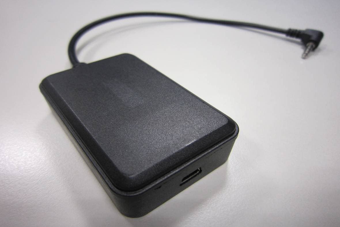
Click to zoom
Application Details
- Equipment Class
- DXX - Part 15 Low Power Communication Device Transmitter
- Date of Grant
- Jun 20, 2011
- Application Purpose
- Original Equipment
- Date of Application
- Jun 20, 2011
- Equipment Note
- Wireless Backup Camera
- Frequency Range
- 2404.12500000 - 2478.37500000
- Company
- Supa Technology Co., Ltd.
- Country
- Taiwan
Documents & Files
Document Text
Text extracted from the exhibit documents filed with the FCC. Open a document above to read the original.
Users Manual
GA 6040 wireless backup camera Introduction: Wireless Reverse Camera GA6040 is design for vehicle owners which wish to self install the reverse camera to their vehicle. 3 major parts are required for installation: Reverse Camera: Which installed outside at the back of the vehicle. Transceiver: Which connects to the reverse light’s power cable and Reverse Camera, it is responsible to wirelessly transfer the camera image to the receiving end. Receiver: Connect to the monitor, which display images from the reverse cam. Video Streaming is transfer in 2.4GHz ISM band, using wireless multimedia processor to overcomes different interferences, like microwave‐oven, and work coexistence with other 2.4GHz wireless devices, like cordless phone, WiFi, bluetooth, wireless keyboard and mouse. The robust anti‐interference capability is controlled by wireless multimedia processor to perform adaptive frequency hopping spreading spectrum protocol. Power input for GA6040 is 12~24V for the transceiver, which is suitable for passenger vehicle include, Sedan, Hatchback, Couple, 4 wheel drive, MVP and SUV. Power converter may require if you wish to install on the larger commercial vehicle. Please check the vehicle battery voltage before installation. Package Content: Packages includes: 1x Camera Module 1x Transceiver for connection with camera module and reverse light’s power cable 1 x Receiver for connection to screen and power. 4x power cable connector Camera Module Specifications Component and Optical Specification Spec. Horizontal FOV Approximately 120° Vertical FOV Approximately 100° Diagonal FOV Approximately 140° F No. 2.0±5% CMOS Sensor Size 1/4” Array Size 640x480 Optical distortion 1.0% Lens Size 1/4” Lens Type 4G UV resistance Yes Anti fog coating Yes/with Self clean ID design Compliance IPX6; IPX7 Storage Temperature +75°C ~ -20°C Operation Humidity 90% RH Power Supply 9~12 V; From Transceiver Cable length 1800 mm Dimension Approximately 30.2mm x 31.6mm x 30.5 mm Step by Step installation Step 1: Connect the receiver to the monitor via 3.5mm AV out connector. Connect the receiver with 5V 0.5~1 amp mini USB car charger. Step 2: Place the transceiver near by the reverse light. Connect the power cable of the transceiver to the power cable of the reverse light. Reconnect the reverse light power cable by using the T shape connector. Connect the power cable of the Transceiver to the T‐Shape connector. Step 3: Temporary fixed the reverse camera to the desire/appropriate location at the back of the car. Whether it is on the recess on the trunk, license plate lights, license plate or on desire position on the bonnet. Connect the camera module to the transceiver. Start the car engine and shift the gear to reverse while pressing the break. Images from reverse cam will automatically displayed on the screen. Repeat the action several times and adjust the camera angle to the best view position if necessary. Camera ID Connected camera’s Video Out and Power in to transceiver. Up and down adjustment: By bending the metallic fixed plate or apply different thickness layer of double sided tape. Left and right adjustment: By apply different layers of double sided tape on the left and right side of the fixed metal plate. Step 4: Cabling thru: to avoid camera cable distract appearance of the vehicle, it is recommended to hide the camera cable in the following location: Remove the license plate light cover and insert the camera cable in. Move the camera cable along the cable holder. Connect the camera cable to the receiver. Example of the complete installation. Note: If reverse light of your vehicle is located at the trunk lid you may fixed the transceiver on the rare bonnet to minimized the complexity of wiring around the vehicle. Warning: Federal Communications Commission (FCC) Statement 15.21 You are cautioned that changes or modifications not expressly approved by the part responsible for compliance could void the user’s authority to operate the equipment. 15.105(b) This equipment has been tested and found to comply with the limits for a Class B digital device, pursuant to part 15 of the FCC rules. These limits are designed to provide reasonable protection against harmful interference in a residential installation. This equipment generates uses and can radiate radio frequency energy and, if not installed and used in accordance with the instructions, may cause harmful interference to radio communications. However, there is no guarantee that interference will not occur in a particular installation. If this equipment does cause harmful interference to radio or television reception, which can be determined by turning the equipment off and on, the user is encouraged to try to correct the interference by one or more of the following measures: ‐Reorient or relocate the receiving antenna. ‐Increase the separation between the equipment and receiver. ‐Connect the equipment into an outlet on a circuit different from that to which the receiver is connected. ‐Consult the dealer or an experienced radio/TV technician for help. This device complies with part 15 of the FCC Rules. Operation is subject to the following two conditions: 1) this device may not cause interference and 2) this device must accept any interference, including interference that may cause undesired operation of the device.
External Photos
FCC ID: UHXGA6040-RX International Standards Laboratory APPENDIX 2 EXTERNAL PHOTOGRAPHS OF EUT FCC ID: UHXGA6040-RX International Standards Laboratory Front View of EUT Back View of EUT FCC ID: UHXGA6040-RX International Standards Laboratory Site View of EUT
ID Label/Location Info
FCC ID LABEL FORMAT AND LOCATION Applicant: Supa Technology Co., Ltd FCC ID: UHXGA6040-RX
Internal Photos
FCC ID: UHXGA6040-RX International Standards Laboratory APPENDIX 3 INTERNAL PHOTOGRAPHS OF EUT FCC ID: UHXGA6040-RX International Standards Laboratory Open View of EUT Internal of EUT – 1 RF Ant. FCC ID: UHXGA6040-RX International Standards Laboratory Internal of EUT – 2 Internal of EUT – 3 FCC ID: UHXGA6040-RX International Standards Laboratory Internal of EUT – 5 Internal of EUT – 6 FCC ID: UHXGA6040-RX International Standards Laboratory Internal of EUT – 7
Test Report
Page: 1 of 29 TEST REPORT of FCC Part 15 Subpart C New Application; Class I PC; Class II PC Product : GA6040 Wireless Backup Camera Brand: SUPA / GONAV / MITAC / NAVAIR Model: GA6040 Model Difference: N/A FCC ID: UHXGA6040-RX FCC Rule Part: §15.249 Applicant: Supa Technology Co., Ltd Address: 7F, no 19-5, Sanchong Rd, Nangang District Taipei, 115, Taiwan, R.O.C Test Performed by: International Standards Laboratory <Lung-Tan LAB> *Site Registration No. BSMI: SL2-IN-E-0013; MRA TW1036; TAF: 0997; IC: IC4067B-3; *Address: No. 120, Lane 180, San Ho Tsuen, Hsin Ho Rd. Lung-Tan Hsiang, Tao Yuan County 325, Taiwan *Tel : 886-3-407-1718; Fax: 886-3-407-1738 Report No.: ISL-11LR041FC Issue Date : 2011/06/10 Test results given in this report apply only to the specific sample(s) tested and are traceable to national or international standard through calibration of the equipment and evaluating measurement uncertainty herein. This report MUST not be used to claim product endorsement by TAF, NVLAP or any agency of the Government. This test report shall not be reproduced except in full, without the written approval of International Standards Laboratory. -2 of 29- FCC ID: UHXGA6040-RX International Standards Laboratory Report Number: ISL-11LR041FC VERIFICATION OF COMPLIANCE Applicant: Supa Technology Co., Ltd Product Description: GA6040 Wireless Backup Camera Brand Name: SUPA / GONAV / MITAC / NAVAIR FCC ID: UHXGA6040-RX FCC Rule Part: §15.249 Model No.: GA6040 Model Difference: N/A Date of test: 2011/05/25 ~ 2011/05/28 Date of EUT Received: 2011/05/25 We hereby certify that: All the tests in this report have been performed and recorded in accordance with the standards described above and performed by an independent electromagnetic compatibility consultant, International Standards Laboratory. The test results contained in this report accurately represent the measurements of the characteristics and the energy generated by sample equipment under test at the time of the test. The sample equipment tested as described in this report is in compliance with the limits of above standards. Test By: Date: 2011/06/10 Dion Chang / Engineer Prepared By: Date: 2011/06/10 Eva Kao / Asst. Supervisor Approved By: Date: 2011/06/10 Jim Chu / Director -3 of 29- FCC ID: UHXGA6040-RX International Standards Laboratory Report Number: ISL-11LR041FC Version Version No. Date Description 00 2011/06/10 Initial creation of document -4 of 29- FCC ID: UHXGA6040-RX International Standards Laboratory Report Number: ISL-11LR041FC Table of Contents 1 GENERAL INFORMATION ................................................................................. 5 1.1 PRODUCT DESCRIPTION......................................................................................................... 5 1.2 RELATED SUBMITTAL(S) / GRANT (S) .................................................................................... 5 1.3 TEST METHODOLOGY............................................................................................................ 5 1.4 TEST FACILITY....................................................................................................................... 5 1.5 SPECIAL ACCESSORIES........................................................................................................... 5 1.6 EQUIPMENT MODIFICATIONS................................................................................................. 5 2 SYSTEM TEST CONFIGURATION .................................................................... 6 2.1 EUT CONFIGURATION............................................................................................................ 6 2.2 EUT EXERCISE....................................................................................................................... 6 2.3 TEST PROCEDURE................................................................................................................... 6 2.4 MEASUREMENT EQUIPMENT USED: ....................................................................................... 7 2.5 LIMITATION............................................................................................................................ 8 2.6 CONFIGURATION OF TESTED SYSTEM.................................................................................. 10 3 SUMMARY OF TEST RESULTS........................................................................ 11 4 DESCRIPTION OF TEST MODES..................................................................... 11 5 CONDUCTED EMISSIONS TEST...................................................................... 12 5.1 MEASUREMENT PROCEDURE: .............................................................................................. 12 5.2 TEST SET-UP (BLOCK DIAGRAM OF CONFIGURATION) ...................................................... 12 5.3 MEASUREMENT EQUIPMENT USED: ..................................................................................... 12 5.4 MEASUREMENT RESULT: ..................................................................................................... 12 6 RADIATED EMISSION TEST ............................................................................ 17 6.1 MEASUREMENT PROCEDURE............................................................................................... 17 6.2 TEST SET-UP (BLOCK DIAGRAM OF CONFIGURATION) ...................................................... 17 6.3 MEASUREMENT EQUIPMENT USED: ..................................................................................... 18 6.4 FIELD STRENGTH CALCULATION......................................................................................... 18 6.5 MEASUREMENT RESULT...................................................................................................... 19 7 20 DB BAND WIDTH MEASUREMENT ........................................................... 26 7.1 MEASUREMENT PROCEDURE.....................................................................…
Text truncated - open the document above for the full version.
Test Setup Photos
FCC ID: UHXGA6040-RX International Standards Laboratory APPENDIX 1 PHOTOGRAPHS OF SETUP FCC ID: UHXGA6040-RX International Standards Laboratory Radiated Emission Setup Photos FCC ID: UHXGA6040-RX International Standards Laboratory Conducted Emission Setup Photos
Contact Information
Applicant
Jake Lin
Technical Contact
Test Firm
International Standards Laboratory Corp.Benson Chen
Technical Specifications
| # | Rule Parts | Frequency Range | Power Output |
|---|---|---|---|
| 1 | 15C | 2.40 GHz - 2.48 GHz | - |
Other Applications from Supa Technology Co., Ltd.
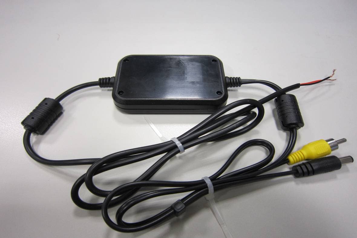
UHXGA6040-TX
Jun 20, 2011Wireless Backup Camera
Equipment Class
DXX - Part 15 Low Power Communication Device Transmitter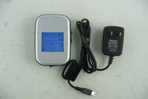
UHXH-2000
Mar 06, 2007Bluetooth GPS Receiver
Equipment Class
DSS - Part 15 Spread Spectrum Transmitter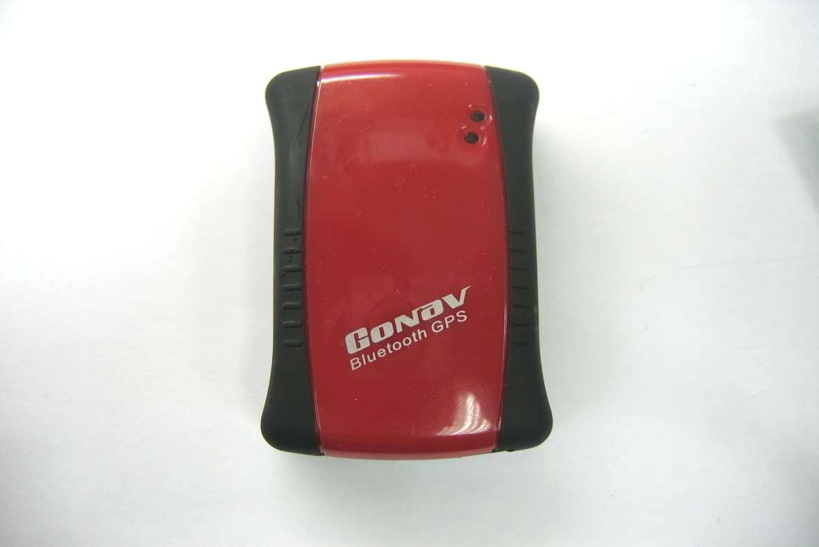
UHXBT-1000
Sep 19, 2006Bluetooth GPS Receiver
Equipment Class
DSS - Part 15 Spread Spectrum Transmitter