UJX-DCM127-001Streetlight Dimming Control Module
Strategic Services Group, Inc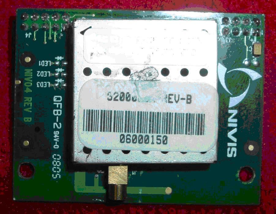
Click to zoom
Application Details
- Equipment Class
- DTS - Digital Transmission System
- Date of Grant
- Jul 05, 2010
- Application Purpose
- Original Equipment
- Date of Application
- Jul 05, 2010
- Equipment Note
- Streetlight Dimming Control Module
- Frequency Range
- 2405.50000000 - 2475.50000000
- Country
- United States
Documents & Files
Document Text
Text extracted from the exhibit documents filed with the FCC. Open a document above to read the original.
Users Manual
ROAM/SSG – A Division of Acuity Brands Dimming Control Module User’s Manual THIS DOCUMENT IS ROAM/SSG PROPRIETARY Page 1/14 DCM User’s Manual DCM127-NX1 Dimming Control Module (contains UJX-DCM127-001) ROAM/SSG – A Division of Acuity Brands Dimming Control Module User’s Manual THIS DOCUMENT IS ROAM/SSG PROPRIETARY Page 2/14 REVISION HISTORY Date VersionDescription Author 6/28/2010 1.0 Initial Draft Ryan Wagner ROAM/SSG – A Division of Acuity Brands Dimming Control Module User’s Manual THIS DOCUMENT IS ROAM/SSG PROPRIETARY Page 3/14 DCM127-NX1 dimming control module intended for streetlight dimming applications contains proposed FCC ID UJX-DCM127-001 2.4GHz radio modem, also known as Nivis 2.4GHz Mod 2 (part number RF-P9-06-01-01). DCM127-NX1 Specifications: Supply voltage: 120-277VAC 60Hz Power: 1.5-2.0W Output: 0-10V analog signal settable in 256 increments Operating Temperature Range: -40C to +85C Storage Temperature Range: -40C to +100C Application: Streetlight fixtures 25W-1000W using electronic ballast or driver with 0-10V analog diming control input. Dim command from ROAM portal software is interpreted by DCM127- NX1, which engages a variable analog output signal commanding the fixture driver to vary the overall fixture illumination. Installation: 1. Ensure the fixture is not powered. Merely removing the photocontrol or shorting cap is not sufficient – power must be disconnected ROAM/SSG – A Division of Acuity Brands Dimming Control Module User’s Manual THIS DOCUMENT IS ROAM/SSG PROPRIETARY Page 4/14 from the field wiring terminal block. Verify power is removed using a working VOM. 2. Open the fixture electronics enclosure (process varies depending on the fixture make/model). 3. Install the DCM (with or without custom mounting bracket specific to the fixture – dependant on make/model of fixture). The DCM enclosure has mounting tabs that will accommodate up to a #10 screw. A #8 or #10 screw are recommended with a lock or star washer. Ideally, the mounting bosses or bracket will position the DCM directly underneath the NEMA receptacle when the fixture is closed. 4. Locate the 120-277VAC fixture supply wiring and terminal block. If the fixture wiring adheres to NEC standards, this will be a black/white conductor pair. Verify the intended power source is not switched by the photocontrol (not through the red conductor coming from the NEMA receptacle) rather is supplied directly from the black/white conductor pair coming directly from the field wiring terminal block. ROAM/SSG – A Division of Acuity Brands Dimming Control Module User’s Manual THIS DOCUMENT IS ROAM/SSG PROPRIETARY Page 5/14 This will be the location that supplies power to the DCM. 5. Determine the type of termination needed. 1. If the field wiring terminal block is the only option, then typically ¼” QC male spade terminals are used (different fixtures may use different size terminals though). In this case, the matching female QC spade terminals must be installed (crimped) to the DCM power leads. 2. Some fixtures may provide an auxiliary power connector. In this case, the matching type mating connector must be installed to the DCM power input (black and white) leads. 3. Some fixtures may include tool-less quick connect terminations. These will require no additional hardware installation to support DCM provided there are open conductor slots available on terminations that include the wiring described in #4. 6. Terminate the black and white power supply wires on the DCM to the AC power source as appropriate for the type described above. ROAM/SSG – A Division of Acuity Brands Dimming Control Module User’s Manual THIS DOCUMENT IS ROAM/SSG PROPRIETARY Page 6/14 7. Locate the dimming driver/ballast 0-10V input wires (violet and grey) and determine the type of termination needed. If multiple drivers are present within the fixture, there will be multiple pairs of driver dimming inputs to terminate to the DCM output wires. The DCM can control up to 4 drivers in parallel. 1. Typically, tool-less QC connectors are used, these will require no additional hardware to terminate the DCM control wires. 2. Butt splices are also viable since the DCM output wires will be connecting only to the driver input wires. If used, ensure that the butt splice terminals are appropriately sized for #18AWG wire and have proper insulation for the specific fixture application. 8. Terminate the DCM 0-10V output (grey/violet) wires to the ballast/driver 0-10V input wires (grey//violet) assuring that like colors match. 9. Carefully route and wire tie/anchor all DCM wiring as needed to ensure that it cannot be pinch or stripped when the electronics enclosure or fixture access panel is closed. ROAM/SSG – A Division of Acuity Brands Dimming Control Module User’s Manual THIS DOCUMENT IS ROAM/SSG PROPRIETARY Page 7/14 Also try to avoid situations where the DCM wiring may come into direct contact with extreme heat sources such as LED heat sink assembly, etc. Carefully close the fixture while ensuring that no new wiring is pinched, stripped or disconnected while doing so. 10. DCM installation is complete. Different methods may be employed to electrically test the fixture or proof the wiring at this point. Due to differences in manufacturing processes, the remaining steps are included only as an example of possible fixture tests. 11. An AC power source can again be installed to the fixture at the field wiring terminal blocks if desired for fixture testing. Preferably, this is a switched source and it can be turned off during installation of the wiring to be made safe. 12. Install a shorting cap in the NEMA receptacle and apply power to the fixture. 13. When initially powered, the DCM will start at 50% dim command level (5V present on 0-10V output) and will stay that way for 4 seconds. After the 4 second period has elapsed, it will command the driver/ballast to ROAM/SSG – A Division of Acuity Brands Dimming Control Module User’s Manual THIS DOCUMENT IS ROAM/SSG PROPRIET…
Text truncated - open the document above for the full version.
Cover Letter(s)
Confidentiality Request June 2, 2010 American TCB 6731 Whittier Ave. McLean, VA 22101 RE : FCC ID: UJX-DCM127-001 Dear ATCB : With regards to the exhibits submitted in support of the application for FCC ID: UJX-DCM127-001, please classify the following as confidential under the provision of 47 CFR 0.459: • Schematics • Block diagram • Theory of Operation These exhibits contain technical information that Strategic Services Group, Inc. deems to be sensitive and proprietary. Therefore this information cannot be published. If this information were to be made public it could be used to the disadvantage of the applicant in the marketplace. Sincerely, Sandi McEnery US Tech (Authorized Agent for Strategic Services Group, Inc.) 3505 Francis Circle Alpharetta, GA 30004 PH: 770-740-0717 Fax: 770-740-1508 www.ustech-lab.com
Cover Letter(s)
June 1, 2010 ATCB Applications Examiner RE: Limited Modular Approval for Strategic Services Group, FCC ID: UJX-DCM127-001 Dear Application Examiner: Regarding Part 15 Unlicensed Modular Transmitter Approval, the following requirements called out in FCC Public Notice DA 00-1407 are observed: 1) The modular transmitter must have its own RF shielding. This is intended to ensure that the module does not have to rely upon the shielding provided by the device into which it is installed in order for all modular transmitter emissions to comply with Part 15 limits. It is also intended to prevent coupling between the RF circuitry of the module and any wires or circuits in the device into which the module is installed. Such coupling may result in non-compliant operation. The ROAM DCM model DCM127-NM1 is a completely self contained radio which has its own RF shielding on the RF section. No other RF shielding is required or implemented. 2) The modular transmitter must have buffered modulation/data inputs (if such inputs are provided) to ensure that the module will comply with Part 15 requirements under conditions of excessive data rates or overmodulation. The ROAM DCM model DCM127-NM1 is a completely self contained radio which modulates its own RF transmitter. It controls the data flow to the transmitter section compliant with Part 15 requirements. 3) The modular transmitter must have its own power supply regulation. This is intended to ensure that the module will comply with Part 15 requirements regardless of the design of the power supplying circuitry in the device into which the module is installed. The module itself has no self-contained power regulator, thus the “Limited” scope of this request. However, the ROAM DCM model DCM127-NM1 is a radio module intended for use in products which will ONLY employ 3.3VDC to the module. Therefore, in all its designs, Strategic Services Group, INC will always ensure that the ROAM DCM model DCM127-NM1 radio receives 3.3VDC to the power input port of the module in order to comply with the scope of this certification. 4) The modular transmitter must comply with the antenna requirements of Section 15.203 and 15.204(c). The antenna must either be permanently attached or employ a “unique” antenna coupler (at all connections between the module and the antenna, including the cable). Any antenna used with the module must be approved with the module, either at the time of initial authorization or through a Class II permissive change. The “professional installation” provision of Section 15.203 may not be applied to modules. For this application the ROAM DCM model DCM127-NM1 employs a permanently attached antenna only. 5) The modular transmitter must be tested in a stand-alone configuration, i.e., the module must not be inside another device during testing. This is intended to demonstrate that the module is capable of complying with Part 15 emission limits regardless of the device into which it is eventually installed. Unless the transmitter module will be battery powered, it must comply with the AC line conducted requirements found in Section 15.207. AC or DC power lines and data input/output lines connected to the module must not contain ferrites, unless they will be marketed with the module (see Section 15.27(a)). The length of these lines shall be length typical of actual use or, if that length is unknown, at least 10 centimeters to insure that there is no coupling between the case of the module and supporting equipment. Any accessories, peripherals, or support equipment connected to the module during testing shall be unmodified or commercially available (see Section 15.31(i)). The ROAM DCM model DCM127-NM1 was tested as a standalone unit 6) The modular transmitter must be labeled with its own FCC ID number, and, if the FCC ID is not visible when the module is installed inside another device, then the outside of the device into which the module is installed must also display a label referring to the enclosed module. This exterior label can use wording such as the following: “Contains Transmitter Module FCC ID: XYZMODEL1” or “Contains FCC ID: XYZMODEL1.” Any similar wording that expresses the same meaning may be used. The Grantee may either provide such a label, an example of which must be included in the application for equipment authorization, or, must provide adequate instructions along with the module which explain this requirement. In the latter case, a copy of these instructions must be included in the application for equipment authorization. The ROAM DCM model DCM127-NM1 consists of a printed circuit board, which is labeled with the FCC identification number. This PCB can be mounted in a host of devices and each device that this PCB utilizes will have the FCC ID number visible to the consumer. 7) The modular transmitter must comply with any specific rule or operating requirements applicable to the transmitter and the manufacturer must provide adequate instructions along with the module to explain any such requirements. A copy of these instructions must be included in the application for equipment authorization. For example, there are very strict operational and timing requirements that must be met before a transmitter is authorized for operation under Section 15.231. For instance, data transmission is prohibited, except for operation under Section 15.231(e), in which case there are separate field strength level and timing requirements. Compliance with these requirements must be assured. The ROAM DCM model DCM127-NM1 comes equipped with embedded firmware that controls these parameters. 8) The modular transmitter must comply with any applicable RF exposure requirements. For example, FCC Rules in Sections 2.1091, 2.1093 and specific Sections of Part 15, including 15.319(i), 15.407(f), 15.253(f) and 15.255(g), require that Unlicensed PCS, UNII and millimeter wave devices perform routine environmental evaluation for RF Exposure to demonstrate compliance. In addition,…
Text truncated - open the document above for the full version.
External Photos
US Tech Test Report, FCC Part 15 Certification FCC ID: UJX-DCM127-001 Test Report Number: 10-0125 Issue Date: May 28, 2010 Customer: Strategic Services Group, INC Model: ROAM DCM model number: DCM127-NM1 Page 1 of 1 Figure 1. Top of Module, with Shielding
ID Label/Location Info
US Tech Test Report, FCC Part 15 Certification FCC ID: UJX-DCM127-001 Test Report Number: 10-0125 Issue Date: May 28, 2010 Customer: Strategic Services Group, INC Model: ROAM DCM model number: DCM127-NM1 EUT with sample Label FCC ID: UJX-DCM127-001 MODEL: 2.4GHz MOD2 radio for DCM MFG: ROAM/SSG
Internal Photos
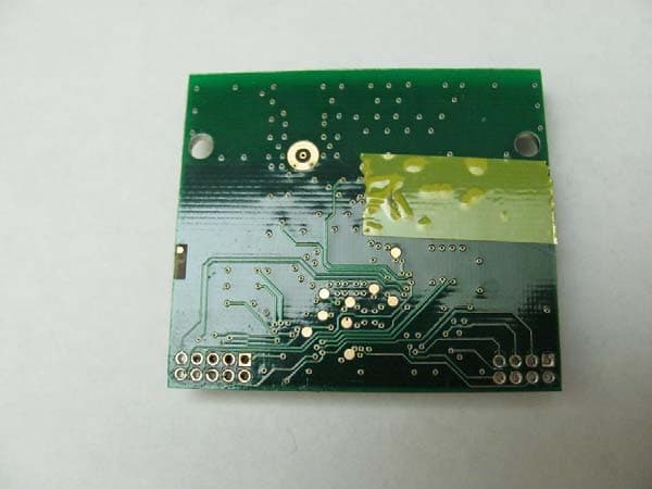
US Tech Test Report, FCC Part 15 Certification FCC ID: UJX-DCM127-001 Test Report Number: 10-0125 Issue Date: May 28, 2010 Customer: Strategic Services Group, INC Model: ROAM DCM model number: DCM127-NM1 Page 1 of 2 Internal Photos Figure 1. Top of Module, Shielding removed US Tech Test Report, FCC Part 15 Certification FCC ID: UJX-DCM127-001 Test Report Number: 10-0125 Issue Date: May 28, 2010 Customer: Strategic Services Group, INC Model: ROAM DCM model number: DCM127-NM1 Page 2 of 2 Figure 2. Bottom of module
RF Exposure Info
US Tech Test Report, FCC Part 15 Certification FCC ID: UJX-DCM127-001 Test Report Number: 10-0125 Issue Date: May 28, 2010 Customer: Strategic Services Group, INC Model: ROAM DCM model number: DCM127-NM1 Page 1 of 1 RF Exposure Maximum Public Exposure to RF (MPE) CFR 15.247 (i) The maximum exposure level to the public from the RF power of the EUT shall not exceed a power density, S, of 1 mW/cm 2 at a distance, d, of 20 cm from the EUT. Therefore, for: Peak Power (Watts) = .08318 (from Table 9, herein) Gain of Transmit Antenna = -1.0 dB i = 0.794, numeric (from Table 4, herein) d = Distance = 20 cm = 0.2 m S = (PG/ 4πd 2 ) = EIRP/4A = 0.08318(0.794)/4*π*0.2*0.2 =0.066045/0.502 = 0.13156 w/m 2 = (W/m 2 ) (1m 2 /W) (0.1 mW/cm 2 ) = 0.013156 mW/cm 2 which is << less than 1 mW/cm 2
Test Report
Page 1 of 47 Application For Title 47 USC, Part 2, Subpart J, Paragraph 2.902, Equipment Authorization of Verification for an Unintentional Radiator per Part 15, Subpart B, Paragraphs 15.107 and 15.109 And Part 2, Subpart J, Paragraph 2.907 Equipment Authorization of Certification for an Intentional Radiator per Part 15, Subpart C, paragraph 15.247 For the Strategic Services Group, Inc. Model: ROAM DCM Model number: DCM127-NX1 FCC ID: UJX-DCM127-001 UST Project: 10-0125 Issue Date: June 14, 2010 Total Pages: 47 3505 Francis Circle Alpharetta, GA 30004 PH: 770-740-0717 Fax: 770-740-1508 www.ustech-lab.com Page 2 of 47 I certify that I am authorized to sign for the Test Agency and that all of the statements in this report and in the Exhibits attached hereto are true and correct to the best of my knowledge and belief: US TECH (Agent Responsible For Test): By: Alan Ghasiani Name: Title: Compliance Engineer – President Date June 14, 2010 This report shall not be reproduced except in full. This report may be copied in part only with the prior written approval of US Tech. The results contained in this report are subject to the adequacy and representative character of the sample provided. 3505 Francis Circle Alpharetta, GA 30004 PH: 770-740-0717 Fax: 770-740-1508 www.ustech-lab.com US Tech Test Report, FCC Part 15 Certification FCC ID: UJX-DCM127-001 Test Report Number: 10-0125 Issue Date: June 14, 2010 Customer: Strategic Services Group, Inc. Model: ROAM DCM model number: DCM127-NM1 Page 3 of 47 MEASUREMENT TECHNICAL REPORT COMPANY NAME: Strategic Services Group, INC. MODEL: DCM127-NX1 FCC ID: UJX-DCM127-001 DATE: June 14, 2010 This report concerns (check one): Original grant X Class II change Equipment type: 2.4 GHz Transmitter Module Deferred grant requested per 47 CFR 0.457(d)(1)(ii)? yes_____ No X If yes, defer until: ______N/A___________ date agrees to notify the Commission by N/A date of the intended date of announcement of the product so that the grant can be issued on that date. Report prepared by: US Tech 3505 Francis Circle Alpharetta, GA 30004 Phone Number: (770) 740-0717 Fax Number: (770) 740-1508 US Tech Test Report, FCC Part 15 Certification FCC ID: UJX-DCM127-001 Test Report Number: 10-0125 Issue Date: June 14, 2010 Customer: Strategic Services Group, Inc. Model: ROAM DCM model number: DCM127-NM1 Page 4 of 47 Table of Contents Paragraph Title Page 1 General Information 7 1.1 Purpose of Report 7 1.2 Characterization of Test Sample 7 1.3 Product Description 7 1.4 Configuration of Tested System 7 1.5 Test Facility 8 1.6 Related Submittal(s) 8 2 Tests and Measurements 10 2.1 Test Equipment 10 2.2 Modifications to Hardware 10 2.3 Number of Measurements (CFR 15.31) 11 2.4 Frequency Range of Radiated Emissions (CFR 15.33) 11 2.4.1 Frequency Range for Intentional Radiator 11 2.4.2 Frequency Range for Unintentional Radiator 11 2.5. Measurement Detector Function and Bandwidth (CFR 15.35) 11 2.5.1 Detector Function and Associated Bandwidth 12 2.5.2 Corresponding Peak and Average Requirements 12 2.5.3 Pulsed Transmitter Averaging 12 2.6 Antenna Requirement (CFR 15.203) 12 2.7 Restricted bands of Operation (CFR 15.205, CFR 15.247(d)) 14 2.8 Transmitter Duty Cycle (CFR 15.35(c)) 14 2.9 Intentional Radiator, Conducted Emissions Power Lines 16 (CFR 15.207) 2.10 Intentional Radiator, Radiated Emissions (CFR 15.209, 17 CFR 15.247(d)) 2.11 Six (6) dB Bandwidth (CFR 15.247(a)(2)) 28 2.12 Maximum Peak Conducted Output Power (CFR 15.247(b)(3)) 32 2.13 Power Spectral Density (CFR 15.247(e)) 36 2.14 Band Edge Measurements (CFR 15.247(d)) 40 2.14.1 Band Edge and Restricted Bands 40 2.14.2 Lower Band Edge 40 2.14.3 Higher Band Edge 40 US Tech Test Report, FCC Part 15 Certification FCC ID: UJX-DCM127-001 Test Report Number: 10-0125 Issue Date: June 14, 2010 Customer: Strategic Services Group, Inc. Model: ROAM DCM model number: DCM127-NM1 Page 5 of 47 Table of Contents (Cont’d) Paragraph Title Page 2.15 Maximum Public Exposure to RF Energy (CFR 15.247(i)) 45 2.16 Unintentional Radiator, Conducted Emissions Power Lines 45 (CFR 15.107) 2.17 Unintentional Radiator, Radiated Emissions (CFR 15.109) 47 List of Figures Figures Title Page 1 Test Configuration 13 2 Transmitter Duty Cycle 15 3 Antenna Conducted Spurious Emissions – CFR 15.247 (d) – 18 Low Channel, Part 1 4 Antenna Conducted Spurious Emissions – CFR 15.247 (d) – 19 Low Channel, Part 2 5 Antenna Conducted Spurious Emissions – CFR 15.247 (d) - 20 Mid Channel, Part 1 6 Antenna Conducted Spurious Emissions – CFR 15.247 (d) - 21 Mid Channel, Part 2 7 Antenna Conducted Spurious Emissions – CFR 15.247 (d) – 22 High Channel, Part 1 8 Antenna Conducted Spurious Emissions – CFR 15.247 (d) – 23 High Channel, Part 2 9 Six (6) dB Bandwidth - 15.247 (a)(2) - Low Channel 29 10 Six (6) dB Bandwidth - 15.247 (a)(2) - Mid Channel 30 11 Six (6) dB Bandwidth - 15.247 (a)(2) - High Channel 31 12 Peak Antenna Conducted Output Power, Low Channel 33 13 Peak Antenna Conducted Output Power, Mid Channel 34 14 Peak Antenna Conducted Output Power, High Channel 35 15 Peak Power Spectral Density - Part 15.247 (e) - Low Channel 37 16 Peak Power Spectral Density - Part 15.247 (e) – Mid Channel 38 17 Peak Power Spectral Density - Part 15.247 (e) - High Channel 39 18 Conducted Band Edge Compliance – Low Channel 42 19 Conducted Band Edge Compliance – High Channel 43 20 Radiated Band Edge Compliance 44 US Tech Test Report, FCC Part 15 Certification FCC ID: UJX-DCM127-001 Test Report Number: 10-0125 Issue Date: June 14, 2010 Customer: Strategic Services Group, Inc. Model: ROAM DCM model number: DCM127-NM1 Page 6 of 47 List of Tables Table Title Page 1 EUT and Peripherals 9 2 Test Instruments 10 3 Number of Test Frequencies for Intentional Radiators 11 4 Allowed Antenna(s) 12 5 Transmitter Power Line Conducted Emissions Test Data, 16 Part 15.207 6 Peak Radiated Harmonic & Spurious Emissions 24 7 Average Radiated Spurious 26 8 Six (6) dB Bandwidth 28 9 Peak Antenna Conducted Output Power pe…
Text truncated - open the document above for the full version.
Test Setup Photos
US Tech Test Report, FCC Part 15 Certification FCC ID: UJX-DCM127-001 Test Report Number: 10-0125 Issue Date: May 28, 2010 Customer: Strategic Services Group, INC Model: ROAM DCM model number: DCM127-NM1 Page 1 of 8 Test Configuration Photos Figure 1. Radiated Emissions Radio Testing (Front View) US Tech Test Report, FCC Part 15 Certification FCC ID: UJX-DCM127-001 Test Report Number: 10-0125 Issue Date: May 28, 2010 Customer: Strategic Services Group, INC Model: ROAM DCM model number: DCM127-NM1 Page 2 of 8 Figure 2. Radiated Emission Radio Testing (Back View) US Tech Test Report, FCC Part 15 Certification FCC ID: UJX-DCM127-001 Test Report Number: 10-0125 Issue Date: May 28, 2010 Customer: Strategic Services Group, INC Model: ROAM DCM model number: DCM127-NM1 Page 3 of 8 Figure 3. Bench Testing US Tech Test Report, FCC Part 15 Certification FCC ID: UJX-DCM127-001 Test Report Number: 10-0125 Issue Date: May 28, 2010 Customer: Strategic Services Group, INC Model: ROAM DCM model number: DCM127-NM1 Page 4 of 8 Figure 4. Radiated Emissions Digital Device Testing (Front View) US Tech Test Report, FCC Part 15 Certification FCC ID: UJX-DCM127-001 Test Report Number: 10-0125 Issue Date: May 28, 2010 Customer: Strategic Services Group, INC Model: ROAM DCM model number: DCM127-NM1 Page 5 of 8 Figure 5. Radiated Emissions Digital Device Testing (Back View 30-200MHz) US Tech Test Report, FCC Part 15 Certification FCC ID: UJX-DCM127-001 Test Report Number: 10-0125 Issue Date: May 28, 2010 Customer: Strategic Services Group, INC Model: ROAM DCM model number: DCM127-NM1 Page 6 of 8 Figure 6. Radiated Emissions Digital Device Testing (Back View 200-1000MHz) US Tech Test Report, FCC Part 15 Certification FCC ID: UJX-DCM127-001 Test Report Number: 10-0125 Issue Date: May 28, 2010 Customer: Strategic Services Group, INC Model: ROAM DCM model number: DCM127-NM1 Page 7 of 8 Figure 7. Radiated Emissions Digital Device Testing (Back View 1.0 - 12.5GHz) US Tech Test Report, FCC Part 15 Certification FCC ID: UJX-DCM127-001 Test Report Number: 10-0125 Issue Date: May 28, 2010 Customer: Strategic Services Group, INC Model: ROAM DCM model number: DCM127-NM1 Page 8 of 8 Figure 8. Conducted Emissions Testing
Contact Information
Applicant
Phillip Ryan Wagner(General Counsel)
Technical Contact
Test Firm
US TechGeorge Yang
Technical Specifications
| # | Rule Parts | Frequency Range | Power Output |
|---|---|---|---|
| 1 | 15C | 2.41 GHz - 2.48 GHz | 83.18 mW |
Other Applications from Strategic Services Group, Inc
UJX-ROAMMOD0001
Sep 11, 2012WIRELESS RADIO MODULE FOR DATA TRANSMISSION
Equipment Class
DTS - Digital Transmission System
UJX-SSG-REN91812
Oct 05, 2006902-928 MHz Transceiver with NEMA socket interface
Equipment Class
DSS - Part 15 Spread Spectrum Transmitter