ULHRADARNODE-01RADARNODE
Cheetah Advanced Technologies Ltd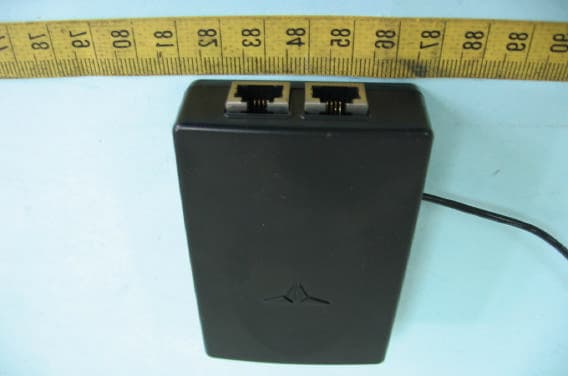
Click to zoom
Application Details
- Equipment Class
- DSC - Part 15 Security/Remote Control Transmitter
- Date of Grant
- Sep 03, 2007
- Application Purpose
- Original Equipment
- Date of Application
- Sep 03, 2007
- Equipment Note
- RADARNODE
- Frequency Range
- 433.80800000 - 433.80800000
- Country
- United Kingdom
Documents & Files
Document Text
Text extracted from the exhibit documents filed with the FCC. Open a document above to read the original.
Users Manual
RADARnode user manual. What it is Thank you for purchasing the RADARnode, the world’s most advanced remote mounting system for radar detectors. The RADARnode is the only remote mounting system that can convey both the alert type and the signal strength of radar threats to your chosen display. It’s an invaluable tool for helping you to use radar detectors more effectively and more discreetly. What’s in the kit 1 x RADARnode 1 x connector cable (specific to your radar detector) 1 x software card (specific to your radar detector) 1 x fused power cord Mounting your Radar detector Consult your dealer for advice on the correct remote mounting locations for radar detectors. Each install is different and you should pick a suitable location, ensuring that the mounting does not interfere with the mechanical operation of your vehicle in any way. Connecting the RADARnode to your radar detector The RADARnode powers your radar detector and relays its detection alerts wirelessly to your chosen display. Please note that the RADARnode is not waterproof so care should be taken to position the unit in a dry area to protect it from the elements. 1. The correct connector cable for your make and model of radar detector must be used. Connect it to your radar detector’s power socket and headphone socket. (The Valentine 1 does not have a headphone socket, so V1 users must ensure the RDI connector cable is installed the correct way round. The ends of the RDI cable for the V1 cable are labelled accordingly.) 2. Safely route the cable from the radar detector to where the RADARnode is located and secure it wherever possible. Ensure the cable will never come into contact with any high temperature engine component or the exhaust system. 3. Plug the connector cable into the socket marked “DETECTOR” on the RADARnode. 4. Insert the software card into the slot on the side of the RADARnode. Always ensure the power is OFF before removing or inserting your software card. 5. If you are also using a Laser Jammer Interface, you should connect the short lead on the RADARnode to the corresponding lead on the LASERnode. When connected together, the RADARnode will be temporarily disabled during the more important jammer alerts. 6. Using the standard RJ11 (telephone style) power cord supplied with the radar detector, plug it into the socket marked “POWER” on the RADARnode. Alternatively, use the supplied fused power cord and plug it into the socket marked “POWER” on the RADARnode. Testing the RADARnode The button on the side of the RADARnode can be pressed and released to check the wireless connection between the RADARnode and the Vizalert display. The display will flash each LED in sequence. What if I change my radar detector. Replacement software cards are unique to each model of radar detector. If you change your radar detector, you must also replace the software card to match your new detector. Software cards will only work with the particular make and model of detector they are designed for. Please check that you have been supplied with the correct software card for your individual detector. New software cards can be purchased from your dealer or online from www.speedcheetah.com. The RADARnode connector cable can sometimes be used on a different model of radar detector. For example, many Beltronics and Escort detectors use the same RADARnode connector cable. However Valentine 1, Escort SR7, Beltronics Vector LR, Beltronics 975 and Target EVO966 RM detectors have unique connector cables that are not transferable. Technical Details RADARnode Power Requirements: Operating voltage: 12V DC RADARnode Dimensions and Weight: 81mm x 54 x 34 mm. 70 gms. Temperature Range: Operating: -10°C to +60°C (14°F to +140°F) Storage: -20°C to +70°C (-4°F to +158°F) Operating Humidity: 5% to 95% (non condensing) Support Troubleshooting If for any reason a Cheetah product develops a fault, please check our support page on www.speedcheetah.com/support. If any problems persist, please email [email protected] Product registration Register online at www.speedcheetah.com/support Accessories Full details of accessory products are available on our website at www.speedcheetah.com Service If any Cheetah product needs repair: Before sending any products back to us for service, please check our support page on www.speedcheetah.com/support or contact us at [email protected]. Do not attempt to service this product yourself. Do not open, puncture or disassemble the product. If the product fails to function, follow these instructions to obtain factory service. Where to ship: Contact us at [email protected] for country specific return address details. How to ship: Ship the unit prepaid and insured, in its original packaging or other strong protective packaging. We cannot be held responsible for any returned product until it has been delivered to our premises. Insist on a proof-of-delivery receipt. Please include the following information with your return: a) your name and return shipping address b) description of the problem c) your daytime telephone number d) proof of purchase if you did not buy the unit directly from us Out of warranty repairs: If your unit is out of warranty (older than one year), we will contact you with an estimated repair cost. If the unit has been damaged, abused or modified, the repair cost will be calculated on a parts and labor basis. Features, specifications and prices subject to change without notice Limited Warranty Cheetah Advanced Technologies Ltd. Warrant our products against all defects in materials and workmanship for a period of one year from the date of the original purchase, subject to the following terms and conditions. This warranty is limited to the original owner, and is Non-Transferable. This warranty does not apply if the serial number has been removed or is unreadable or if the product has been subjected to physical abuse, improper installation, modification or internal examination. To obtain warranty…
Text truncated - open the document above for the full version.
Cover Letter(s)
25 th April, 2007 Compliance Certification Services Certification Division 561F Monterey Road Morgan Hill, CA 95037 To whom it may concern: We, the undersigned, hereby authorize ELECTRONICS TESTING CENTER, TAIWAN, to act on our behalf in all manners relating to application for equipment authorization, including signing of all documents relating to these matters. Any and all acts carried out by ELECTRONICS TESTING CENTER, TAIWAN on our behalf shall have the same effect as acts of our own. We, the undersigned, hereby certify that we are not subject to a denial of federal benefits, that includes FCC benefits, pursuant to Section 5301 of the Anti-Drug Abuse Act of 1988, 21 U.S.C. 853(a). In authorizing ELECTRONICS TESTING CENTER, TAIWAN as our agent, we still recognize that we are responsible to: a) comply with the relevant provisions of the certification program; b) make all necessary arrangements for the conduct of the evaluation, including provision for examining documentation and access to all areas, records (including internal audit reports) and personnel for the purposes of evaluation (e.g. testing, inspection, assessment, surveillance, reassessment) and resolution of complaints; c) make claims regarding certification only in respect of the scope for which certification has been granted; d) do not use our product certification in such a manner as to bring the Certification Division into disrepute and not make any statement regarding our product certification which the Certification Division may consider misleading or unauthorized; e) upon suspension or cancellation of certification, discontinue use of all advertising matter that contains any reference thereto and return any certification documents as required by the Certification Division; f) use certification only to indicate the products are certified as being in conformity with specified standards; g) endeavor to ensure that no certificate or report nor any part thereof is used in a misleading manner; h) ensure that any reference to our product certification in communication media such as documents, brochures or advertising, complies with the requirements of the Certification Division; i) keep a record of all complaints made known to the us relating to the product’s compliance with requirements of the relevant standard and to make these records available to the Certification Division when requested; j) take appropriate action with respect to such complaints and any deficiencies found in products or services that affect compliance with the requirements for certification; k) document the actions taken. This authorization is valid until further written notice from the applicant. Sincerely Yours, Stuart Smith Operations Manager Cheetah Advanced Technologies Ltd
Cover Letter(s)
25 th April, 2007 Federal Communications Commission FCC ID: ULHRADARNODE-01 Product Name: RADARNODE Model Name: RN1 Trade Name: RADARNODE Dear Sir: In accordance with 47 C.F.R. Section 0.459, we would like to request confidentiality on some exhibits we submitted for above application for the reason of trade secret. If those exhibits are available for public inspection, any person who once gets the information contained in those exhibits will be able to design and to make the same products very easily. This is a very serious problem and huge loss for us, because we did invest so much on it. Please do not make the Exhibit Types listed below routinely available for public inspection: Block Diagram and Schematics and Operation Description. By: By: Stuart Smith Title : Mr Applicant : Cheetah Advanced Technologies Ltd Address : Birchbrook House, Doune Road, Dunblane, UK, FK15 9ND Tel : +44 870 243 3824 Fax: +44 870 321 0654 Date : 25/Apr/2007
Cover Letter(s)
1 Chris Harvey From: SS [[email protected]] Sent: Tuesday, September 04, 2007 5:56 AM To: [email protected] Cc: R00/林慧君; Mike Kuo Subject: Re: Cheetah Advanced Technologies Ltd, FCC ID: ULHRADARNODE-01, Assessment NO.: AN07T6970, Notice#1 Attachments: Exhibit-K-O_D_rev.pdf; ULHRADARNODE-01_supporting_details.pdf; Exhibit-C- Test_Report_rev.pdf Exhibit-K-O_D_rev. pdf (52 KB) ULHRADARNODE-0 1_supporting_det... Exhibit-C-Test_Rep ort_rev.pdf ... Dear Chris, 1. This device detects specific external audio signal then activate the RF transmission for controlling a remote display. Please refer to the revised technical description and the supporting details from the applicant. 2. This device is operated automatically. Please refer to the revised technical description and the supporting details from the applicant. Please also refer to the revised test report. 3. The revised technical description was attached. 4. This device was tested in 3 oriented axis following the measurement procedure of section 4.2. Due to the small size of the EUT, a two-side adhesive tape was used to fix it on the table. Best regards, S. S. Liou Engineer / EMC Dept. II Electronics Testing Center, Taiwan ----- Original Message ----- From: <[email protected]> To: <[email protected]> Cc: <[email protected]> Sent: Wednesday, July 04, 2007 9:27 PM Subject: Cheetah Advanced Technologies Ltd, FCC ID: ULHRADARNODE-01, Assessment NO.: AN07T6970, Notice#1 > Dear SS Liou, > > You are listed as the Technical Contact for the above referenced TCB application. The following item(s) need(s) to be resolved before the review can be continued: > > 1. This device apparently is a data transmitter operating under FCC Periodic Operations section 15.231. Data transmission is allowed under 15.231(a), provided that it is sent to supplement a control signal. Please explain how this device meets the requirements of 15.231(a). > > The FCC provided the following guidance/clarification in February 2007: > Data only transmission prohibited under 15.231(a-d). Transmission of 2 temperature, pressure and elapsed time are considered data and are not allowed unless transmitted with a remote control signal. > > 2. The test report indicates that this is operated manually, but the activation seems to be triggered automatically by a Radar Detector event. Is this manual or automatic transmission according to the FCC definitions below? > Manual activation means that you, yourself, personally physically move an actual switch, lever, or whatever, the movement of which causes the transmitter to transmit. > Automatic operation means that a sensor detects a change in something and causes the transmitter to activate as a result of that change without any intervention by some person. > > 3. Please provide a better Technical Description that explains how the transmitter is activated, when it transmits, what control signals or data is transmitted and how the transmission is deactivated. > > 4. Was this device oriented in 3 axis? The test photos do not show any means of reorienting the EUT. > > The items indicated above must be submitted before processing can continue on the above referenced application. Failure to provide the requested information within 30 days of the original e-mail date may result in application dismissal and forfeiture of the filing fee. Also, please note that partial responses increase processing time and should not be submitted. Any questions about the content of this correspondence should be directed to the e-mail address listed below the name of the sender. > > Best regards, > > Chris Harvey > [email protected] >
Cover Letter(s)
ELECTRONICS TESTING CENTER,TAIWAN EMI Laboratory No. 34 , 5 Ln. Ding Fu Tsun Linkou Town Taipei Hsien Taiwan 6 th August 2007 FCC ID: ULHRADARNODE-01 Product Name: RADARNODE Model Name: RN1 Trade Name: RADARNODE Dear Sirs, With reference to the above application, I hereby supply additional information to support the application. The RADARNODE product is designed to work in conjunction with a product called the Escort Passport 8500 X50. Together, the RADARNODE and the Escort Passport 8500 X50 operate as a system. The Escort Passport 8500 X50 product is equipped with an automatic muting facility as standard. This automatic muting facility ceases the audio output of the Escort Passport 8500 X50 within 4 seconds of initial activation. This ensures that the RADARNODE product automatically ceases transmission in under 5 seconds from initial activation. This action is performed automatically by the connected device. Best regards, Stuart Smith
External Photos
ETC Report No.:07-05-RBF-037 FCC ID.: ULHRADARNODE-01 Rev. No 1.0 CONSTRUCTED PHOTOS of EUT Front View of EUT Rear View of EUT ETC Report No.:07-05-RBF-037 FCC ID.: ULHRADARNODE-01 Rev. No 1.0 CONSTRUCTED PHOTOS of EUT Side View of EUT Side View of EUT ETC Report No.:07-05-RBF-037 FCC ID.: ULHRADARNODE-01 Rev. No 1.0 CONSTRUCTED PHOTOS of EUT Top View of EUT Bottom View of EUT
ID Label/Location Info
40 mm 20mm
Internal Photos
ETC Report No.:07-05-RBF-037 FCC ID.: ULHRADARNODE-01 Rev. No 1.0 CONSTRUCTED PHOTOS of EUT Internal View of EUT ETC Report No.:07-05-RBF-037 FCC ID.: ULHRADARNODE-01 Rev. No 1.0 CONSTRUCTED PHOTOS of EUT Component View of Main PCB Solder View of Main PCB
Test Report
Rev. No 1.0 FCC Part 15 EMI TEST REPORT of E.U.T. : RADARNODE FCC ID. : ULHRADARNODE-01 Model : RN1 Working Frequency : 433.925MHz for APPLICANT : Cheetah Advanced Technologies Ltd ADDRESS : Birchbrook House,Doune Road,Dunblane,UK,FK15 9ND Test Performed by ELECTRONICS TESTING CENTER, TAIWAN NO. 34, LIN 5, DING FU TSUN, LINKOU HSIANG TAIPEI HSIEN, TAIWAN, R.O.C. Tel : (02)26023052 Fax : (02)26010910 http://www.etc.org.tw ; e-mail: [email protected] Report Number : 07-05-RBF-037 ETC Report No.:07-05-RBF-037 FCC ID.: ULHRADARNODE-01 Rev. No 1.0 TEST REPORT CERTIFICATION Applicant : Cheetah Advanced Technologies Ltd Birchbrook House,Doune Road,Dunblane,UK,FK15 9ND Manufacture : YOUR LONG ENTERPRISES CO. NO.10, TSAUYAJUNG ST., KAOHSIUNG CITY, TAIWAN, R.O.C. Description of EUT : a) Type of EUT : RADARNODE b) Trade Name : RADARNODE c) Model No. : RN1 d) FCC ID : ULHRADARNODE-01 e) Working Frequency : 433.925 MHz f) Power Supply : DC 12V Regulation Applied : FCC Rules and Regulations Part 15 Subpart C (2006) I HEREBY CERTIFY THAT; The data shown in this report were made in accordance with the procedures given in ANSI C63.4 and the energy emitted by the device was founded to be within the limits applicable. I assume full responsibility for accuracy and completeness of these data. Note : 1. The results of the testing report relate only to the items tested. 2. The testing report shall not be reproduced except in full, without the written approval of ETC. Date Test Item Received : May. 07, 2007 Date Test Campaign Completed : May. 19, 2007 Date of Issue : Jun. 26, 2007 Test Engineer : ( Max Wu ) Approve & Authorized : Will Yauo, Manager EMC Dept. II of ELECTRONICS TESTING CENTER, TAIWAN ETC Report No.:07-05-RBF-037 FCC ID.: ULHRADARNODE-01 Rev. No 1.0 Table of Contents Page 1. GENERAL INFORMATION ............................................................................................................................... 1 1.1 PRODUCT DESCRIPTION.......................................................................................................................................... 1 1.2 CHARACTERISTICS OF DEVICE: ...............................................................................................................................1 1.3 TEST METHODOLOGY............................................................................................................................................. 1 1.4 TEST FACILITY........................................................................................................................................................ 1 2. DEFINITION AND LIMITS................................................................................................................................. 2 2.1 DEFINITION............................................................................................................................................................. 2 2.2 RESTRICTED BANDS OF OPERATION........................................................................................................................ 2 2.3 LIMITATION............................................................................................................................................................. 2 2.4 LABELING REQUIREMENT....................................................................................................................................... 4 2.5 USER INFORMATION................................................................................................................................................ 4 3 SYSTEM TEST CONFIGURATION.................................................................................................................... 5 3.1 JUSTIFICATION........................................................................................................................................................ 5 3.2 DEVICES FOR TESTED SYSTEM................................................................................................................................5 4. RADIATED EMISSION MEASUREMENT....................................................................................................... 6 4.1 APPLICABLE STANDARD.......................................................................................................................................... 6 4.2 MEASUREMENT PROCEDURE.................................................................................................................................. 6 4.3 TEST DATA............................................................................................................................................................. 8 4.4 FIELD STRENGTH CALCULATION........................................................................................................................... 10 4.5 ACTIVATE TIME.................................................................................................................................................... 10 4.6 CALCULATION OF DUTY FACTOR.......................................................................................................................... 10 4.7 RADIATED TEST EQUIPMENT................................................................................................................................15 4.8 MEASURING INSTRUMENT SETUP.......................................................................................................................... 15 4.9 RADIATED MEASUREMENT PHOTOS...................................................................................................................... 16 5. BANDWIDTH OF EMISSION........................................................................................................................... 17 5.1 APPLICABLE STANDARD PLOT GRAPHIC OF BANDWIDTH...................................................................................... 17 5.2 BANDWIDTH TEST EQUIPMENT...............................…
Text truncated - open the document above for the full version.
Test Setup Photos
ETC Report No.:07-05-RBF-037 FCC ID.: ULHRADARNODE-01 Rev. No 1.0 4.9 Radiated Measurement Photos
Contact Information
Applicant
Stuart Smith(Operations Manager)
Test Firm
Electronics Testing Center, TaiwanWill Yauo
Technical Specifications
| # | Rule Parts | Frequency Range | Power Output |
|---|---|---|---|
| 1 | 15.231 | 433.808 MHz - 433.808 MHz | - |