ULS-M0198Wireless mini-PCI Card
NU Inc.
Click to zoom
Application Details
- Equipment Class
- DTS - Digital Transmission System
- Date of Grant
- Mar 29, 2007
- Application Purpose
- Original Equipment
- Date of Application
- Mar 29, 2007
- Equipment Note
- Wireless mini-PCI Card
- Frequency Range
- 2412.00000000 - 2462.00000000
- Company
- NU Inc.
- Country
- Taiwan
Documents & Files
Document Text
Text extracted from the exhibit documents filed with the FCC. Open a document above to read the original.
Users Manual
chapter 1 getting to know the basics CHAPTER ONE GETTING TO KNOW THE BASICS This chapter introduces the features and components of the computer. 1-1 chapter 1 getting to know the basics Performance Features High Performance Processor The notebook PC is equipped with a powerful Intel processor of the latest sub-micron process, processor technologies, and high bus bandwidths. Advanced Graphic Engine An on-board nVidia GeForce FX Go5600 video processor with dedicated 64MB or 128MB frame buffer gives excellent graphic performance. The advanced graphic chip also incorporates a hardware-based motion-compensation engine, which gives you smooth MPEG video playback. 3D graphics capability also adds realism to PC games. Alternatively, ATI Mobility Radeo 9?00 video processor with dedicated 64MB or 128MB frame buffer may be built into the system. Large LCD Display The computer is equipped with a large 16-inch or 15.4-inch (wide aspect ratio) TFT high-resolution display panel for clear text and brilliant colors. Expandability The system offers upgradeable hard disk drive and 2 DDR SDRAM sockets for expansion, allowing the user to easily increase the storage and system capacities as the need arises. Swappable Device Bay The swappable device bay allows user to add an additional hard disk drive module for increased storage capacity. 1-2 chapter 1 getting to know the basics Built-in Multifunction Card Reader (Optional) Some system may come with a multiple card reader, which supports SD, MS, MMC Card formats. This allows user to access a wide array of portable memory devices available today. Communication Features The system provides built-in Ethernet network adapter for local network and 56K modem. Firewire (IEEE1394 / 1394a) and USB2.0 ports In addition to a full array of built-in I/O por ts, the computer offers IEEE1394 for ultra high-speed connection to high bandwidth digital video devices and USB2.0 ports to connect to any USB-based peripheral devices. Wireless LAN (Optional) or Bluetooth (Optional) The optional internal Wireless LAN module allows your notebook to connect wirelessly to other 802.11-enabled systems, devices, or network. Alternatively, the system may come with an optional Bluetooth module. TV Tuner (Optional) The optional TV Tuner module allows user to watch TV or cable programs, record TV, and capture analog video signals to the hard drive or to the recordable optical drive (optional device). 1-3 chapter 1 getting to know the basics 1-11 chapter 1 getting to know the basics Bottom View 1. Ventilation Grill The fan grill is where air is exchanged to dissipate the internal heat. Do not block this airway completely. 2. Swappable Device Bay and Latch Push the latch and pull on the drive hard case to remove the swappable device. Note: The optical drive resides in the Swappable Device Bay. Additionally, you may also purchase an optional hard drive module to be used in this bay. 1-12 chapter 1 getting to know the basics 3. Hard Disk Drive This is the system’s hard drive module. The hard disk drive stores all the system data. The hard disk drive can be upgraded to a larger capacity. (See Chapter 4 for instructions on a hard drive upgrade.) 4. Battery Pack and Battery Latch The battery pack is a built-in power source for the notebook. Slide the battery latch to release the battery pack. 1-13 chapter 1 getting to know the basics AC Adapter 1. DC-out Connector The DC-out connector docks to the power jack (DC-in) on the computer. 2. LED Lamp The LED lamp appears green when the unit is plugged into a valid AC source. 3. Adapter The adapter converts alternating current into constant DC voltage for the computer. 4. AC Plug The AC plug plugs to the AC wall outlet. Warning: Make sure you are using a standard 3-prong AC wall socket with a ground pin. If not, you may feel a slight tingling sensation on any of the computer’s metal parts such as the I/O ports. This is caused by leakage current when the AC adapter is not properly grounded (via the ground pin). However, the amount of leakage current is within the safety regulation and is not harmful to human body. 1-14 chapter 1 getting to know the basics TV Tuner / Video Capturing Module and Video / Audio Input Breakout Cable (Optional Device) Your system may a video-capturing module built-in. To record or watch TV programs, connect the external TV Tuner Module to the TV Tuner port on the notebook. If the device driver and application have not been installed to your system, you may need to do so via the factory CD-ROM disc when you first power up the notebook. S-Video in Video in Audio Left in Audio Right in Cable in / Antenna To Notebook External TV Tuner Module Alternatively, you may also use the Video / Audio Input Breakout Cable to connect to external video sources, such as a camcorder, DVD, or VCR. S-Video in Video in (Yellow) Audio Left in (White) Audio Right in (Red) To Notebook 1-15 chapter 1 getting to know the basics Remote Control (Optional Device) If your system comes with a TV Tuner / Video Capturing module, the remote control can be used to play or record TV programs. You may need to install the device driver and recording application before the remote control can be used. See the following illustration for a general description of the keys. See section elsewhere in this chapter for TV playback or record functions or see the device’s CD-ROM or help screen in the application for detailed instructions. Note: Your system may come with a different remote control. Please consult the user manual in the factory CD-ROM disc. 1-16 chapter 1 getting to know the basics How to Use the Romote, Watch TV and Record Video Clips The following is a brief guide. You need to install the card’s driver and recording application from PixelView’s installation CD-ROM disk. You need to install a utility program called TV Card or PixelView in order to use the card’s function. Connect a video source, cable, or antenna to the TV Tuner Module. …
Text truncated - open the document above for the full version.
ID Label/Location Info
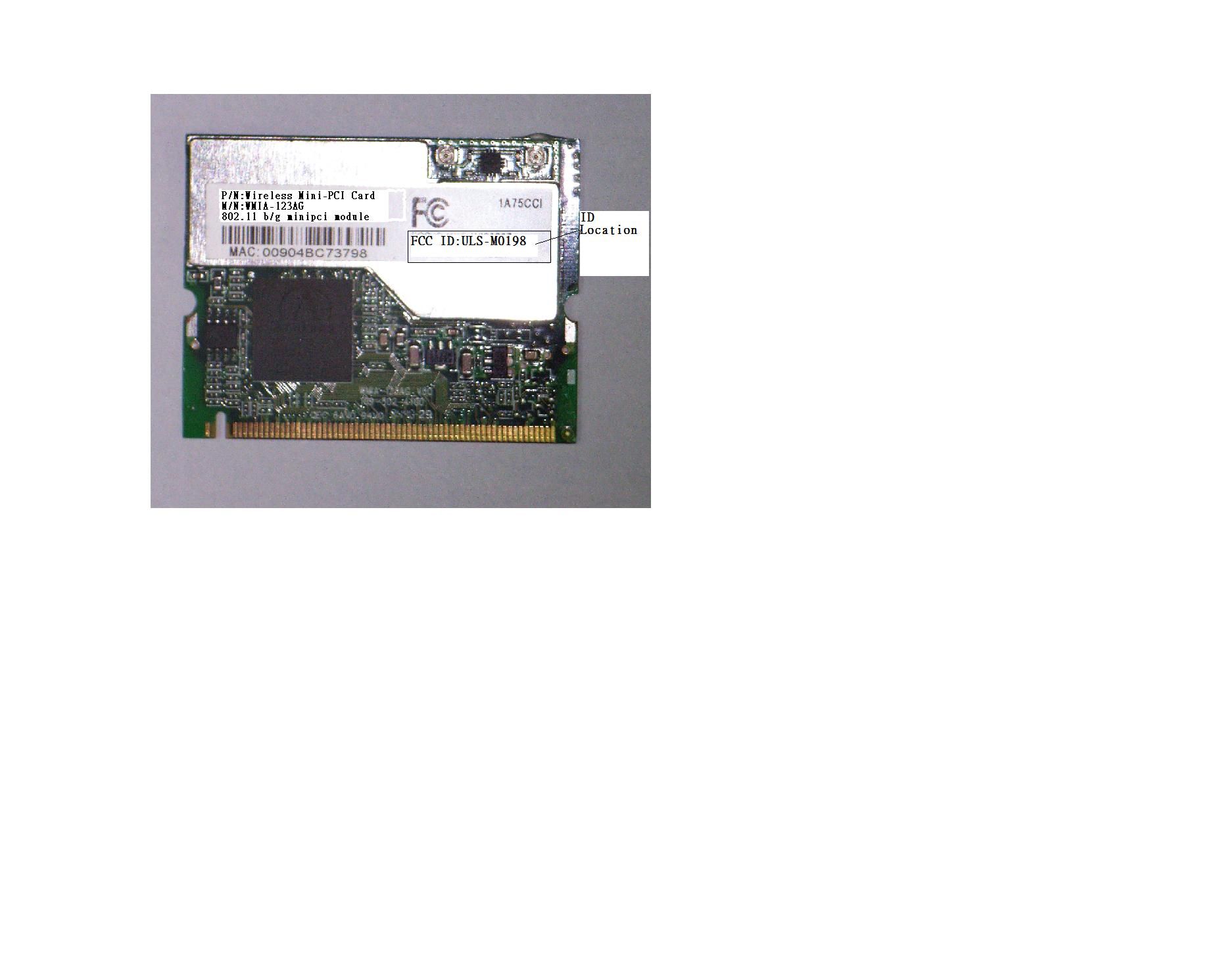
FCCID:ULSM0198
Operational Description
OperationalDescription FederalCommunicationCommissionInterferenceStatement ThisequipmenthasbeentestedandfoundtocomplywiththelimitsforaClass B digitaldevice,pursuanttoPart15oftheFCCRules.Theselimitsaredesigned to providereasonableprotectionagainstharmfulinterferenceinaresidential installation.Thisequipmentgenerates,usesandcanradiateradiofrequency energyand,ifnotinstalledandusedinaccordancewiththeinstructions,may causeharmfulinterferencetoradiocommunications.However,thereisno guaranteethatinterferencewillnotoccurinaparticularinstallation.Ifthis equipmentdoescauseharmfulinterferencetoradioortelevisionreception, which canbedeterminedbyturningtheequipmentoffandon,theuseris encouragedto trytocorrecttheinterferencebyoneofthefollowingmeasures: Reorientorrelocatethereceivingantenna. Increasetheseparationbetweentheequipmentandreceiver. Connecttheequipmentintoanoutletonacircuitdifferentfromthattowhich the receiverisconnected. Consultthedealeroranexperiencedradio/TVtechnicianforhelp. FCCCaution:Toassurecontinuedcompliance,anychangesormodifications not expresslyapprovedbythepartyresponsibleforcompliancecouldvoidthe user's authoritytooperatethisequipment. ThisdevicecomplieswithPart15oftheFCCRules.Operationissubjecttothe followingtwoconditions:(1)Thisdevicemaynotcauseharmfulinterference, and (2)thisdevicemustacceptanyinterferencereceived,includinginterference that maycauseundesiredoperation. StatementNeededtobeShownonEndProduct Sincethismoduleisinstalledinsidetheendproduct,theendproductshould beaffixedalabelonvisibleareashowingthatthisproductcontainaRF module,andalsoitsFCCID. IMPORTANTNOTE: FCCRadiationExposureStatement: ThisequipmentcomplieswithFCCradiationexposurelimitssetforthforan uncontrolledenvironment.Thisequipmentshouldbeinstalledandoperated withminimumdistance20cmbetweentheradiator&yourbody. Thistransmittermustnotbecolocatedoroperatinginconjunctionwithany otherantennaortransmitter. TheOEMintegratorhastobeawarenottoprovideinformationtotheenduser regardinghowtoinstallorremovethisRFmoduleintheusersmanualofthe endproductwhichintegratethismodule. ThisdeviceisintendedonlyforOEMintegratorsunderthefollowing conditions: 1)Theantennamustbeinstalledsuchthat20cmismaintainedbetweenthe antennaandusers,and 2)Thetransmittermodulemaynotbecolocatedwithanyothertransmitteror antenna. Aslongasthe2conditionsabovearemet,furthertransmittertestingwillnot berequired.However,theOEMintegratorisstillresponsiblefortestingtheir endproductforanyadditionalcompliancerequirementsrequiredwiththis moduleinstalled(forexample,NB,AP,Router) IMPORTANTNOTE:Intheeventthattheseconditionscannotbemet(for examplecertainlaptopconfigurationsorcolocationwithanothertransmitter), thentheFCCauthorizationisnolongerconsideredvalidandtheFCCIDcan notbeusedonthefinalproduct.Inthesecircumstances,theOEMintegrator willberesponsibleforreevaluatingtheendproduct(includingthetransmitter) andObtainingaseparateFCCauthorization. EndProductLabelling Thistransmittermoduleisauthorizedonlyforuseindeviceswherethe antennamaybeinstalledsuchthat20cmmaybemaintainedbetweenthe antennaandusers(forexample:NB,AP,Router) ManualInformationThatMustbeIncluded Theusersmanualforendusersmustincludethefollowinginformationina prominentlocation“ IMPORTANTNOTE:TocomplywithFCCRFexposurecompliance requirements, theantennausedforthistransmittermustbeinstalledtoprovideaseparation distanceofatleast20cmfromallpersonsandmustnotbecolocatedor operatinginconjunctionwithanyotherantennaortransmitter.”
Operational Description
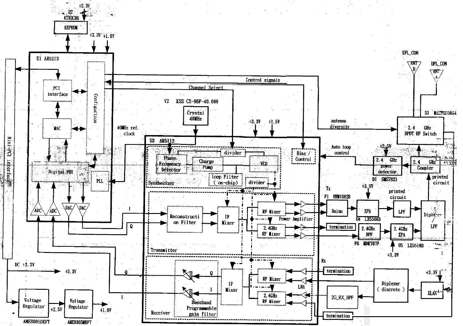
FCCID:ULSM0198 TechnicalDescription ThetransmitteroftheEUT(WirelessB+GMiniPCICard)ispowered byhostequipmentviaaPCMCIAinterface.Theantennatypesusedin thisproductarePrintedandDipolewithUFLantennaconnector.Under normalusecondition,theuserhastokeepatleast20cmseparation distanceandthebodyoftheuser. ThisdeviceisawirelessB+GMiniPCICard,whichoperatesinbothof the2.4GHzbandsandcantransmittingsimultaneously,themaximum dataratecouldbe54Mbps. Formoredetailedinstruction,pleasetakealookattheuser’smanual. FCC15.407(c)states:Thedeviceshallautomaticallydiscontinue transmissionincaseofeitherabsenceofinformationtotransmitor operationfailure.Theseprovisionsarenotintendedtoprecludethe transmissionofcontrolorsignalinginformationortheuseof repetitivecodesusedbycertaindigitaltechnologiestocomplete frameorburstintervals. Applicantsshallincludeintheirapplicationforequipment authorizationadescriptionofhoethisrequirementinmet” Datatransmissionisalwaysinitiatedbysoftware,whichisthenpass downthroughtheMAC,throughthedigitalandanalogbaseband,and finallytotheRFchip.Severalspecialpackets(ACKs,CTS,PSPoLll, etc...)areinitiatedbytheMAC.Therearetheonlywaysthedigital basebandportionwillturnontheRFtransmitter,whichitthenturns offattheendofthepacket.Therefore,thetransmitterwillbeononly whileoneoftheaforementionedpacketsarebeingtansmitted.
Test Report
Compliance Certification Services Inc. Report No.: 60613212-RP1 FCC ID: ULS-M0198 Date of Issue: December 14, 2006 Note: This report shall not be reproduced except in full, without the written approval of Compliance Certification Services Inc. This document may be altered or revised by Compliance Certification Services Inc. personnel only, and shall be noted in the revision section of the document. Page 1 Total Page: 61 Rev. 00 FCC 47 CFR PART 15 SUBPART C TEST REPORT For Wireless mini-PCI Card Model: WMIA-123AG 802.11 b+g Mini PCI Module Trade Name: NU Issued to NU Inc. 2F-6/No 5, Alley 22, Lane 513, Rue Guang Rd, Taipei 114, Taiwan, R.O.C. Issued by Compliance Certification Services Inc. No. 81-1, Lane 210, Bade Rd. 2, Luchu Hsiang, Taoyuan Hsien, (338) Taiwan, R.O.C. http://www.ccsemc.com.tw [email protected] Compliance Certification Services Inc. Report No.: 60613212-RP1 FCC ID: ULS-M0198 Date of Issue: December 14, 2006 Page 2 Rev. 00 TABLE OF CONTENTS 1. TEST RESULT CERTIFICATION........................................................................................................3 2. EUT DESCRIPTION..............................................................................................................................4 3. TEST METHODOLOGY.......................................................................................................................5 3.1 EUT CONFIGURATION........................................................................................................................5 3.2 EUT EXERCISE....................................................................................................................................5 3.3 GENERAL TEST PROCEDURES.............................................................................................................5 3.4 FCC PART 15.205 RESTRICTED BANDS OF OPERATIONS........................................................6 3.5 DESCRIPTION OF TEST MODES...........................................................................................................7 4. INSTRUMENT CALIBRATION...........................................................................................................8 4.1 MEASURING INSTRUMENT CALIBRATION......................................................................................8 4.2 MEASUREMENT EQUIPMENT USED.........................................................................................8 5. FACILITIES AND ACCREDITATIONS ..............................................................................................9 5.1 FACILITIES .........................................................................................................................................9 5.2 EQUIPMENT........................................................................................................................................9 5.3 TABLE OF ACCREDITATIONS AND LISTINGS.....................................................................................10 6. SETUP OF EQUIPMENT UNDER TEST...........................................................................................11 6.1 SETUP CONFIGURATION OF EUT.......................................................................................................11 6.2 SUPPORT EQUIPMENT ...............................................................................................................11 7. FCC PART 15.247 REQUIREMENTS................................................................................................12 7.1 6 DB BANDWIDTH.............................................................................................................................12 7.2 PEAK POWER....................................................................................................................................17 7.3 A VERAGE POWER............................................................................................................................22 7.4 BAND EDGES MEASUREMENT ................................................................................................26 7.5 PEAK POWER SPECTRAL DENSITY....................................................................................................35 7.6 SPURIOUS EMISSIONS ................................................................................................................40 7.7 POWERLINE CONDUCTED EMISSIONS...............................................................................................54 APPENDIX I RADIO FREQUENCY EXPOSURE ...................................................................................57 APPENDIX II PHOTOGRAPHS OF TEST SETUP ..................................................................................59 Compliance Certification Services Inc. Report No.: 60613212-RP1 FCC ID: ULS-M0198 Date of Issue: December 14, 2006 Page 4 Rev. 00 2. EUT DESCRIPTION Product Wireless mini-PCI Card Trade Name NU Model Number WMIA-123AG 802.11 b+g Mini PCI Module Model Discrepancy N/A Power Supply Powered from host device Frequency Range 2.412~2.462 GHz Transmit Power IEEE 802.11b: 21.20 dBm IEEE 802.11g: 18.01 dBm Modulation Technique IEEE 802.11b: DSSS (CCK, DQPSK, DBPSK) IEEE 802.11g: DSSS (CCK, DQPSK, DBPSK) + OFDM (QPSK, BPSK, 16-QAM, 64-QAM) Transmit Data Rate IEEE 802.11b: 11, 5.5, 2, 1 Mbps IEEE 802.11g: 54, 48, 36, 24, 18, 12, 11, 9, 6, 5.5, 2, 1Mbps Number of Channels 11 Channels Antenna Specification dual-band (PIFA) Antenna / Gain: 2.5dBi Remark: 1. The sample selected for test was engineering sample that approximated to production product and was provided by manufacturer. 2. This submittal(s) (test report) is intended for FCC ID: ULS-M0198 filing to comply with Section 15.207, 15.209 and 15.247 of the FCC Part 15, Subpart C Rules. Compliance Certification Services Inc. Report No.: 60613212-RP1 FCC ID: ULS-M0198 Date of Issue: December 14, 2006 Page 5 Rev. 00 3. TEST METHODOLOGY The tests documented in this report were performed in…
Text truncated - open the document above for the full version.
Test Setup Photos
Compliance Certification Services Inc. Report No.: 60613212-RP1 FCC ID: ULS-M0198 Date of Issue: December 14, 2006 Page 59 Rev. 00 APPENDIX II PHOTOGRAPHS OF TEST SETUP Conducted Emission Setup Photos Compliance Certification Services Inc. Report No.: 60613212-RP1 FCC ID: ULS-M0198 Date of Issue: December 14, 2006 Page 60 Rev. 00 Radiated Emission Setup Photos Compliance Certification Services Inc. Report No.: 60613212-RP1 FCC ID: ULS-M0198 Date of Issue: December 14, 2006 Page 61 Rev. 00 Powerline Conducted Emissions Setup Photos
Contact Information
Applicant
LEO STONE
Test Firm
Compliance Certification Services Inc.Kurt Chen
Technical Specifications
| # | Rule Parts | Frequency Range | Power Output |
|---|---|---|---|
| 1 | 15C | 2.41 GHz - 2.46 GHz | 130.00 mW |
Other Applications from NU Inc.

ULS-DVC
Feb 12, 2012DivEr Camcorder
Equipment Class
JBP - Part 15 Class B Computing Device Peripheral